
MICROWAVE HOOD COMBINATION
INSTALLATION INSTRUCTIONS
This product is suitable for use above electric or gas cooking products up to and including 30" (76.2 cm) wide. See
"Installation Requirements" section for further notes.
These installation instructions cover different models. The appearance of your particular model may differ slightly from the
illustration in these installation instructions.
INSTRUCTIONS D'INSTALLATION
DE L'ENSEMBLE FOUR A MICRO-ONDES/HOTTE
Ce produit est con_u pour rutilisation au-dessus d'appareils de cuisson 61ectriques ou _.gaz de 30" (76,2 cm) de largeur
ou moins. Voir la section "Exigences d'installation" pour d'autres remarques.
Ces instructions d'installation sont valables pour plusieurs modules. IIse peut que I'apparence de votre propre module soit
16g&rement diff6rente de celle montr6e sur les illustrations dans ce document.
Table of Contents / Table des mati_res
MICROWAVE HOOD COMBINATION SAFETY ....................... 1
INSTALLATION REQUIREMENTS ............................................ 2
Tools and Parts ....................................................................... 2
Location Requirements ........................................................... 2
Product Dimensions ................................................................ 3
Electrical Requirements .......................................................... 3
INSTALLATION INSTRUCTIONS .............................................. 4
Remove Mounting Plate .......................................................... 4
Convert Microwave Oven to External Venting ........................ 4
Locate Wall Stud(s) ................................................................. 6
Mark Rear Wall ........................................................................ 7
Drill Holes in Rear Wall ............................................................ 7
Attach Mounting Plate to Wall ................................................ 8
Prepare Upper Cabinet ........................................................... 8
Install the Microwave Oven ..................................................... 9
Complete Installation ........................................................... 10
VENTING DESIGN SPECIFICATIONS ................................... 11
ASSISTANCE ........................................................................... 12
Replacement Parts ............................................................... 12
SleCURITle DE L'ENSEMBLE FOUR .&MICRO-ONDES/HOTTE...13
EXIGENCES D'INSTALLATION ......................................................... 13
Outillage et pieces ........................................................................... 13
Exigences d'emplacement .............................................................. 14
Dimensions du produit .................................................................... 14
Specifications _lectriques ............................................................... 15
INSTRUCTIONS D'INSTALLATION .................................................. 15
D_pose de la plaque de montage ................................................... 15
Four µ-ondes - conversion pour d_charge &I'ext_rieur ....... 15
Identifier la position du/des poteaux du colombage mural ............ 17
Trac_ sur le mur arri_re ................................................................... 18
Pergage de trous dans lemur arriere .............................................. 19
Fixation de la plaque de montage sur lemur ................................. 19
Preparation du placard mural .......................................................... 20
Installation du four & micro-ondes .................................................. 21
Achever I' installation ........................................................................ 22
SPleCIFICATIONS/CONCEPTION DU CIRCUIT D'I_'VACUATION........23
ASSISTANCE ...................................................................................... 24
Pieces de rechange ......................................................................... 24
MICROWAVE HOOD COMBINATION SAFETY
Your safety and the safety of others are very important.
We have provided many important safety messages in this manual and on your appliance. Always read and obey all safety
messages.
This is the safety alert symbol.
This symbol alerts you to potential hazards that can kill or hurt you and others.
All safety messages will follow the safety alert symbol and either the word "DANGER" or "WARNING."
These words mean:
You can be killed or seriously injured if you don't immediately
follow instructions.
You can be killed or seriously injured if you don't follow
instructions.
All safety messages will tell you what the potential hazard is, tell you how to reduce the chance of injury, and tell you what can
happen if the instructions are not followed.
8206646

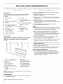
INSTALLATION REQUIREMENTS
The microwave oven is set for recirculation installation. For external (wall or roof) venting, see "Venting Design Specifications" section.
Tools Needed
Gather the required tools and parts before starting installation.
Read and follow the instructions provided with any tools
listed here.
• Measuring tape • Stud finder
• Pencil • 7/16" socket wrench
(or box wrench) for 1/4" x 2"
• Masking tape or thumbtacks lag screws
• Scissors
• 11/2"(3.8 cm) diam. hole drill
• T10 TORX _screwdriver bit for wood or metal
cabinet
• No. 3 Phillips screwdriver for
1/4-20 x 3" bolts • Keyhole saw
• Electric drill • Caulking gun and
weatherproof caulking
• 3/16" (5 mm) and 3/8" compound
(10 mm) drill bits
• Duct tape
• 3/4" (19 mm) hole saw
• Diagonal cutting pliers
Parts Supplied
For information on reordering, see "Replacement Parts" section.
NOTE: The hardware items listed here are for wood studs. For
other types of wall structures, be sure to use appropriate
fasteners.
B E
4 .... • _i ....... _ _ __ _._ _......... _ _.
Check the opening where the microwave oven will be installed.
The location must provide:
• Minimum installation dimensions. See"lnstallation
Dimensions" illustration.
• Minimum one 2" x 4" (50.8 x 101.6 mm) wood wall stud and
minimum 3/8" (10 mm) thickness drywall or plaster/lath within
cabinet opening.
• Support for weight of 150 Ibs (68 kg), which includes
microwave oven and items placed inside the microwave oven
and upper cabinet.
• Grounded electrical outlet inside upper cabinet. See
"Electrical Requirements" section.
NOTES:
• If installing the microwave oven near a left sidewall, make sure
there is at least 3" (7.6 cm) of clearance between the wall and
the microwave oven, so that the door can open fully.
• Some cabinet and building materials are not designed to
withstand the heat produced by the microwave oven for
cooking. Check with your builder or cabinet supplier to make
sure that the materials used will not discolor, delaminate or
sustain other damages.
• For gas cooktop, we recommend that combined cooking
surface rating does not exceed 50,000 BTU/hr.
• The microwave oven is set for recirculation mode. For external
(wall or roof) venting, see "Venting Design Specifications"
section.
Special Requirements
For Wall Venting Installation Only:
• Cutout must be free of any obstructions so that the vent fits
properly, and the damper blade opens freely and fully.
For Roof Venting Installation Only:
• If you are using a rectangular to round transition piece,
3" (7.6 cm) clearance needs to exist above the microwave
oven so that the damper blade can open freely and fully. See
"Rectangular to Round Transition" illustration in "Venting
Design Specifications" section.
A. 1/4-20 x 3" round-head bolts (2)
B. 1/4-20x3" flat-head bolts (2)
C. Washers (2)
D. Toggle nuts (2)
E. 1/4" x 2" lag screws (2)
F. Mounting screws (3)
G. Power supply cord bushing (!)
H. Damper assembly (for wall or roof
venting)
L Vent deflector (for wall or roof
venting)
Not Shown:
Upper cabinet template
Mounting plate (attached to
back of microwave oven)
Aluminum grease filters
Charcoal filters (Depending
on model, charcoal filters
may not be included. See
Use and Care Guide.)
NOTE: Depending on model, aluminum grease filter and charcoal
filter may be combined.
Materials needed
• Standard fittings for wall or roof venting. See "Venting Design
Specifications" section.
1-®TORX is a registered trademark of Textron Innovations Inc.

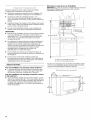
Installation Dimensions
NOTE: The grounded 3 prong outlet must be inside the upper
cabinet. See "Electrical Requirements" section.
A B
69" (175.3 cm) min.
(83.2 cm)
3ica_*
12" (30.5 cm) min.
13" (33.0 cm) max.
Lj..........
ii
A. 2" x 4" wall stud
B. Grounded 3 prong outlet
*33" (83.2 cm)is typical for 69" (175.3 cm) installation height.
Exact dimension may vary depending on type of range/cooktop
below.
T
151/2''
39.4 cm)
Electrical Shock Hazard
Plug into a grounded 3 prong outlet.
Do not remove ground prong.
Do not use an adapter.
Do not use an extension cord,
Failure to follow these instructions can result in death,
fire, or electrical shock.
Observe all governing codes and ordinances.
Required:
[] A 120 Volt, 60 Hz, AC only, 15- or 20-amp electrical supply
with a fuse or circuit breaker.
Recommended:
[] A time-delay fuse or time-delay circuit breaker.
[] A separate circuit serving only this microwave oven.
GROUNDING iNSTRUCTiONS
[] For all cord connected appliances:
The microwave oven must be grounded. In the event of
an electrical short circuit, grounding reduces the risk of
electric shock by providing an escape wire for the electric
current. The microwave oven is equipped with a cord
having a grounding wire with a grounding plug. The plug
must be plugged into an outlet that is properly installed
and grounded.
WARNING: Improper use of the grounding plug can
result in a risk of electric shock. Consult a qualified
electrician or serviceman if the grounding instructions are
not completely understood, or if doubt exists as to whether
the microwave oven is properly grounded.
Do not use an extension cord. If the power supply cord is
too short, have a qualified electrician or serviceman install
an outlet near the microwave oven.
SAVE THESE iNSTRUCTiONS

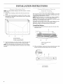
INSTALLATION INSTRUCTIONS
NOTE: To avoidpossibledamage tothework surface,coverthe
work surface.
1. Remove any remaining contents from the microwave oven
cavity.
2. Remove the mounting plate by peeling off the strips of tape
that attach it to the back of the microwave oven, and set the
mounting plate aside.
o o o o o '_
<ii o o o o o o !i o o o o
_ o o o o o ,i o o o o o o o _ o o o o
A B C
i-
A. Mounting plate
B. Back of microwave oven
C. Tape (multiple locations)
3. Tape the microwave oven door closed so that door does not
swing open while the microwave oven is being handled.
NOTE: To avoid damage to the microwave oven, do not grip or
use the door or door handle while the microwave oven is being
handled.
,. (( _." ;;>
The microwave oven is set for recirculation installation. For wall or
roof venting, changes must be made to the venting system. See
"Venting Design Specifications" section.
NOTE: Skip this section if you are using recirculation installation.
Keep the damper assembly in case the venting method is
changed, or the microwave oven is reinstalled in another location
where wall or roof venting may be used.
To prepare the microwave oven for wall or roof venting, the vent
deflector (L-shaped metal bar) must be installed, and the
appropriate damper vent opening must be uncovered.
To Install Vent Deflector:
1. Gently pull the rings and lift vent screen from the top of the
microwave oven.
A
2=
B C
A. Top of microwave oven
B. Vent screen
C. Rings
With vent deflector oriented as shown (wide side down), slide
it back and under the back edge of the vent opening.
......................_ _1777_
A. Vent opening
B.Ventdeflector

3.
When the vent deflector is as far back as it can easily slide, flip
it so that the wide side is to the back of the microwave oven,
and the narrow side (with holes) is down. The vent deflector
holes should align with mounting holes in the vent opening, as
shown in inset.
3. Save the cover for possible change of venting method in the
future.
4. Position the damper assembly so that the long tab slides into
the slot on the right side of the damper vent opening, as
shown. Then secure with mounting screw.
A B
l
A B
J
/
f
/
A. Vent opening
B. Vent deflector
4.
Secure vent deflector with 2 mounting screws (1 on each end).
A B
?
/
A. Mounting screw
B.Ventdeflector
5. Replace vent screen.
Wall Venting Installation Only
To Remove Wall Damper Vent Cover:
1. Locate the wall damper vent cover on the back of the
microwave oven.
2. Using diagonal wire cutting pliers, gently snip out the damper
vent cover at the perforations.
A B C D
A. Mounting screw
B.Damperassembly
C. Long tab (insideslot)
Roof Venting Installation Only
To Remove Roof Damper Vent Cover:
1. Locate the roof damper vent cover on the top of the
microwave oven.
2. Using diagonal wire cutting pliers, gently snip out the damper
vent cover at the perforations.
A B C
D
A. Diagonal wire cutting pliers
B. Top of microwave oven
C. Roof damper vent cover
D. Perforations
3. Save the cover for possible change of venting method in the
future.
NOTE: Do not install damper assembly at this time.
A. Diagonal wire cutting pliers
B. Back of microwave oven
C. Waft damper vent cover
D. Perforations

Ieca eWal5 d(s)
NOTE: If no wall studs exist within the cabinet opening, do not 1. Using a stud finder, locate the edges of the wall stud(s) within
install the microwave oven. the opening.
See illustrations in "Possible Wall Stud Configuralons." 2. Mark the center of each stud, and draw a plumb line down
each stud center. See illustrations in "Possible Wall Stud
Configurations."
Possible Wall Stud Configurations
These depictions show examples of preferred installation configurations with the mounting plate•
No Wall Studs at Corner Holes
Figure 1
No Wall Studs at Corner Holes
Figure2
C
D
NOTE: If wall stud is within 6" (15.2 cm) of the vertical
centerline (see "Mark Rear Wall" section), only recirculation or
roof venting installation can be done.
Wall Stud at One Corner Hole
Figure3
i
i
A. Corner holes (on mounting plate)
B. Cabinet opening vertical centerllne
C. Wall stud centerllnes
D. Holes for lag screws
E. Support tabs
F. Mounting plate center markers
Wall Studs at Both Corner Holes
Figure4
i I
i
i 17_i
i
i d£
I
°i
/C;i
° oooooo°o o o o ° °° ...........A,D
I
it.!..........
i
/i/

The microwave oven must be installed on a minimum of 1 wall
stud, preferably 2, using a minimum of I lag screw, preferably 2.
1. Using measuring tape, find and clearly mark the vertical
centerline of the opening.
A _
A. Centerline
2. With the support tabs facing forward (see illustrations in
"Possible Wall Stud Configurations" in "Locate Wall Stud(s)"
section), align the mounting plate center markers to the
centerline on the wall, making sure it is level, and that the top
of the mounting plate is butted up against the bottom edge of
the upper cabinet.
NOTE: If the front edge of the upper cabinet is lower than the
back edge, lower the mounting plate so that its top is level with
the front edge of the cabinet.
A ...........
C
B
A. Rear wall
B. Mounting plate
C. Top of mounting plate must align
with front edge of cabineL
D. Front edge of upper cabinet
3. Holding the mounting plate in place, mark both bottom corner
holes.
4. Find the wall stud centerline(s) marked in Step 2 of "Locate
Wall Stud(s)," and mark at least 1, preferably 2, hole(s) through
the mounting plate, closest to the centerline(s). See figures 1,
2 and/or 3 in "Possible Wall Stud Configurations" in "Locate
Wall Stud(s)" section. The blackened holes in the shaded
areas are ideal hole locations.
5. Set mounting plate aside.
Wall Venting Installation Only
Centerline
Upper cabinet bottom
f
t
4" (10.2 cm)
6" (15.2 cm) 6" (15.2 cm)
6. Mark the centerline 3/8" (1 cm) down from the bottom edge of
the upper cabinet.
7. Using measuring tape, measure out 6" (15.2 cm) on both sides
of the centedine, and mark.
8. Measure down 4" (10.2 cm) from the mark made in Step 6,
and mark.
9. Using a straightedge, draw the 2 horizontal, level lines through
the marks made in steps 6 and 8.
10. Draw the 2 vertical, plumb lines down from the marks made in
Step 7 to complete the 12" x 4" (30.5 x 10.2 cm) rectangle.
This is the venting cutout area.
11. Cut a 3/4" (19 mm) hole in one corner of the cutout area.
12. Using a keyhole saw, cut out the venting cutout area.
In addition to being installed on at least 1 wall stud, the mounting
plate must attach to the wall at both bottom corner holes. If the
holes are not over wall studs, use two 1/4-20 x 3" round-head
bolts with toggle nuts; if 1 hole is over a wall stud, use I lag screw
and one 1/4-20 x 3" round-head bolt with toggle nut; or if both
holes are over wall studs, use 2 lag screws. Following are
3 installation configurations.
Installation for No Wall Studs at Corner Holes
(Figures I & 2)
1. Drill 3/4" (19 mm) holes through the wall at both bottom corner
holes marked in Step 3 of "Mark Rear Wall."
2. Drill 3/16" (5 mm) hole(s) into the wall stud(s) at the hole(s)
marked in Step 4 of "Mark Rear Wall." Refer to figures 1and 2
in "Possible Wall Stud Configurations" in "Locate Wall Stud(s)"
section.
Installation for Wall Stud at One Corner Hole (Figure 3)
1. Drill a 3/16" (5 mm) hole into the wall stud at the corner hole
marked in Step 3 of "Mark Rear Wall."
2. If installing on a second wall stud, drill a 3/16" (5 mm) hole into
the wall stud at the other hole marked in Step 4 of "Mark Rear
Wall." Refer to Figure 3 in "Possible Wall Stud Configurations"
in "Locate Wall Stud(s)" section.
3. Drill a 3/4" (19 mm) hole through the wall at the other corner
hole.
Installation for Wall Studs at Both Corner Holes (Figure 4)
1. Drill 3/16" (5 mm) holes into the studs at the corner holes
marked in Step 3 of "Mark Rear Wall."

NOTE:Securethemountingplatetothewallatbothbottom
cornerholesdrilledintothewallstudsand/ordrywallusingeither
1/4-20x3"round-headboltsandtogglenutsor1/4x2"lag
screws.
Refer to illustrations in "Possible Wall Stud Configurations" in
"Locate Wall Stud(s)" section.
No Wall Studs at Corner Holes (Figures I & 2)
NOTE: The mounting plate must be secured to the wall on at least
1 wall stud as well as at both bottom corners,
1. With the support tabs of the mounting plate facing forward,
insert 1/4-20 x 3" round-head bolts through both bottom
corner holes of mounting plate.
2. Start toggle nuts on bolts from the back of the mounting plate.
Leave enough space for the toggle nuts to go through the wall
and to open.
A
_B
S, f
A. 1/4-20x 3" round-head bolt
B.Mounting plate
C.Spring toggle nut
Wall Stud at One Corner Hole (Figure 3)
1. With the support tabs of the mounting plate facing forward,
insert a 1/4-20 x 3" round-head bolt through the corner hole
that fits over the 3/4" (19 mm) hole drilled in Step 3 of
"Installation for One Wall Stud at One Corner Hole" in the "Drill
Holes in Rear Wall" section.
2. Start a toggle nut on the bolt from the back of the mounting
plate. Leave enough space for the toggle nut to go through
the wall and to open.
3. Position mounting plate on the wall, making sure that the top
of the mounting plate is aligned with the front edge of the
upper cabinet.
4. Push the bolt with toggle nut through the drywall, and finger
tighten the bolt to make sure toggle nut has opened against
drywall.
5. Insert a lag screw into the remaining bottom corner hole.
6. If installing on a second wall stud, insert a lag screw into the
other hole drilled in Step 2 of "Installation for One Wall Stud at
One Corner Hole" in the "Drill Holes in Rear Wall" section.
7. Check alignment of mounting plate, making sure it is level.
8. Securely tighten the lag screw(s) and bolt.
Wall Studs at Both Corner Holes (Figure 4}
1. Position mounting plate on the wall, making sure that the top
of the mounting plate is aligned with the front edge of the
upper cabinet.
2. Insert lag screws into both bottom corner holes.
3. Check alignment of mounting plate, making sure it is level.
4. Securely tighten the lag screws.
3. Position mounting plate on the wall, making sure that the top
of the mounting plate is aligned with the front edge of the
upper cabinet. 1.
4. Push the 2 bolts with toggle nuts through the drywall, and 2.
finger tighten the bolts to make sure toggle nuts have opened
against drywall. 3.
C
B
A. 1/4-20 x 3" round-head bolt
B. Mounting plate
C. Drywall
D. Spring toggle nut
5. Insert lag screw(s) into the holes drilled into wall stud(s) in
Step 2 of "Installation for No Wall Studs at Corner Holes" in
the "Drill Holes in Rear Wall" section.
6. Check alignment of mounting plate, making sure it is level.
7. Securely tighten all lag screws and bolts.
Disconnect power to outlet.
Remove all contents from upper cabinet.
Place Upper Cabinet Template against the bottom of the
upper cabinet, and tape or tack it in place. Make sure the
template centerline aligns with the vertical centerline on the
rear wall.
The "rear wall" arrows must be against the rear wall so that the
holes cut into the upper cabinet align with the holes in the top
of the microwave oven.
NOTE: If the upper cabinet has a frame around it, trim the
template edges so that it fits inside the frame, against the upper
cabinet bottom. The template has trim lines to use as guides.
4. Make sure the 10W' (26.7 cm) dimension from the rear wall to
points "D" and "E" on the template is maintained.
O O
I
\
I
I
I

5. Cut the 11/2'' (3.8 cm) diameter hole at the circular shaded area
"G" on the template. This hole is for the power supply cord.
NOTE: Ifupper cabinet is metal, the supply cord bushing needs to
be installed around the supply cord hole, as shown.
A. Metal cabinet
B. Power supply cord bushing
6. Drill 3/8" (10 mm) holes at points "D" and "E" on the template.
These are for two 1/4-20 x 3" bolts and washers used to
secure the microwave oven to the upper cabinet.
For Roof Venting Installation Only
7. Cut 3/4" (19 mm) hole at one corner of the shaded rectangular
area "F" on Upper Cabinet Template.
8. Using a keyhole saw, cut out the rectangular area.
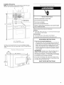
Excessive Weight Hazard
Use two or more people to move and install
microwave oven.
Failure to do so can result in back or other injury.
IMPORTANT: The right side of the microwave oven is the heavy
side. Handle the microwave oven gently.
1. Place awasher on each 1/4-20 x 3" bolt and place inside
upper cabinet near the 3/8" (10 mm) holes.
2. Make sure the microwave oven door is closed and taped shut.
II
J
3. Using 2 or more people, lift microwave oven and hang it on
support tabs at the bottom of mounting plate.
NOTE: To avoid damage to the microwave oven, do not grip or
use the door or door handle while the microwave oven is being
handled.
LI II
A. Mounting plate
B. Support tabs
4=
With front of microwave oven still tilted, thread power supply
cord through the power supply cord hole inthe bottom of the
upper cabinet.
\\
\.
\
5. Rotate microwave oven up toward upper cabinet.
NOTE: If venting through the wall, make sure the damper
assembly fits easily into the vent in the wall cutout.
6. Push microwave oven against mounting plate and hold in
place.
NOTE: If microwave oven does not need to be adjusted, skip
steps 7-9.
7. If adjustment is required, rotate microwave oven downward.
Using 2 or more people, lift microwave oven off of mounting
plate, and set aside on a protected surface.
8. Loosen mounting plate screws. Adjust mounting plate and
retighten screws.
9. Repeat steps 3-6.

10.Withthemicrowaveovencentered,andwithatleastone
personholdingitinplace,insertboltsthroughuppercabinet
intomicrowaveoven.Tightenboltsuntilthereisnogap
betweenuppercabinetandmicrowaveoven.
NOTES:
• Some upper cabinets may require bolts longer or shorter than
3" (7.6 cm). Longer or shorter bolts are available at most
hardware stores.
Overtightening bolts may warp the top of the microwave oven.
To avoid warping, wood filler blocks may be added. The
blocks must be the same thickness as the space between the
upper cabinet bottom and the microwave oven.
A
SSy,, _........................................
A. 1/4-20 x 3" bolts
For Roof Venting Installation Only
1. Insert damper assembly through the cabinet cutout so that the
long tab of the damper assembly slides into the slot on the left
side of the damper vent opening, as shown. Then secure with
mounting screw.
NOTE: The screw cannot be installed if the damper assembly is
not positioned as shown.
B
2. Connect vent to damper assembly.
A B
A. Vent
B. Damper assembly (under vent)
Refer to the Use and Care Guide for instructions on how to
install filters into your model.
Electrical Shock Hazard
Plug into a grounded 3 prong outlet.
Do not remove ground prong.
Do not use an adapter.
Do not use an extension cord,
Failure to follow these instructions can result in death,
fire, or electrical shock.
D
A. Long tab (inside slot)
B. Damper assembly
C. Mounting screw
D. Upper cabinet cutout
2. Plug microwave oven into grounded 3 prong outlet.
3. Reconnect power.
4. Check the operation of microwave oven by placing 1 cup
(250 mL) of water on the turntable, and programming a cook
time of I minute at 100% power. Test vent fan and exhaust by
operating the vent fan.
5. If the microwave oven does not operate:
• Check that a household fuse has not blown, or that a
circuit breaker has not tripped. Replace the fuse or reset
the circuit breaker. If the problem continues, call an
electrician.
• Check that the power supply cord is plugged into a
grounded 3 prong outlet.
• See the Use and Care Guide for troubleshooting
information.
Installation is now complete.
Save Installation Instructions for future use.
10

VENTING DESIGN SPECIFICATIONS
This section is intended for architectural designer and
builder/contractor reference only.
NOTES:
• Vent materials needed for installation are not provided with
microwave hood.
We do not recommend using a flexible metal vent.
Toavoid possible product damage, be sure to vent air outside,
unless using recirculation installation. Do not vent exhaust air
into concealed spaces, such as spaces within walls or
ceilings, attics, crawl spaces or garages.
For optimal venting installation, we recommend:
• using roof or wall caps that have back draft dampers
• using a rigid metal vent
• using the most direct route by minimizing the length of the
vent and number of elbows to provide efficient performance
• using uniformly sized vents
• using duct tape to seal all joints in the vent system
• using caulking compound to seal exterior wall or roof opening
around cap
• not installing 2 elbows together, for optimal hood performance
If venting through the wall, be sure that there is proper clearance
within the wall for the damper to open fully.
If venting through the roof, and rectangular to round transition is
used, be sure there is at least 3" (7.6 cm) of clearance between
the top of the microwave oven and the transition piece. See
"Rectangular to Round Transition" illustration.
Roof venting Roof cap
Wall venting Wall cap
Rectangular to Round Transition
NOTE: The minimum 3" (7.6 cm) clearance must exist between
the top of the microwave oven and the rectangular to round
transition piece so that the damper can open freely and fully.
A. Roof cap
B. 6" (15.2 cm) min. diameter round vent
C. Elbow (for wall venting only)
D. Wall cap
E. 3 ¼" x 10" to 6" (8.3 x 25.4 cm to 15.2cm)
rectangular to round transition piece
E Vent extension piece, at least 3" (7.6 cm) high
Recommended Standard Fittings
The following length equivalents are for use when figuring vent
length. See the examples in "Recommended Vent Length."
A B C
D E G
A. Rectangular to round transition piece: 3¼" x 10" to 6" = 5 ft
(8.3 x 25.4 cm to !5.2 cm = 1.5 m)
B. Roof cap: 3¼" x !0" = 24 ft (8.3 x 25.4 cm = 7.3 m)
C. 90° elbow: 3 ¼" x10" = 25 ft (8.3 x 25.4 cm = 7.6 m)
D. 90° elbow: 6" = lO ft (15.2 cm = 3 m)
E. Wall cap: 3¼" x 10" = 40 ft (8.3 x 25.4 cm = 12.2m)
F. 45 ° elbow: 6" = 5 ft (15.2 cm = 1.5 m)
G. 90° flat elbow: 3 ¼" x lO" = lO ft (8.3 x 25.4 cm = 3 m)
11

Recommended Vent Length
A 31/4"x 10" (8.3 x 25.4 cm) rectangular or 6" (15.2 cm) round vent
should be used.
The total length of the vent system including straight vent,
elbow(s), transitions and wall or roof caps must not exceed the
equivalent of 140 ft (42.7 m)for either type of vent. See
"Recommended Standard Fittings" section for equivalent lengths.
For best performance, use no more than three 90° elbows.
Tocalculate the length of the system you need, add the equivalent
lengths of each vent piece used in the system. See the following
examples:
31/4'' x 10" (8.3 x 25.4 cm) vent system = 73 ft (22.2 m) total
ASSISTANCE
Call your authorized dealer or service center. When you call, you
will need the microwave oven model number and serial number.
Both numbers can be found on the model and serial number
plate, which is located behind the microwave oven door on the
front frame of the microwave oven.
If you need additional assistance, call us at our toll free number or
visit our website listed in the Use and Care Guide.
If any of the installation hardware needs to be replaced, call us at
our toll free number listed in the Use and Care Guide, and
reference the appropriate part number listed here.
A B
Damper Assembly
,_ e. (1.8m) _, Part Number 8206442
"_F I F Mounting Plate
Part Number 8206319
2 ft
....................................................................... Upper Cabinet Template
(°6 m)lU Part Number 8191157
C
A. One 3¼" x 10" (8.3 x 25.4 cm) 90° elbow = 25 ft (7.6 m)
B. 1waft cap = 40 ft (12.2 rn)
C. 2 ft (O.6m) + 6 ft (!.S m) straight = S ft (2.4 rn)
B
6" (15.2 cm) vent system = 73ft (22.2 m) total
I,_ 6 ft (1.8 m)
2 ft
Mounting Screw Kit (includes
parts A-G in "Parts Supplied" in
the "Tools and Parts" section)
Part Number 8206613
Vent Deflector
Part Number 8205980
C D
A. Two 90 ° elbows = 20 ft (6.1 rn)
B. 1 wall cap = 40 ft (!2.2 rn)
C. 1 rectangular to round transition piece = 5 ft (1.5 m)
D. 2 ft (0.6 m) + 6 ft (!.8 m) straight = 8 ft (2.4 m)
If the existing vent is round, a rectangular to round transition piece
must be used. In addition, a rectangular 3" (7.6 cm) extension vent
between the damper assembly and rectangular to round transition
piece must be installed to keep the damper from sticking.
12

P P
SECURITEDE L'ENSEMBLEFOUR A MICRO-ONDES OTTE
Votre s6curit6 et celle des autres est tres importante.
Nous donnons de nombreux messages de securite importants dans ce manuel et sur votre appareil menager. Assurez-vous de
toujours lire tousles messages de securite et de vous y conformer.
Voici le symbole d'alerte de securit&
Ce symbole d'alerte de securite vous signale les dangers potentiels de deces et de blessures graves & vous
et _.d'autres.
Tous les messages de securite suivront le symbole d'alerte de securit6 et le mot "DANGER" eu
"AVERTISSEMENT'. Ces roots signifient :
Risque possible de deces ou de blessure grave si vous ne
euivez pas immediatement lee instructions.
Risque possible de deces ou de blessure grave si vous
ne euivez pas lee instructions.
Tous les messages de securite vous diront quel est le danger potentiel et vous disent comment reduire le risque de blessure et
ce qui peut se produire en cas de non-respect des instructions.
EXIGENCES D'INSTALLATION
Le four a micro-ondes ete configure a I'usine pour une installation avec recyclage. Pour la decharge de I'air aspire a travers lemur ou
travers le toit, voir la section "Specifications du circuit d'evacuation".
Outillage n6cessaire
Rassembler les outils et pieces necessaires avant de commencer A
I'installation. Lire et suivre les instructions fournies avec les outils
mentionnes ici.
• Metre ruban • Detecteur magnetique
(detection des poteaux du
• Crayon colombage)
• Ruban de masquage ou • Cle & douille de 7/16" (ou
punaises cle mixte), pour vis
• Ciseaux d'ancrage de 1/4" x 2"
• Tournevis TORX®tTIO • Scie &trou de 11/2"(3,8 cm)
de diametre pour placard de
• Tournevis Phillips n° 3 (pour bois ou metallique
vis 1/4-20 x3")
• Scie & guichet
• Perceuse electrique
• Pistolet a calfeutrage et
• Meches de 3/16" (5 mm) et compose de calfeutrage
3/8" (10 mm) resistant aux intemperies
• Scie & guichet de 3/4" • Ruban adhesif pour conduit
(19 mm)
• Pince coupante
Pi_ces fournies
Pour la commande de pieces, voir la section "Pieces de
rechange".
REMAROUE : Les articles de quincaillerie presentes ci-dessous
sont destines a I'utilisation sur un colombage de bois. En
presence d'une structure de mur differente, utiliser les organes de
fixation appropries.
S _
H
A. Visa t_te ronde de 1/4-20 x 3" (2)
B. Vis de 1/4-20 x 3" (2)
C. Rendelles (2)
D. £-creus articul_s (2)
E. Vie d'ancrage de 1/4" x 2" (2)
E Vis de t61erie (3)
G. Garniture pour trou de passage du
cordon d'alimentation (1)
H. Module de clapet anti-reflux (pour
d#charge a travers lemur ou le toit)
L D6flecteur (pour d6charge a travers
lemur ou le toit)
Composants non illustr6s :
Gabarit pour placard mural
Plaque de montage (fixation
I'arriere du four a micro-
ondes)
Filtres a graisse en aluminium
Filtres b charbon (selon le
modele, lee filtres a charbon
peuvent ne pas 6tre inclus.
Voir le Guide d'utilisation et
d'entretien.)
REMARQUE :Selon le modele de I'appareil, le filtre &graisse en
aluminium et le filtre a charbon peuvent _tre combines.
Mat6riaux n6cessaires
• Composants standard pour decharge & travers le mur ou
travers le toit. Voir la section "Specifications du circuit
d'evacuation".
1-®TORX est une marque deposee de Textron Innovations Inc.
13

Inspecter I'espace ou le four a micro-ondes sera install&
L'emplacement d'installation dolt disposer de :
• Dimensions minimales & respecter Iors de I'installation. Voir
I'illustration "Dimensions a respecter Iors de I'installation".
• Au moins un poteau de colombage en bois 2" x 4"
(50,8 x 101,6 mm), et parement de pl&tre ou panneau de
gypse d'epaisseur 3/8" (9,5 mm) ou plus, dans I'ouverture du
placard.
• Capacite de support de charge de 150 Ib (68 kg), ceci incluant
le four a micro-ondes et les articles places a I'interieur du four
micro-ondes et du placard mural.
• Prise de courant electrique reliee & la terre a I'interieur du
placard mural. Voir la section "Specifications electriques".
REMARQUES :
• Dans le cas de I'installation du four µ-ondes a proximite
d'une paroi laterale sur le c6te gauche, veiller &laisser un
espace libre de 3" (7,6 cm) ou plus entre lemur et le four
micro-ondes, pour permettre la manceuvre d'ouverture
complete de la porte.
• Les materiaux de certains placards et certains materiaux de
construction ne sont pas congus pour resister &la chaleur
emise par le four a micro-ondes Iors des operations de
cuisson. Consulter le constructeur de la maison ou le fabricant
des placards pour determiner si les materiaux utilises
pourraient subir un changement de couleur, une
destratification ou d'autres dommages.
• Pour une table de cuisson & gaz, on recommande que la
puissance thermique combinee des brQleurs ne depasse pas
50 000 BTU/h.
Le four a micro-ondes a ete configure & I'usine pour
fonctionnement au mode de recyclage. Pour la decharge de
Fair aspire a travers lemur ou a travers le toit, voir la section
"Specifications du circuit d'evacuation".
Exigences sp_ciales
Pour une installation avec d_charge murale seulement :
• L'ouverture decoupee doit _tre exempte d'obstruction pour
I'ajustement adequat du conduit, et pour que le clapet anti-
reflux puisse manceuvrer completement et librement.
Pour une installation avec d_charge _ I'ext_rieur _ travers
le toit seulement :
• S'il est necessaire d'utiliser un raccord de transition, on doit
disposer d'un espace libre de 3" (7,6 cm) au-dessus du four
micro-ondes pour que le clapet anti-reflux puisse manceuvrer
completement et librement. Voir I'illustration "Raccord de
transition rectangulaire/rond" a la section "Specifications du
circuit d'evacuation'.
Dimensions & respecter Iors de I'installation
REMARQUE : La prise de courant a3 alveoles reliee & laterre dolt
_tre situee a I'interieur du placard mural. Voir la section
"Specifications electriques".
A B
69" (175,3 cm) rain.
*33" (83,2 cm) est typique pour une hauteur d'installation de 69"
(175,3 cm). Les dimensions exactes peuvent varier en fonction
du type de cuisiniere/table de cuisson ci-dessous.
18%"
__ 1_14"--'-'--_ 297/8" (76,0 Cm ) -_1
ooo
T
15V2"
14

Risque de choc _lectrique
Brancher sur une prise a 3 aIveoles reli_e a la terre.
Ne pas enlever la broche de liaison a la terre.
Ne pas utiliser un adaptateur,
Ne pas utiliser un c_ble de rallonge,
Le non-respect de ces instructions peut causer
un d_ces, un incendie ou un choc _lectrique.
Observer les dispositions de tous les codes et r_glements en
vigueur.
N6cessaire :
[] Une alimentation electrique de 120 volts, 60 Hz, CA
seulement, 15 ou 20 amperes, protegee par fusibles ou
disjoncteur.
Recommande :
[] Un fusible temporise ou un disjoncteur temporis&
[] Un circuit distinct exclusif ace four a micro-ondes.
INSTRUCTIONS DE LIAISON .&.LA TERRE
[] Pour tout appareil menager connecte par un cordon
de courant electrique :
IIfaut que le four & micro-ondes soit relie & la terre. En
cas de court-circuit electrique, la liaison &la terre reduit le
risque de choc electrique car le courant electrique
dispose d'un itineraire direct d'acheminement & la terre.
Le four µ-ondes est dote d'un cordon de courant
electrique qui comporte un fil de liaison &la terre, avec
broche de liaison & la terre. On dolt brancher la fiche sur
une prise de courant convenablement installee et reliee &
la terre.
AMERTISSEMENT : L'utilisation incorrecte du
dispositif de liaison & la terre peut susciter un risque de choc
electrique. L'utilisateur qui ne comprend pas bien les
instructions de liaison &la terre, ou qui n'est pas certain que
le four & micro-ondes soit convenablement relie & la terre,
devrait consulter un electricien qualifi&
Ne pas utiliser un c&ble de rallonge. Si le cordon de
courant electrique est trop court, demander & un
electricien qualifie d'installer une prise de courant &
proximite du four a.micro-ondes.
CONSERVEZ CES INSTRUCTIONS
INSTRUCTIONS D'INSTALLATION
, _:i_ _ ....... ;..... • .......
REMARQUE : Couvrir la surface de travail pour eviter de
I'endommager.
1. Retirer de la cavit& du four a micro-ondes tousles articles qui
peuvent s'y trouver.
2. Enlever la plaque de montage : enlever les morceaux de ruban
adhesif fixant la plaque de montage sur la face arriere du four
micro-ondes et mettre la plaque de montage de c6t&
REMARQUE : Pour eviter d'endommager le four a micro-ondes,
ne pas prendre prise sur la porte ou la poignee de la porte durant
les manutentions du four a micro-ondes.
Le four a micro-ondes a ete configure a I'usine pour une
installation avec recyclage. Pour la decharge de I'air aspire &
travers lemur ou a travers le toit, on dolt modifier le systeme de
ventilation du four. Voir la section "Specifications du circuit
d'evacuation".
REMARQUE : Pour une installation avec recyclage, ne pas tenir
compte de cette section. Conserver le module du volet de sortie
pour le cas ou la configuration d'installation serait ulterieurement
modifiee ou s'il devenait necessaire de reinstaller le four a micro-
ondes a un autre endroit, avec decharge a I'exterieur a travers le
mur ou a travers le toit.
Pour la preparation du four a micro-ondes pour decharge de I'air
aspire a travers lemur ou le toit, on dolt installer le deflecteur
(_lement metallique en L) et degager I'ouverture appropriee pour
I'installation du volet de sortie.
3=
A B C
A. Plaque de montage
B. Face arriere du four a micro-ondes
C. Ruban adh6sif (en plusieurs endroits)
Utiliser du ruban adhesif pour immobiliser la porte fermee du
four a micro-ondes, pour qu'elle ne puisse pas s'ouvrir durant
les manutentions du four.
15

Installation du d_flecteur :
1. Tirer doucement sur les anneaux pour soulever/enlever la
grille au sommet du four a micro-ondes.
A
2=
B C
A. Sommet du four a micro-ondes
B. Grille de ventilation
C. Anneaux
Alors que le deflecteur est oriente comme sur la figure (lame
large vers le bas), reinserer celui-ci sous la rive arriere de
I'ouverture de sortie.
A B
4. Fixer le deflecteur avec 2 vis de montage (1 a chaque
extremite).
A B
?
A. Vis de montage
B. D_flecteur
5. Reinstaller la grille de ventilation.
Pour une installation avec d_charge murale seulement
D_pose du couvercle de fermeture de la bouche de sortie
(d_charge murale) :
1. Identifier le couvercle de fermeture de la bouche de sortie
pour decharge murale, a I'arriere du four a micro-ondes.
2. Utiliser une pince coupante - decouper doucement les points
de fixation du couvercle de fermeture.
A B C D
3=
A. Ouverture de sortie
B. D_flecteur
Alors que le deflecteur est pousse aussi loin qu'il peut after
I'arriere, le faire basculer pour que la lame large soit a I'arri_re
du four a micro-ondes, et la lame etroite (avec trous) vers le
bas. Les trous du deflecteur doivent s'aligner avec les trous
de montage dans I'ouverture (voir la partie agrandie de
I'illustration).
A B
3=
A. Pince coupante
B. Arriere du four a micro-ondes
C. Couvercle de fermeture de la
bouche de sortie
D. Points de fixation
Conserver le couvercle de fermeture pour le cas ou il serait
necessaire apr_s un changement de configuration ulterieur.
/
A. Ouverturede sortie
B.D_flecteur
16

4. 2. Utiliser une pince coupante - decouper doucement les points
de fixation du couvercle de fermeture.
Positionner adequatement le module du volet de sortie : la
patte Iongue s'ins_re dans la fente du c6te droit de I'ouverture
- voir I'illustration. Fixer le module du volet de sortie avec la vis
de montage.
A B
A. Vis de montage
B. Module du clapet
C. Patte Iongue (dans la fente d'insertion)
Pour une installation avec d_charge & travers le toit
seulement
D_pose du couvercle de la bouche d'installation du volet
de sortie :
1. Identifier le couvercle de fermeture de la bouche de sortie
(pour d_charge &travers le toit, au sommet du four a micro-
ondes).
B C
A. Pince coupante
B. Sommet du four a micro-ondes
C. Couvercle de fermeture de la
bouche de sortie
D. Points de fixation
3. Conserver le couvercle de fermeture pour le cas ou il serait
necessaire apres un changement de configuration ulterieur.
REMARQUE : Ne pas proceder a I'installation du volet de sortie
pour le moment.
REMARQUE : S'il n'y a aucun poteau du colombage dans la zone 1. Utiliser un detecteur magnetique de clou/vis pour Iocaliser
d61imitee par I'ouverture dans le placard mural, ne pas installer le dans I'ouverture les rives des poteaux du colombage mural.
four a micro-ondes. 2. Marquer la position du centre de chaque poteau du
Voir les illustrations & la section "Configurations possibles du colombage, et tracer I'axe de chaque poteau a I'aide d'un fil
colombage mural", plomb. Voir les illustrations & la section "Configurations
possibles du colombage mural".
Configurations possibles du colombage mural
Les illustrations ci-dessous presentent des exemples de configurations pref@entielles d'installation avec la plaque de montage.
Aucun poteau du colombage & la position des trous
des angles
Figure 1
Aucun poteau du colombage _ la position des trous
des angles
Figure 2
, !
C
D
i
oooooo
REMARQUE :Si le poteau mural se trouve &moins de 6"
(15,2 cm) de I'axe central vertical (voir la section "Trace sur le
mur arriere"), seule une installation sans decharge a I'ext@ieur
(recyclage) ou une installation avec decharge par le toit peut
_tre realisee.
17

Un trou d'angle face & un poteau du colombage mural
Figure3
i;
;i
i
;i
i;
I
i
i
i
!
!
I
J
D
Deux trous des angles face & un poteau
du colombage mural
Figure 4
i
A. Trous des angles (sur la plaque de montage)
B.Axe vertical central de I'ouverture clans le placard
C.Axe central de poteau du colombage
D. Trous pour vis d'ancrage
E. Pattes de support
F. Reperes centraux sur la plaque de montage
i
Le four a micro-ondes doit _tre fixe sur au moins un poteau du
colombage mural, et de pref@ence sur 2 poteaux; on utilise pour
cela au moins 1 vis d'ancrage, et de pref6rence 2 vis ou plus.
1. Utiliser un metre-ruban; determiner et marquer clairement la
position de I'axe central vertical de I'ouverture.
A. Axe central
REMARQUE :Si la rive avant du placard mural est plus basse
que la rive arriere, abaisser la plaque de montage de maniere ace
que le sommet de la plaque de montage soit au m_me niveau que
la rive avant du placard.
C
..........................B
2=
AIors que les deux pattes de support sont orientees vers
I'avant (voir les illustrations a la section "Configurations
possibles du colombage mural" a la section "Identifier la
position du/des poteaux du colombage mural"), aligner les
reperes centraux sur la plaque de montage avec I'axe central
sur lemur; veiller au bon aplomb, et veiller ace que lesommet
de la plaque de montage soit en contact contre le bord
inferieur du placard mural.
A. Mur arriere
B. Plaque de montage
C. Le sommet de la plaque de montage doit
_tre align_ avec la rive avant du placard.
D. Rive avant du placard mural
3. Maintenir la plaque de montage en place et marquer la
position des 2 trous des angles.
4. Trouver I'axe central des poteaux du colombage marques
I'etape 2 de la section "Identifier la position du/des poteaux
du colombage mural", et marquer la position d'au moins 1,
et de pref@ence 2, trou(s) a travers la plaque de montage - le
plus pres possible de I'axe central de chaque poteau du
colombage. Voir les figures 1,2 et/ou 3 de la section
"Configurations possibles du colombage mural" a la section
"Identifier la position du/des poteaux du colombage mural".
Les trous a utiliser de pref@ence sont ceux qui sont marques
en noir dans les zones gris_es.
5. Conserver la plaque de montage a part.
18

Pour une installation avec d_charge murale seulement
Axe central_ _ Fond d_ip/l_eard mural
f
4"(10,2cm)
6" (15,2 cm)
> <
6" (15,2 cm)
6. Marquer un point sur I'axe central & 3/8" (1cm) au-dessous de
la rive inferieure du placard mural.
7. Utiliser un metre-ruban; marquer un point a 6" (15,2 cm) de
chaque c6te de I'axe central.
8. Marquer un point a 4" (10,2 cm) au-dessous de la marque
tracee a I'etape 6.
g. Utiliser une regle; tracer 2 lignes horizontales entre les
marques tracees aux etapes 6 et 8.
10. Tracer 2 lignes verticales a partir des marques faites a I'etape
7, pour obtenir un rectangle complet de 12" x 4"
(30,5 x 10,2 cm). Ce rectangle delimite la zone a decouper
pour le passage du conduit d'evacuation.
11. Decouper un trou de 3/4" (19 mm) dans un coin de la zone
decouper.
12. A I'aide d'une scie a guichet, decouper la zone a decouper
pour le passage du conduit d'evacuation.
En plus de la fixation sur au moins un poteau du colombage, on
dolt egalement fixer la plaque de montage sur lemur au niveau
des deux trous des angles inferieurs. Si la position des trous ne
cdlncide pas avec des poteaux du colombage, utiliser deux vis
t_te ronde de 1/4-20 x 3" avec ecrou articule; s'il y a un trou en
cd_ncidence avec les poteaux de colombage, utiliser une vis
d'ancrage et une visa t_te ronde de 1/4-20 x 3" avec ecrou
articule; si les deux trous cd_ncident avec les poteaux de
colombage, utiliser deux vis d'ancrage. On presente ci-dessous 3
configurations d'installation.
Aucun poteau du colombage _ la position des trous des
angles (Figures I et 2)
1. Percer des trous de 3/4" (19 mm) a travers le mur
I'emplacement des deux trous des angles inferieurs marques
I'etape 3 de la section "Trace sur lemur arriere".
2. Percer des trous de 3/16" (5 mm) dans les poteaux de
colombage a I'emplacement des trous marques a I'etape 4 de
la section "Trace sur lemur arriere". Voir lesfigures 1 et 2 dans
le paragraphe "Configurations possibles du colombage
mural" a la section "Identifier la position du/des poteaux du
colombage mural".
Un trou d'angle face & un poteau du colombage mural
(Figure 3)
1. Percer un trou de 3/16" (5 mm) a travers le poteau mural
I'emplacement du trou d'angle marque a I'etape 3 de la
section "Trace sur lemur arriere".
2. S'il est possible de fixer I'appareil sur un second poteau du
colombage mural, percer un trou de 3/16" (5 mm) dans le
poteau du colombage &I'emplacement de I'autre trou marque
I'etape 4 de la section "Trace sur lemur arriere". Voir la
figure 3 darts le paragraphe "Configurations possibles du
colombage mural" a la section "Identifier la position du/des
poteaux du colombage mural".
3. Percer un trou de 3/4" (19 mm) a travers lemur, face a I'autre
trou d'angle.
Deux trous des angles face & un poteau du colombage
mural (Figure 4)
1. Percer des trous de 3/16" (5 mm) a travers les poteaux
muraux a I'emplacement des trous des angles marques
I'etape 3 de la section "Trace sur lemur arriere".
REMARQUE : Fixer la plaque de montage sur le mur; utiliser les
organes de fixation appropries, dans les deux trous des angles
inferieurs perces dans les poteaux du colombage et/ou a travers
le panneau de gypse - vis & t_te ronde de 1/4-20 x 3" avec ecrou
articule ou vis d'ancrage de 1/4 x 2".
Voir les illustrations du paragraphe "Configurations possibles du
colombage mural" & la section "Identifier la position du/des
poteaux du colombage mural".
Aucun poteau du colombage _ la position des trous des
angles (Figures I et 2)
REMARQUE : La plaque de montage dolt _tre fixee sur lemur sur
au moins un poteau de colombage, ainsi qu'aux deux angles
inferieurs.
1. Alors que les pattes de support de la plaque de montage sont
orientees vers I'avant, inserer des vis &t_te ronde de 1/4-20 x
3" dans les deux trous des angles inferieurs de la plaque de
montage.
2. Engager un ecrou articule sur chaque vis par I'arriere de la
plaque de montage. Veiller a disposer de suffisamment
d'espace pour que I'ecrou articule puisse traverser le panneau
de gypse et se deployer a I'interieur de la cavite murale.
A
A. Visa t_te ronde de 1/4-20x 3"
B. Plaque de montage
C. Ecrou articul_
3. Positionner la plaque de montage sur lemur; veiller a ce que
le sommet de la plaque de montage soit aligne avec la rive
avant du placard mural.
19

4=
Pousser les deux vis avec ecrou articule &travers le panneau
de gypse; visser les visa la main pour verifier que chaque
ecrou articule s'est deploy6 et prend appui contre le panneau
de gypse.
C
//
//
A. Visa t#te ronde de 1/4-20x 3"
B.Plaque de montage
C.Panneaude gypse
D.Ecrou articul_
5. Inserer les vis d'ancrage dans les trous perces darts les
poteaux de colombage & I'etape 2 du paragraphe "Aucun trou
des angles en cdlncidence avec les poteaux du colombage"
de la section "Pergage des trous dans lemur arriere".
6. Contr61er I'alignement de la plaque de montage; veiller &
etablir un bon aplomb.
7. Serrer solidement les vis d'ancrage et les boulons.
Un trou d'angle face _ un poteau du colombage mural
(Figure 3}
1. AIors que les pattes de support de la plaque de montage sent
orientees vers I'avant, inserer une visa t_te ronde de 1/4-20 x
3" dans le trou d'angle coincidant avec le trou de 3/4" (19 mm)
perce a I'etape 3 du paragraphe "Un trou des angles inferieurs
en cdlncidence avec les poteaux du colombage" de la section
"Pergage des trous dans lemur arriere".
2. Engager un ecrou articule sur la vis par I'arriere de la plaque
de montage. Veiller a disposer de suffisamment d'espace
pour que I'ecrou articule puisse traverser le panneau de gypse
et se deployer a I'interieur de la cavite murale.
3. Positionner la plaque de montage sur le mur; veiller ace que
le sommet de la plaque de montage soit aligne avec la rive
avant du placard mural.
4. Pousser la vis avec ecrou articule a travers le panneau de
gypse; visser la visa la main pour verifier que chaque ecrou
articule s'est deploye et prend appui contre le panneau de
gypse.
5. Inserer une vis d'ancrage dans le trou d'angle inferieur restant.
6. S'il est possible de fixer egalement I'appareil sur un second
poteau du colombage mural, inserer une vis d'ancrage dans
I'autre trou perce a I'etape 2 du paragraphe "Un trou des
angles inferieurs en cdfncidence avec les poteaux du
colombage" de la section "Per(_age des trous dans lemur
arriere'.
7. Contr61er I'alignement de la plaque de montage; veiller
etablir un bon aplomb.
8. Serrer solidement la/les vis d'ancrage et le boulon.
Deux trous des angles face & un poteau du colombage
mural (Figure 4)
1. Positionner la plaque de montage sur lemur; veiller ace que
le sommet de la plaque de montage soit aligne avec la rive
avant du placard mural.
2. Inserer les vis d'ancrage dans les deux trous des angles
inferieurs.
3. Contr61er I'alignement de la plaque de montage; veiller
etablir un bon aplomb.
4. Serrer solidement les vis d'ancrage.
1=
2.
3.
..........._:................_................ _;1 _ ;__:
Interrompre I'alimentation electrique.
Retirer tout le contenu du placard mural.
Placer le gabarit "placard mural" contre le fond du placard
mural, et le fixer avec du ruban adhesif ou des punaises.
Veiller a aligner I'axe central du gabarit avec I'axe vertical
central trace sur lemur arriere.
Les fleches "rear wall/mur arriere" doivent _tre contre lemur
arriere, pour qu'on puisse obtenir I'alignement des trous
decoup&s dans le placard mural avec les trous situes au
sommet du four a micro-ondes.
REMARQUE :Si le placard mural comporte un cadre
perimetrique, tailler les bords du gabarit de telle maniere qu'il
puisse s'ajuster dans le cadre, contre le fond du placard mural. Le
gabarit comporte des lignes de decoupe qu'on peut utiliser
comme guides.
4. Veiller a etablir la dimension de 10W' (25,4 cm) entre le mur
arriere et les points "D" et "E" sur le gabarit.
O
I
I
I
I
I
5. Percer le trou de diametre 1V_"(3,8 cm) dans la zone circulaire
grisee "G" du gabarit. C'est le trou utilise pour le passage du
cordon d'alimentation.
REMARQUE : Si le placard mural est metallique, la garniture de
cordon d'alimentation necessite d'etre installee autour du trou de
passage du cordon d'alimentation - voir I'illustration.
A. Placard m_tallique
B. Garniture du trou de passage du cordon d'alimentation
6. Percer des trous de 3/8" (10 mm) aux points "D" et "E" du
gabarit. Ces trous sont utilises pour le passage de deux vis de
1/4-20 x 3" avec rondelle, utilisees pour la fixation du four
micro-ondes contre le placard mural.
Pour une installation avec d_charge _ I'ext_rieur
travere le toit seulement
7. Decouper un trou de 3/4" (19 mm) dans un coin de la zone
ombree rectangulaire "F" sur le gabarit "Placard mural".
8. ,A,I'aide d'une scie a guichet, decouper la zone rectangulaire.
20
La page charge ...
La page charge ...
La page charge ...
La page charge ...
-
 1
1
-
 2
2
-
 3
3
-
 4
4
-
 5
5
-
 6
6
-
 7
7
-
 8
8
-
 9
9
-
 10
10
-
 11
11
-
 12
12
-
 13
13
-
 14
14
-
 15
15
-
 16
16
-
 17
17
-
 18
18
-
 19
19
-
 20
20
-
 21
21
-
 22
22
-
 23
23
-
 24
24


KitchenAid YKHMS2050SB0 Guide d'installation
- Taper
- Guide d'installation
- Ce manuel convient également à
dans d''autres langues
Documents connexes
Autres documents
-
IKEA IMH15XVQ5 Guide d'installation
-
Inglis IRH32000 Guide d'installation
-
IKEA YMH1170XSS1 Guide d'installation
-
Maytag W10191953A Manuel utilisateur
-
IKEA YWMH1162XVS1 Guide d'installation
-
-
Whirlpool YMH6140XFQ2 Guide d'installation
-
Whirlpool YMH1141XMQ1 Guide d'installation