
1
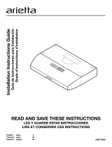
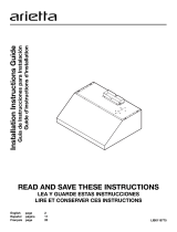
Use, Care, and
Installation Guide
Guide
d’utilisation,
d’entretien et
d’installation
Guía de
instalación, uso y
mantenimiento
READ AND SAVE THESE
INSTRUCTIONS
LISEZ CES
INSTRUCTIONS ET
CONSERVEZ-LES
LEA Y CONSERVE
ESTAS INSTRUCCIONES
LIB0139633
Printed in Mexico
12/17
Models: EMD530S3
EMD536S3

2
ENGLISH
Contents
Important safety notice................................................................................................................................................................................................. 3
List of materials............................................................................................................................................................................................................... 4
Parts supplied ............................................................................................................................................................................................................. 4
Parts not supplied ..................................................................................................................................................................................................... 4
Dimensions and clearances......................................................................................................................................................................................... 5
Ducting options and examples.................................................................................................................................................................................. 5
Installation ......................................................................................................................................................................................................................... 8
Electrical connection................................................................................................................................................................................................ 10
Complete the installation........................................................................................................................................................................................ 10
Description of the hood................................................................................................................................................................................................ 10
Control................................................................................................................................................................................................................................. 10
Maintenance ..................................................................................................................................................................................................................... 11
Warranty ........................................................................................................................................................................................................................... 12
APPROVED FOR RESIDENTIAL APPLIANCES
FOR RESIDENTIAL USE ONLY
READ AND SAVE THESE INSTRUCTIONS
PLEASE READ ENTIRE INSTRUCTIONS BEFORE PROCEEDING.
INSTALLATION MUST COMPLY WITH ALL LOCAL CODES.
IMPORTANT: Save these Instructions for the Local Electrical Inspector’s use.
INSTALLER: Please leave these Instructions with this unit for the owner.
OWNER: Please retain these instructions for future reference.
Safety Warning: Turn o power circuit at service panel and lock out panel, before wiring this appliance.
Requirement: 120 V AC, 60 Hz. 15 or 20 A Branch Circuit.

3
I
IMPORTANT SAFETY NOTICE
I CAUTION
FOR GENERAL VENTILATING USE ONLY. DO NOT USE TO
EXHAUST HAZARDOUS OR EXPLOSIVE MATERIALS OR
VAPOURS.
I WARNING
TO REDUCE THE RISK OF FIRE, ELECTRIC SHOCK, OR
INJURY TO PERSONS, OBSERVE THE FOLLOWING:
A. Use this unit only in the manner intended by the
manufacturer. If you have questions, contact the
manufacturer.
B. Before servicing or cleaning the unit, switch power o
at service panel and lock service panel disconnecting
means to prevent power from being switched on
accidentally.
When the service disconnecting means cannot be
locked, securely fasten a prominent warning device,
such as a tag, to the service panel.
C. Installation work and electrical wiring must be done by
qualified person(s) in accordance with all applicable
codes & standards, including fire-rated construction.
D. Sucient air is needed for proper combustion and
exhausting of gases through the flue (Chimney) of fuel
burning equipment to prevent back- drafting.
Follow the heating equipment manufacturers guideline
and safety standards such as those published by the
national fire protection association (NFPA), the american
society for heating, refrigeration and air conditioning
engineers (ASHRAE), and the local code authorities.
E. When cutting or drilling into wall or ceiling, do not
damage electrical wiring and other hidden utilities.
F. Ducted systems must always be vented to the outdoors.
I CAUTION
To reduce risk of fire and to properly exhaust air, be sure to
duct air outside - do not vent exhaust air into spaces within
walls, ceilings, attics, crawl spaces, or garages.
I WARNING
TO REDUCE THE RISK OF FIRE, USE ONLY METAL DUCT
WORK.
Install this hood in accordance with all requirements specified.
I WARNING
To reduce the risk of fire or electric shock, do not use this
hood with any external solid state speed control device.
I WARNING
TO REDUCE THE RISK OF A RANGE TOP GREASE FIRE.
a) Never leave surface units unattended at high settings.
Boilovers cause smoking and greasy spillovers that may
ignite. Heat oils slowly on low or medium settings.
b) Always turn hood ON when cooking at high heat or when
flambeing food (I.e. Crepes Suzette, Cherries Jubilee,
Peppercorn Beef Flambe’).
c) Clean ventilating fans frequently. Grease should not be
allowed to accumulate on fan or filter.
d) Use proper pan size. Always use cookware appropriate
for the size of the surface element.
I WARNING
TO REDUCE THE RISK OF INJURY TO PERSONS, IN THE
EVENT OF A RANGE TOP GREASE FIRE, OBSERVE THE
FOLLOWING:
a
a) SMOTHER FLAMES with a close-fitting lid, cookie sheet,
or other metal tray, then turn o the gas burner or the
electric element. BE CAREFUL TO PREVENT BURNS. If the
flames do not go out immediately, EVACUATE AND CALL
THE FIRE DEPARTMENT.
b) NEVER PICK UP A FLAMING PAN - you may be burned.
c) DO NOT USE WATER, including wet dishcloths or towels -
a violent steam explosion will result.
d) Use an extinguisher ONLY if:
1) You know you have a class ABC extinguisher, and
you already know how to operate it.
2) The fire is small and contained in the area where it
started.
3) The fire department is being called.
4) You can fight the fire with your back to an exit.
e) Ducted fans must always be vented to the outdoor.
a
Based on “Kitchen Fire Safety Tips” published by NFPA.
I CAUTION
Automatically Operated Device - To Reduce The Risk Of
Injury Disconnect From Power Supply Before Servicing.

4
LIST OF MATERIALS
Removing the packaging.
I CAUTION
Remove carton carefully, wear gloves to protect against sharp edges.
I WARNING
Remove the protective film covering the product before putting into operation.
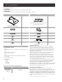
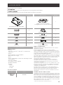
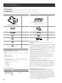
Supplied Part Pieces Supplied Part Pieces
Hood assembly and
LED lamps already installed
1
Rectangular duct 3
1
⁄4” x 10” (8.3 x 25.4 cm)
with back draft dampers
1
5.4x75 mm
6
6” round air transition
1
5x45 mm
6
Torx 20 adapter
1
4x8 mm
4
8x40 mm
6
4.5x13 mm
4
10x60 mm wall anchors
6
3.5x9.5 mm
3
Ø 6.4x18 mm washers
2
Parts not supplied
Tools/Materials required
• Level
• Drill with 1
1
⁄4” (3.0 cm),
1
⁄8” (3.0 mm),
1
⁄16” (4.8 mm) drill bits
• Pencil
• Wire stripper or utility knife
• Tape measure or ruler
• Pliers
• Caulking gun and weatherproof caulking compound
• Vent clamps
• Saber or keyhole saw
• Metal snips
• Screwdrivers:
- Phillips
- Flat-blade
- Torx #10
Optional accessories and consumable parts
KIT # Part
Charcoal filter
replacement
Kit
KIT02667
Location requirements:
IMPORTANT: Observe all governing codes and ordinances.
Have a qualified technician install the range hood. It is the
installer’s responsibility to comply with installation clearances
specified on the model/serial rating plate. The model/serial
rating plate is located inside the liner behind the filter on the
left wall of the range hood.
Range hood location should be away from strong draft areas,
such as windows, doors, and strong heating vents.
Cabinet opening dimensions that are shown must be used.
Given dimensions provide minimum clearance. Consult your
cooktop/ range manufacturer installation instructions before
making any cutouts. Grounded electrical outlet is required.
See “Electrical Requirements” section.
The range hood is factory set for vented installations through
the roof or wall. For non-vented (recirculating) installations
see “Non- Vented (recirculating) Installation Through the
Soffit/Cabinet” in the “Prepare Location” section.
Recirculation Kit Part is available from your dealer or an authorized
parts distributor. All openings in ceiling and wall where range
hood will be installed must be sealed.
For mobile home installations
The installation of this range hood must conform to the
Manufactured Home Construction Safety Standards, Title 24
CFR, Part 328 (formerly the Federal Standard for Mobile Home
Construction and Safety, title 24, HUD, Part 280) or when such
standard is not applicable, the standard for Manufactured Home
Installation 1982 (Manufactured Home Sites, Communities and
Setups) ANSI A225.1/NFPA 501A, or latest edition, or with local
codes.
†®TORX is a registered trademark of Saturn Fasteners, Inc.

5
LOCATION REQUIREMENTS
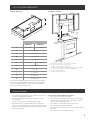
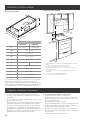
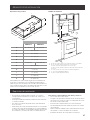
Product dimensions
E
F
B
K
A
C
G
H
I
J
D
Models
EMD530S3 EMD536S3
A 30” (76 cm) 36” (91.2 cm)
B 19
5
⁄8” (50 cm)
C 9
3
⁄4” (25 cm)
D 2⁄” (5.5 cm)
E 1
10
⁄16” (4 cm)
F 3” (7.6 cm) 5¾” (14.6 cm)
G 13
13
⁄16” (35 cm)
H
5
⁄8” (1.6 cm)
I 1
3
⁄16” (3 cm)
J 7
1
⁄4” (18.4 cm)
K 12” (30.5 cm)
For gas range installation: Mount this hood so that the bottom
edge is at minimum 27”(68.6 cm) above the cooking surface.
For electric range installation: mount this hood so that the
bottom is not less than 24”(61 cm).
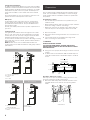
Installation clearances
C
B
D
E
A
A. 18” (45.7 cm) min. clearance - upper cabinet to countertop
B. 24” (61 cm) min. for electric cooking surfaces
27” (68.6 cm) min. for gas cooking surfaces
36” (91.4 cm) suggested max. - bottom of range hood to cooking surface
C. 30” or 36” (76.2 cm or 91.4 cm) min. cabinet opening width
D. 12” (30.5 cm) cabinet depth
E. 36” (91.4 cm) base cabinet height
Ducting Options
• Vent system must terminate to the outdoors, except for no
vented (recirculating) installations.
• Do not terminate the vent system in an attic or other
enclosed area.
• Do not use a 4” (10.2 cm) laundry-type wall cap.
• Rigid metal vent is recommended. Plastic or metal foil
vent is not recommended. The length of vent system and
number of elbows should be kept to a minimum to provide
ecient performance.
For the most ecient and quiet operation:
• Use no more than three 90° elbows.
• Make sure there is a minimum of 24” (61 cm) of straight
vent between the elbows if more than 1 elbow is used.
• Do not install 2 elbows together.
• Use clamps to seal all joints in the vent system.
• The vent system must have a damper.
• Use caulking to seal exterior wall or roof opening around
the cap.
• The size of the vent should be uniform.

6
Cold weather installations
An additional back draft damper non return valve should be
installed to minimize backward cold air flow and a thermal
break should be installed to minimize conduction of outside
temperatures as part of the vent system. The damper non
return valve should be on the cold air side of the thermal
break.
The break should be as close as possible to where the vent
system enters the heated portion of the house.
Makeup air
Local building codes may require the use of makeup air
systems when using ventilation systems with greater than
specified CFM of air movement. The specified CFM varies
from locale to locale.
Consult your HVAC professional for specific requirements in
your area.
Venting methods
Vent system can terminate either through the roof or wall.
Use 3
1
⁄4” x 10” (8.3 x 25.4 cm) with a maximum vent length
of 35 ft (10.7 m) or 6” (15.2 cm) or larger round vent with a
maximum length of 50 ft (15.2 m) for vent system.
In cases where it should not be possible to discharge cooking
fumes and vapour to the outside, purchase Charcoal Filter
Replacement Kit.
NOTE: Flexible vent is not recommended. Flexible vent
creates back pressure and air turbulence that gently reduces
performance.
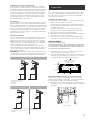
Vertical Discharge
C
B
A
B
D
A
A. 6” (15.2 cm) round transition
B. 6”(15.2 cm) duct
C. Cabinet
D. 90° elbow
Horizontal Discharge Recirculating
B
A
C
A. 3
1
⁄4” x 10” (8.3 x 25.4 cm)
rectangular transition
B. 3
1
⁄4” x 10” (8.3 x 25.4 cm) duct
C. Cabinet
A
B
A. Cabinet
B. Charcoal filters
Preparation
We recommend that a qualified technician install the range
hood. It is the installer’s responsibility to ensure the range
hood complies with the installation clearances specified for
the product.
Preparing the location
• We recommend you install the vent system before you
install the hood.
• Before making cutouts, make sure there is proper clearance
within the ceiling or wall for vent fittings.
• Making the cutout to the bottom of the cabinet may be
easier to do prior to mounting the cabinet to the wall.
1 Disconnect power.
2 Determine which venting method to use: roof, wall or non
vented.
3 Select a flat surface for assembling the range hood.
Place a covering over that surface.
I WARNING:
EXCESSIVE WEIGHT HAZARD
USE TWO OR MORE PEOPLE TO MOVE AND INSTALL
RANGE HOOD. FAILURE TO DO SO CAN RESULT IN BACK
OR OTHER INJURY.
4 Using 2 or more people, lift the range hood onto covered
surface.
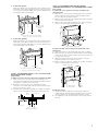
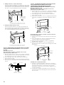
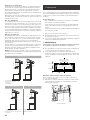
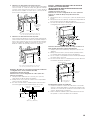
5 If cabinet has recessed bottom, add wood filler strips on
each side. Install screws to attach filler strips in locations
shown.
Wood filler strips
(recessed cabinet
bottoms only)
Cabinet
bottom
Wall
3” (7.6 cm)
CL
30”model: 13⁄”(35cm)
36”model: 16⁄”(42.5cm)
30”model: 13⁄”(35cm)
36”model: 16⁄”(42.5cm)
3” (7.6 cm)
Determine wiring hole location
Cut only one 1
1
⁄4” (3.2 cm) diameter wiring access hole. See
Step 2 for wiring hole location instructions.
1 Determine and clearly mark a vertical centerline on the
wall and cabinet in the area the vent opening will be
made.
A
A. Centerline

7
2. To wire through top:
Mark a line distance “A” from the left of the centerline on the
underside of the cabinet. Mark the point on this line that is
1⁄” (4 cm) from back wall. Drill a 1¼” (3.2 cm) diameter hole
through the cabinet at this point.
A
Centerline
1⁄” (4 cm) from
wall, not cabinet
frame
A. 12” (30.5 cm) for 30” (76.2 cm) models
12¼” (31.1 cm) for 36” (91.4 cm) models
3. To wire through wall:
Mark a line distance “A” from the left of the centerline on the
underside of the cabinet. Mark a point on this line that is 1”
(2.54 cm) from back wall. Drill a 1¼” (3.2 cm) diameter hole
through the cabinet at this point.
Centerline
A
1” (2.5 cm)
A. 12” (30.5 cm) for 30” (76.2 cm) models
12¼” (31.1 cm) for 36” (91.4 cm) models
STYLE 1 - CUT OPENINGS FOR 3¼” X 10” (8.3 CM X 25.4 CM)
RECTANGULAR VENT SYSTEM
Wall venting
To make a 4” x 10½” (10.2 cm x 26.7 cm) rectangle in the wall:
1 Draw one line 2
3
⁄4” (7.0 cm) and a second line 6
3
⁄4” (17.1
cm) below the underside of the cabinet. Extend these lines
through the centerline on the back wall.
2 Draw lines 5¼” (13.3 cm) to the right and left of the
centerline on the wall. Make sure these lines intersect with
the lines you drew in Step 1.
3 With the lines you drew as a guide, use a saber or keyhole
saw to cut a rectangular opening in the wall for the vent.
Centerline
Cabinet
front
2
3
⁄4” (7.0 cm)
6
3
⁄4” (17.1 cm)
5
1
⁄4”
(13.3 cm)
5
1
⁄4”
(13.3 cm)
STYLE 2 - CUT OPENINGS FOR TOP VENT OUTLET
(FROM RECTANGULAR TO 6” (15.2 CM) ROUND VENT SYSTEM)
Roof venting
To make a 6
1
⁄2” x 8½” (16.5 cm x 21.6 cm) rectangle in the
cabinet bottom:
1 Draw a line ½” (1.3 cm) from the back wall on the centerline
of the underside of the cabinet, and then draw another
line 6½” (16.5 cm) from the first line.
2 Draw lines 4¼” (10.8 cm) to the right and left of the centerline
on the underside of cabinet.
3 With the lines you drew as a guide, use a saber or keyhole
saw to cut a rectangular opening for the vent.
*From wall, not cabinet frame
To make a circular vent opening on the underside of the
cabinet top:
1 Draw a centerline on the underside of the top of cabinet.
2 Draw a line 3
7
⁄8” (9.7 cm) from the back wall on the underside
of the top of cabinet. Make sure the line intersects with the
line you drew in Step 1.
3 Where the two lines intersect, use a compass or a circle
template to draw a 6¼” (15.2 cm) circle.
4 With the circle you drew as a guide, use a saber or keyhole
saw to cut the circular vent opening.
*From wall, not
cabinet frame
Cabinet
cutouts
*3⅞”
(9.7 cm)
Circular vent opening
6
1
⁄4”
15.8 cm
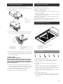
Install vent system
1 Install the vent through the vent opening in cabinet or
wall. Complete venting system according to the selected
venting method. See “Venting Requirements” section.
2 Use caulking to seal exterior wall or roof opening around
the cap.

8
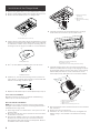
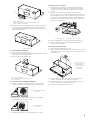
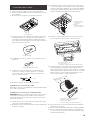
Installation of the Range Hood
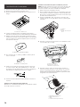
1 Remove the grease filters. See the “Maintenance” section.
2 Remove foam shipping pad from behind the blower motor.
3 Remove the left stainless piece, see image below.
A
A. Left stainless piece screws (2)
4 Lift the range hood up under cabinet and determine it´s final
location by centering beneath cabinet. Mark on the underside
of cabinet the location of the 4 keyhole mounting slots on
the range hood. Set range hood aside on a covered surface.
A
A. Keyhole slot
5 Use
1
⁄8” (3 mm) drill bit and drill 4 pilot holes as shown.
A
A. Drill pilot hole
6 Install the 4 - 4.5 x 13 mm mounting screws in pilot holes.
Leave about
1
⁄4” (6.4 mm) space between screw heads and
cabinet to slide range hood into place.
1
⁄4” (6.4 cm)
7 Replace the left stainless piece removed previously in step 3.
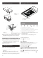
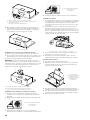
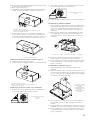
Vent connector installation
Determine whether the range hood will be installed using
either a top or rear vent connection.
Rear vent transition installation
NOTE: For rear venting, the blower motor position must be
changed. It will need the rear motor mounting bracket that is
included with the range hood.
1 Place range hood on its back. Fit the vent system over the
exhaust outlet.
2 Disconnect the blower motor electrical connector from the
electrical box connector.
3 Using a T20® adapter, remove the 4 screws holding the
blower motor in place. Push up on the blower motor to
disengage the tabs from range hood cavity back. Remove
the blower motor and set it aside.
C
B
A
A. Range hood canopy
(inside top)
B. Blower motor
C. Blower motor mounting
screws
4 Install the rear blower mounting bracket into the range
hood and secure it with the (4) 4 x 8 mm screws.
A
B
C
B
A. Range hood canopy (inside back)
B. 4 x 8 mm screws (4)
C. Rear blower motor mounting bracket assembly
5 Install the blower motor onto the rear motor mounting
bracket (included with the range hood). Engage the motor
mounting tabs with the keyhole slots in the rear mounting
bracket and push down to secure. Install the 4 screws
removed previously and tighten to secure motor bracket.
A
B
C
D
A. Rear motor mounting bracket
B. Motor mounting tabs (2)
C. Blower motor
D. Blower motor mounting screws (4)
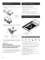
6 Reconnect blower motor electrical connector to the electrical
box connector.
7 Remove the rear vent knockout.
8 Attach the 3
1
⁄4” x 10” (8.3 cm x 25.4 cm) rectangular vent
damper using 3- 3.5 x 95 mm vent transition mounting
screws.

9
C
B
A
A. Rear vent knockout
B. Rear rectangular transition knockout mounting screws (3)
C. Rear rectangular vent transition
9 Remove one of the round knockout from the top or back
of the range hood (depending on your wiring location)
for the wiring strain relief and install a
1
⁄2” UL listed or CSA
approved strain relief.
A
A. Round knockout
Top vent transition installation
1 Remove the top vent knockout.
2 Attach the round vent transition damper using 2-3.5 x 9.5 mm
vent transition mounting screws.
3 Remove tape from damper flap.
A
C
B
A. Top round vent transition
B. Top round vent transition mounting screws (2)
C. Top vent knockout
For non-vented (recirculating) installations
1 Remove the blower mounting screws. Push up on the
blower to detach the blower from the mounting plate.
A
B
A. Front mounting plate knockout
B. Blower
2 Rotate the blower and attach to front mounting plate.
Install the blower mounting screws
A
B
A. Front mounting plate
B. Blower
3 Install charcoal filters. See the “Maintenance” section.
Install range hood to cabinet
1 Using 2 people, lift range hood into final location. Feed
enough electrical wire through the strain relief to make
connections in the terminal box. Tighten the strain relief
screws.
2 Position the range hood so that the large end of the
keyhole slots are over the mounting screws. Then push the
hood toward the wall so that the screws are in the neck of
the slots. The hood should be against the wall. Tighten the
mounting screws, making sure mounting screws are in the
narrow neck of the slots.
A
B
C
A. 4- mounting screws B. Security screws C. Washers
3 Check that damper, if used, rotates up and down freely.
4 Connect ventwork to hood. Seal joints with clamps to
make secure and airtight.
Install range hood to the wall
1 Fix the wiring conduit of the hood.
2 Slide the hood back against the wall. Tighten the mounting
screws. Be sure the screw heads are in the narrow neck of
the keyhole slot.
A
C
B
B
D
A. Mounting screws
B. Upper security screws
(Wall Installation)
C. Lower security screws
(Wall Installation)
D. Washers
3 Insert 2 screws into the upper security screw locations
(see B in the image above). Tighten the screws.
4 Insert 2 screws into the lower security screw location (see
C in the image above). Tighten the screws.
5 5. Connect the Ductwork to the hood.

10
Electrical Connection
1 Disconnect power.
2 Remove the bracket and then the terminal box cover.
A
B
D
C
B
A. Bracket
B. Terminal box screws
C. Terminal box cover
D. Terminal box
3 Remove the knockout in the terminal box cover and install
a UL listed or CSA approved
1
⁄2” strain relief.
E
F
A
B
C
D
A. White wires
B. Black wires
C. UL listed wire connectors
D. Green (or bare) and yellow-green ground
wire
E. Home power supply cable
F. UL listed or CSA approved ½” strain relief
4 Use UL listed wire connectors and connect the black wires
(B) together. Use UL listed wire connectors and connect
the white wires (A) together.
I WARNING:
ELECTRICAL SHOCK HAZARD. ELECTRICALLY GROUND
BLOWER. CONNECT THE GROUND WIRE TO THE GREEN AND
YELLOW GROUND WIRE IN THE TERMINAL BOX. FAILURE
TO DO SO CAN RESULT IN DEATH OR ELECTRICAL SHOCK.
5 Connect the green (or bare) ground wire from the home
power supply to the yellow-green ground wire (D) in the
terminal box using UL listed wire connectors.
6 Install the terminal box cover.
7 Reconnect the power.
Complete Installation
Replace filters. Check operation of the hood.
If range hood does not operate:
• Check that the circuit breaker is not tripped or the house
fuse blown.
• Disconnect power supply. Check that wiring is correct.
To get the most ecient use from your new range hood, read
the “Maintenance” section. Keep your Installation Instructions
and Use and Care Guide close to range hood for easy reference.
Description of the Hood
2
4
1
3
1. Blower and light controls
2. LED lamps
3. Grease filter handle
4. Grease filter
Control
1 2 3 4 5 6
1. Button ON/OFF motor (stand by)
2. Button for low speed (suction power) selection
When flashing, it indicates that you must wash the grease filter.
3. Button for medium speed (suction power) selection
4. Button for high speed (suction power) selection
5. Button for intensive speed (suction power) selection
It lasts 5 minutes then it returns to medium speed (suction power).
6. Button ON/OFF lighting
Press briefly to switch on or o the lighting of the hood.
Press and hold to adjust the intensity of the light.
Indicators of filter saturation:
At regular time intervals, the hood indicates the need of
performing filter maintenance.
Button on with steady light:
Perform grease filter maintenance.
Button flashing:
Perform activated charcoal filter maintenance.
NOTE: Filter saturation signal is visible within the first minute
after switching off the hood; within this time, the reset of
saturation indicators must be performed.
Reset of filter saturation indicators:
Press and hold the button
Activation of saturation indicator activated charcoal filter:
NOTE: This operation must be performed with the hood off.
This indicator is normally deactivated; press and hold the
button to activate the function: the button lights up with
steady light.
To deactivate the function, press and hold the button ,
the button lights up flashing.

11
CFM Reduction System
Before operating your hood:
Some States and Provinces of the US & Canada restrict the
maximum exhausting airflow of range hoods. Airflow is measured
as cubic feet per minute (CFM). These maximum levels allowed
are detailed in the local code of your area. Please check local
codes to find out if you need to restrict the maximum airflow
of your hood. If your local code mandates a maximum airflow
level below the maximum airflow of this hood (i.e. 600 CFM),
please execute the procedure below to reduce the maximum
airflow.
1
5
1 Turn the motor OFF.
2 Press the ON/OFF (1) and Intensive speed (5) buttons
together for 3 seconds.
You will hear a beep and all control lights will illuminate
for 3 seconds.
This action will Disable speeds 3 and 4 and eectively
lower the Maximum airflow to > 300 CFM.
3 Locate the CFM certification sticker in the hardware pack.
4 Peel and Ax this sticker to a visible area in the blower.
This sticker provides ocial certification to your local
inspector that this hoods maximum airflow has been
reduced to > 300 CFM.
Maintenance
Cleaning
Do not spray cleaners directly to the control while cleaning the
Hood. The cooker hood should be cleaned regularly (at least
with the same frequency with which you carry out maintenance
of the fat filters) internally and externally. Clean using the
cloth dampened with neutral liquid detergent. Do not use
abrasive products. DO NOT USE ALCOHOL!
I WARNING:
Failure to carry out the basic cleaning recommendations of the
cooker hood and replacement of the filters may cause fire risks.
Therefore, we recommend oserving these instructions.
The manufacturer declines all responsibility for any damage to
the motor or any fire damage linked to inappropriate maintenance
or failure to observe the above safety recommendations.
Grease filter
Traps cooking grease particles.
This must be cleaned once a month using non aggressive
detergents, either by hand or in the dishwasher, which must be
set to a low temperature and a short cycle. When washed in
a dishwasher, the grease filter may discolour slightly, but this
does not affect its filtering capacity.
To remove the grease filter, pull the spring release handle.
A
A. Spring release handle
Replacing a LED lamp
The LED lights are replaceable by a service technician only.
See “Who to contact” section in the warranty for service
contact information.
Charcoal filter
I WARNING
To reduce the risk of fire and shock use only the carbon filter kit
KIT02667.
If the model is not vented to the outside, the air will be
recirculated through disposable charcoal filters that help
remove smoke and odors.
1 Cover the grill that protects the suction motor with the
carbon filter so that the slots on the filter correspond to
the pins on the sides of the motor protection grill.
2 Turn the carbon filter clockwise to block them (bayonet
fixing).
NOTE: Remove the wiring to be able of placing the charcoal
filter and then replace it.
NOTE: The charcoal filters cannot be cleaned. It should be
replaced every 4-6 months (depending on hood usage).
NOTE: DO NOT rinse, or put charcoal filters in an automatic
dishwasher.
NOTE: Charcoal filters are not included with the hood. They
must be ordered from your supplier. Order the needed kit
specifying your hood model and width size.

12
ELICA North America
TWO-YEAR LIMITED WARRANTY
TO OBTAIN SERVICE UNDER WARRANTY
Owner must present proof of original purchase date. Please keep a copy of your dated proof of purchase (sales slip) in
order to obtain service under warranty.
PARTS AND SERVICE WARRANTY
For the period of two (2) years from the date of the original purchase, Elica will provide free of charge, non consumable
parts or components that failed due to manufacturing defects. During these two (2) years limited warranty, Elica will also
provide free of charge, all labor and in-home service to replace any defective parts.
WHAT IS NOT COVERED
• Damage or failure to the product caused by accident or act of God, such as, flood, fire or earthquake.
• Damage or failure caused by modification of the product or use of non-genuine parts.
• Damage or failure to the product caused during delivery, handling or installation.
• Damage or failure to the product caused by operator abuse.
• Damage or failure to the product caused by dwelling fuse replacement or resetting of circuit breakers.
• Damage or failure caused by use of product in a commercial application.
• Service trips to dwelling to provide use or installation guidance.
• Light bulbs, metal or carbon filters and any other consumable part.
• Normal wear of finish.
• Wear to finish due to operator abuse, improper maintenance, use of corrosive or abrasive cleaning products/pads and
oven cleaner products.
WHO IS COVERED
This warranty is extended to the original purchaser for products purchased for ordinary residential use in North America
(Including the United States, Guam, Puerto Rico, US Virgin Islands & Canada).
This warranty is non-transferable and applies only to the original purchaser and does not extend to subsequent owners of
the product. This warranty is made expressly in lieu of all other warranties, expressed or implied, including, but not limited
to any implied warranty of merchantability or fitness for a particular purpose and all other obligations on the part of Elica
North America, provided, however, that if the disclaimer of implied warranties is ineective under applicable law, the dura-
tion of any implied warranty arising by operation of law shall be limited to two (2) years from the date of original purchase
at retail or such longer period as may be required by applicable law.
Th
is warranty does not cover any special, incidental and/or consequential damages, nor loss of profits, suered by the
original purchaser, its customers and/or the users of the Products.
WHO TO CONTACT
To obtain service under warranty or for any service related question:
• Elica North America Service, call at 1 888 732 8018
• For Eastern Canada, call AGI Services at 1 888 651 2534 Ask for the service department
• elica@servicepower.com

13
FRANÇAIS
Table des matières
Avis de sécurité important ......................................................................................................................................................................................... 14
Liste des pièces ............................................................................................................................................................................................................... 15
Pièces fournies ........................................................................................................................................................................................................... 15
Pièces non fournies .................................................................................................................................................................................................. 15
Dimensions du produit ................................................................................................................................................................................................. 16
Méthodes d’evacuation ................................................................................................................................................................................................ 16
Installation ......................................................................................................................................................................................................................... 19
Electrical connection................................................................................................................................................................................................ 21
Achever l’installation ................................................................................................................................................................................................ 21
Description de la hotte ................................................................................................................................................................................................ 21
Commandes ..................................................................................................................................................................................................................... 21
Entretien ............................................................................................................................................................................................................................ 22
Garantie ............................................................................................................................................................................................................................ 23
APPROUVÉ POUR LES APPAREILS DE TYPE RÉSIDENTIEL
POUR UNE UTILISATION RÉSIDENTIELLE SEULEMENT
LISEZ CES INSTRUCTIONS ET CONSERVEZ-LES
VEUILLEZ LIRE CES INSTRUCTIONS AU COMPLET AVANT DE COMMENCER.
L’INSTALLATION DE L’APPAREIL DOIT RESPECTER TOUS LES CODES EN VIGUEUR.
IMPORTANT : Conservez ces instructions afin de pouvoir les remettre à l’inspecteur-électricien de votre région.
INSTALLATEUR : Veuillez laisser ces instructions avec l’appareil pour le propriétaire.
PROPRIÉTAIRE : Veuillez conserver ces instructions pour pouvoir vous y référer plus tard.
Avertissement de sécurité : Coupez l’alimentation du circuit dans le panneau électrique et verrouillez le
panneau avant de raccorder les fils de cet appareil.
Exigence : 120 V c.a., 60 Hz circuit de dérivation de 15 V c.a., 20 Hz, de 15 ou 20 A.

14
I
AVIS DE SÉCURITÉ IMPORTANT
I ATTENTION
UTILISER CET APPAREIL À DES FINS DE VENTILATION
GÉNÉRALE SEULEMENT. NE PAS UTILISER CET APPAREIL
POUR ÉVACUER DES MATÉRIAUX OU DES VAPEURS
DANGEREUX OU EXPLOSIFS.
I AVERTISSEMENT
POUR RÉDUIRE LES RISQUES D’INCENDIE, DE CHOC
ÉLECTRIQUE ET DE BLESSURE, RESPECTER LES DIRECTIVES
SUIVANTES:
A. Utiliser cet appareil uniquement aux fins prévues par le
fabricant. Si vous avez des questions à propos de l’appareil,
communiquez avec le fabricant.
B. Avant de faire l’entretien de l’appareil ou de le nettoyer,
coupez l’alimentation dans le panneau électrique et
verrouillez le panneau en bloquant le dispositif permettant
d’empêcher d’activer l’alimentation accidentellement. S’il
n’est pas possible de verrouiller l’accès au panneau, fixez
une étiquette très voyante au panneau électrique.
C. Une personne qualifiée doit eectuer l’installation et le
câblage des fils électriques en conformité avec tous les
codes et toutes les normes, y compris la cote de résistance
au feu.
D. Il est important de prévoir susamment d’air pour assurer
une bonne combustion de l’équipement de chaue et l’éva-
cuation adéquates des gaz par le conduit de cheminé afin
de prévenir les refoulements d’air. Respectez les directives
et les normes de sécurité des fabricants de l’équipement
de chauage, comme celles publiées par la National Fire
Protection Association (NFPA), la American Society for
Heating, Refrigeration and Air Conditioning Engineers (AS-
HRAE) et le code des autorités de votre région.
E. Au moment de couper ou de percer un mur ou un plafond,
assurez-vous de ne pas endommager la filerie électrique
ou tout autre accès à un service publique.
F. Il faut toujours évacuer à l’extérieur les systèmes conduit.
I ATTENTION
Pour réduire les risques d’incendie et évacuer l’air correctement,
assurez-vous que le conduit mène à l’extérieur; il ne faut pas
évacuer l’air dans l’espace entre les murs, dans les plafonds, dans
les greniers, les vides sanitaires ou les garages.
I AVERTISSEMENT
POUR RÉDUIRE DES RISQUES D’INCENDIE, UTILISEZ
UNIQUEMENT DES CONDUITS EN MÉTAL.
Installez cette hotte en respectant toutes les exigences
mentionnées.
I AVERTISSEMENT
Pour réduire les risques d’incendie et de choc électrique,
n’utilisez pas cette hotte avec un contrôleur de vitesse à
semi-conducteurs.
I ATTENTION
Dispositif à commande automatique - pour réduire le risque
de Blessure Débrancher de l’alimentation électrique avant la
maintenance.
I AVERTISSEMENT
POUR RÉDUIRE LES RISQUES D’INCENDIE DE GRAISSE SUR
LES CUISINIÈRES.
a) Ne laissez jamais la cuisinière sans surveillance lorsqu’elle
est réglée à une haute température. Les débordements par
bouillonnement causent de la fumée et des débordements
de gras qui peuvent s’enflammer. Faites chauer l’huile
lentement, à une température basse ou moyenne.
b) Faites toujours fonctionner la hotte lorsque vous utilisez
la cuisinière à une haute température ou que vous faites
flamber des aliments (P. ex.: crêpes Suzette, cerises
jubilées, boeuf au poivre flambé).
c) Nettoyez les hélices de ventilation fréquemment. Il ne faut
pas que la graisse s’accumule sur les filres ou les hélices.
d) Utilisez le bon format de casserole. Utilisez toujours un
chaudron de taille approprié à l’élément de la cuisinière.
e) Convient pour utilisation dans la zone de cuisson domestique.
I AVERTISSEMENT
POUR ÉVITER DE BLESSER QUELQU’UN LORS D’UN
INCENDIE DE GRAISSE SUR LA CUISINIÈRE, SUIVRE LES
CONSEILS SUIVANTS:
a
a) ÉTOUFFER LES FLAMMES avec un couvercle aux
dimensions de la taque de cuisson, une tôle à biscuit ou
tout autre plateau métallique, puis couper le gaz ou
l’alimentation électrique de la cuisinière. FAIRE ATTENTION
A NE PAS SE BRÛLER. Si les flammes ne s’éteignent pas
immédiatement, QUITTER LA PIÈCE ET APPELER LES
POMPIERS.
b) NE JAMAIS PRENDRE EN MAIN UNE CASSEROLE N FEU,
vous pourriez vous blesser.
c) NE PAS UTILISER D’EAU, y compris les essuies de vaisselle
ou les serviettes humides – une violente explosion due à la
vapeur formée pourrait survenir.
d) Utiliser un extincteur SEULEMENT si:
1) Vous êtes sûr d’avoir un extincteur de classe ABC que
vous savez utiliser.
2) Le feu est petit et confiné à la zone où il s’est formé.
3) Les pompiers ont été appelés.
4) Vous pouvez lutter contre le feu avec une sortie
derrière vous.
e) Les ventilateurs conduits doivent toujours être évacués
vers l’extérieur.
a Recommandations tirées des conseils de sécurité en cas d’incendie de cuisine
publiés par la NFPA.
.
MODE OPÉRATOIRE
Toujours laisser les grilles de sécurité et les filtres à leurv
place. Sans la présence de ces derniers, les parties aspirantes
pourraient attirer les cheveux, les doigts ou les vêtements.
Le fabricant décline toute responsabilité si les informations
détaillées dans ce manuel pour l’installation, l’entretien et
l’utilisation adéquate du produit ne sont pas observées. Le
fabriquant décline en outre toute responsabilité pour
d’éventuelles blessures dues à des négligences; en outre, la
garantie de l’appareil sera annulée suite à des conditions
d’entretien inappropriées. Cet appareil est fabriqué pour un
usage interne. Ne pas utiliser cet appareil à l’extérieur.

15
LISTE DES PIÈCES
Retirer les pièces de leur emballage.
I ATTENTION
Enlever délicatement le carton, porter des gants pour se protéger des bords coupants.
I AVERTISSEMENT
Enlever le film de protection recouvrant le produit avant de commencer l’opération.
Pièces Fournies Quantité Pièces Fournies Quantité
Assemblage hotte avec lampes DEL
1
Module connecteur de conduit
rectangulaire de 3
1
⁄4” x 10” (8,3 x 25,4 cm)
1
5,4x75 mm
6
Transition ronde de 6”
1
5x45 mm
6
Adaptateur Torx 20
1
4x8 mm
4
8x40 mm
6
4,5x13 mm
4
10x60 mm
4
3,5x9,5 mm
3
Rondelles Ø 6,4x18 mm
2
Pièces non Fournies
Outils nécessaires
• Perceuse
• Foret de 1
1
⁄4” (3,0 cm),
1
⁄16” (4,8 mm),
1
⁄8” (3,0 mm) pour
avant-trous
• Crayon
• Pince à dénuder ou couteau utilitaire
• Ruban á mesurer ou règle
• Pinces
• Pistolet à calfeutrage et composé de calfeutrage résistant
aux intempéries
• Pinces de ventilation
• Scie sauteuse ou scie à guichet
• Cisaille de ferblantier
• Tournevis:
- Phillips
- Lame plate
- Torx #10
Accessoires optionnel
KIT
# Pièce
Remplacement
du filtre à
charbon
KIT02667
Exigences d’emplacement:
IMPORTANT: Observer les dispositions de tous les codes et
règlements en vigueur.
Confier l’installation de la hotte à un technicien qualifié.
C’est à l’installateur qu’incombe la responsabilité de respecter les
distances de séparation exigées, spécifiées sur la plaque signalétique
de l’appareil. La plaque signalétique de l’appareil est située derrière
le filtre, sur la paroi arrière gauche de la hotte.
Installer la hotte de cuisinière à distance de toute zone exposée à
des courants d’air, comme fenêtres, portes et bouches de chauage.
Respecter les dimensions indiquées pour les ouvertures à découper
dans les placards. Ces dimensions tiennent compte des valeurs
minimales des dégagements de séparation.
Avant d’eectuer des découpages, consulter les instructions
d’installation de la table de cuisson/cuisinière. On doit disposer
d’une prise de courant électrique reliée à la terre. Voir la section
“Spécifications électriques”.
La hotte a été configurée à l’usine pour une installation avec e sans
décharge à l’extérieur (recyclage), voir “Installation sans décharge
à l’extérieur (recyclage) à travers le sote/placard”, à la section
“Préparation de l’emplacement”.
Ensemble de filtres à charbon (pièce numéro W10272068) est
disponible chez votre marchand ou chez un distributeur de pièces
autorisé. Assurer l’étanchéité au niveau de chaque ouverture
découpée dans le plafond ou le mur pour l’installation de la hotte
de cuisinière.
Installation dans une résidence mobile
L’installation de cette hotte doit satisfaire aux exigences de la norme
Manufactured Home Construction Safety Standards, Titre 24 CFR,
partie 328 (anciennement Federal Standard for Mobile Home Cons-
truction and Safety, titre 24, HUD, partie 280); lorsque cette norme
n’est pas applicable, l’installation doit satisfaire aux critères de la
plus récente édition de la norme Manufactured Home Installation
1982 (Manufactured Home Sites, Communities and Setups) ANSI
A225.1/NFPA 501A, ou des codes locaux.
†®TORX est une marque déposée de Saturn Fasteners, Inc.

16
EXIGENCES D’EMPLACEMENT
Dimensions du produit
E
F
B
K
A
C
G
H
I
J
D
Modèles
EMD530S3 EMD536S3
A 30” (76 cm) 36” (91,2 cm)
B 19
5
⁄8” (50 cm)
C 9
3
⁄4” (25 cm)
D 2⁄” (5,5 cm)
E 1
10
⁄16” (4 cm)
F 3” (7,6 cm) 5¾” (14,6 cm)
G 13
13
⁄16” (35 cm)
H
5
⁄8” (1,6 cm)
I 1
3
⁄16” (3 cm)
J 7
1
⁄4” (18,4 cm)
K 12” (30,5 cm)
Pour l’installation a partir de la surface de cuisson electrique:
Monter cette hotte de sorte que le bord inférieur est au
minimum de 27“ (68,6 cm) au-dessus de la surface de cuisson.
Pour l’installation a partir de la surface de cuisson au gaz: monter
cette hotte pour que le fond n’est pas inférieur à 24“ (61 cm).
Dégagements de séparation
C
B
D
E
A
A. Dégagement min. de 18” (45,7 cm) entre le placard supérieur et le plan de
travail
B. 24” (61 cm) min. pour les surfaces de cuisson électriques
27” (68,6 cm) min. pour surfaces de cuisson au gaz
Distance maximale suggérée de 36” (91,4 cm) du bas de la hotte à la
surface de cuisson
C. 30” (76,2 cm) ou 36” (91,4 cm) de largeur minimale pour l’ouverture entre
les placards
D. 12” (30,5 cm) de profondeur de placard minimale
E. 36” (91,4 cm) de hauteur du placard du bas
Exigences concernant l’évacuation
• Le circuit d’évacuation doit décharger l’air à l’extérieur,
excepté pour les installations sans décharge à l’extérieur
(recyclage).
• Ne pas terminer le circuit d’évacuation dans un grenier ou
dans un autre espace clos.
• Ne pas utiliser une bouche de décharge murale de 4” (10,2 cm)
normalement utilisée pour un équipement de buanderie.
• Utiliser un conduit métallique uniquement. Un conduit en
métal rigide est recommandé. Ne pas utiliser de conduit
de plastique ou en aluminium. La longueur du conduit de
décharge et le nombre de coudes doivent être réduits au
minimum pour fournir la meilleure performance.
Pour un fonctionnement ecace et silencieux:
• Ne pas utiliser plus de trois coudes à 90°.
• Veiller à ce qu’il y ait une section droite de conduit d’un
minimum de 24” (61 cm) entre les raccords coudés, si on
doit en utiliser plus d’un.
• Ne pas installer 2 coudes successifs.
• Le circuit d’évacuation doit comporter un clapet anti-r flux.
• Au niveau de chaque jointure du circuit d’évacuation, assu-
rer l’étanchéité avec les brides de serrage.
• À l’aide d’un produit de calfeutrage, assurer l’étanchéité
autour de la bouche de décharge à l’extérieur (à travers le
mur ou le toit).
• La taille du conduit doit être uniforme.

17
Installations pour régions à climat froid
On doit installer un clapet anti-reflux additionnel à l’arrière
pour minimiser le reflux d’air froid, et incorporer un élément
d’isolation thermique pour minimiser la conduction de chaleur
par l’intermédiaire du conduit d’évacuation, de l’intérieur de
la maison à l’extérieur. Le clapet anti-reflux doit être placé du
côté air froid par rapport à l’élément d’isolation thermique.
L’élément d’isolation thermique doit être aussi proche que
possible de l’endroit où le système d’évacuation s’introduit
dans la partie chauffée de la maison.
Air d’appoint
Le code du bâtiment local peut exiger l’emploi d’un système
d’appoint d’air lors de l’emploi d’un ventilateur d’extraction
dont la capacité d’aspiration est supérieure à un débit (pieds
cubes par minute) spécifié. Le débit spécifié, pieds cubes par
minute, est variable d’une juridiction à une autre. Consulter
un professionnel des installations de chauffage ventilation/
climatisation au sujet des exigences spécifiques applicables
dans la juridiction locale.
Méthodes d’évacuation
La sortie à l’extérieur du circuit d’évacuation peut se faire à
travers le toit ou à travers un mur. Utiliser un conduit rectan-
gulaire de 3
1
⁄4” x 10” (8,3 cm x 25,4 cm) pour une longueur
eective maximale de circuit de 35 pi (10,7 m) ou un conduit
rond de 6” (15,2 cm) ou plus de diamètre pour une longueur
eective maximale de circuit de 50 pi (15,2 m).
S’il s’avère impossible d’évacuer la fumée et les vapeurs de
cuisson à l’extérieur, il est possible de transformer la hotte en
version sans conduit (recyclage), acheter le kit de remplace-
ment du filtre à charbon.
REMARQUE: On déconseille l’emploi d’un conduit flexible. Un
conduit flexible peut susciter une rétro-pression et des turbu-
lences de l’air, ce qui réduit considérablement la performance.
Évacuation verticale
C
B
A
B
D
A
A. Transition de 6” (15,2 cm)
B. Conduit de 6”(15,2 cm)
C. Placard
D. 90° coude
Évacuation horizontale Recyclage
B
A
C
A. Transition de 3
1
⁄4” x 10” (8,3 x 25,4 cm)
B. Conduit de 3
1
⁄4” x 10” (8,3 x 25,4 cm)
C. Placard
A
B
A. Placard
B. Filtres à charbon
Préparation
Nous recommandons qu’un technicien qualifié installe la hotte.
Il est de la responsabilité de l’installateur de s’assurer que la
hotte de cuisine est conforme aux tolérances d’installation
spécifiées pour le produit.
Préparation de l’emplacement
• Il est recommandé d’installer le circuit d’évacuation avant
de procéder à l’installation de la hotte.
• Avant d’exécuter les découpages, vérifier la disponibilité
d’un dégagement susant dans le plafond ou le mur pour
le conduit d’évacuation.
• Avant d’installer la hotte, mesurer la hauteur libre sous
plafond et la hauteur maximum disponible sous la hotte.
1 Déconnecter la source de courant électrique.
2 Déterminer la méthode d’évacuation à utiliser: décharge à
travers le mur ou le toit, ou recyclage.
3 Sélectionner une surface plane pour l’assemblage de la
hotte. Placer le matériau de protection sur cette surface.
AVERTISSEMENT
RISQUE DU POIDS EXCESSIF
UTILISER DEUX OU PLUS DE PERSONNES POUR DÉPLACER
ET INSTALLER LA HOTTE DE LA CUISINIÈRE. LE NON-RES-
PECT DE CETTE INSTRUCTION PEUT CAUSER UNE BLESSU-
RE AU DOS OU D’AUTRE BLESSURE.
4 À l’aide d’au moins 2 personnes, soulever la hotte et la
placer à l’envers sur une surface couverte.
5 Si le fond du placard forme une cavité, ajouter des tringles
d’appui en bois de chaque côté. Installer les vis pour fixer
les tringles d’appui aux emplacements indiqués.
Tringles d’appui en bois
(seulement pour fond de
placard avec cavité)
Bord inf. du
placard
Mur
3” (7.6 cm)
CL
30”model: 13⁄” (35 cm)
36”model: 16⁄” (42,5 cm)
30”model: 13⁄” (35 cm)
36”model: 16⁄” (42,5 cm)
3” (7.6 cm)
Déterminer l’emplacement du trou de passage du câble
Percer seulement un trou de passage de 1
1
⁄4” (3,2 cm) de
diamètre pour le câblage. Voir l’étape 2 pour des instructions
sur l’emplacement du trou de passage du câblage.
1 Déterminer et tracer l’axe central vertical sur le mur et le
placard dans la zone où le passage du conduit d’évacuation
sera réalisé.
A
A. Axe central

18
2. Câblage à travers le sommet du placard:
Tracer une ligne à de distance “A” à gauche de l’axe central,
sur la face inférieure du placard. Sur cette ligne, marquer le
point situé à 1⁄” (4 cm) du mur arrière. Percer en ce point un
trou de 1
1
⁄4” (3,2 cm) de diamètre à travers le placard.
A
Axe central
1⁄” (4 cm) à partir
du mur, et non du
cadre du placard
A. 12” (30,5 cm) pour les modèles de 30” (76,2 cm)
12¼” (31,1 cm) pour les modèles de 36” (91,4 cm)
3. Passage du câble à travers le mur:
Tracer une ligne de distance “A” à partir de la gauche de
l’axe central sur le mur. Sur cette ligne, marquer un point à 2”
(5,1 cm) du fond du placard. Percer en ce point un trou de
1⁄4” (3,2 cm) de diamètre à travers la paroi arrière.
Axe central
A
1” (2,5 cm)
A. 12” (30,5 cm) pour les modèles de 30” (76,2 cm)
12
1
⁄4” (31,1 cm) pour les modèles de 36” (91,4 cm)
STYLE 1 - DÉCOUPAGES D’OUVERTURE POUR UN SYSTÈME
D’ÉVACUATION RECTANGULAIRE DE 3⁄” X 10” (8,3 CM X
25,4 CM)
Évacuation par le mur
Découpage d’une ouverture rectangulaire de 4” x 10½”
(10,2 cm x 26,7 cm) dans le mur:
1 Mesurer 2 lignes de 2⁄4” (7 cm) et 6⁄4” (17,1 cm) en descen-
dant à partir de la face inférieure du placard et marquer
leur emplacement sur l’axe central du mur arrière.
2 Tracer des lignes à 5¼” (13,3 cm) de part et d’autre de
l’axe central sur le mur.
3 Utiliser une scie sauteuse ou une scie à guichet pour décou-
per l’ouverture rectangulaire du système d’évacuation dans
le mur.
Axe central
Avant du
placard
2
3
⁄4” (7,0 cm)
6
3
⁄4” (17,1 cm)
5
1
⁄4”
(13,3 cm)
5
1
⁄4”
(13,3 cm)
STYLE 2 - OUVERTURES DE COUPE POUR INSTALLATION
AVEC CONNECTEUR DE CONDUIT PAR LE HAUT
(DÉCOUPAGE D’OUVERTURE POUR UN SYSTÈME
D’ÉVACUATION RECTANGULAIRE À ROND DE 6” (15,2 CM))
Évacuation à travers le toit
Découpage d’une ouverture rectangulaire de 6½” x 8½”
(16,5 cm x 21,6 cm) dans le mur:
1 Mesurer lignes de
1
⁄2” (1,3 cm) et 6½” (16,5 cm) en descen-
dant à partir de la face inférieure du placard et marquer
leur emplacement sur l’axe central du mur arrière.
2 Tracer des lignes à 4¼” (10,8 cm) de part et d’autre de
l’axe central sur le mur.
3 Utiliser une scie sauteuse ou une scie à guichet pour découper
l’ouverture rectangulaire du système d’évacuation dans le
mur.
4
1
⁄
4
”
(10,8 cm)
)
*
1
⁄
2
” (1,3 cm)
4
1
⁄
4
”
(10,8 cm)
*À partir du mur, et non du cadre du placard
7
10
⁄
18
” (19,4 cm)
*6
1
⁄2” (16,5 cm)
1
9
⁄
16
” (4 cm)
Ø 1”(2,54 cm)
Découpage d’une ouverture circulaire sur la face inférieure
du sommet du placard:
1 Tracer un axe central sur la face inférieure du sommet du
placard.
2 Tracer une ligne de 3⁄4” (9,5 cm) en partant du mur arrière
sur la face inférieure du sommet du placard.
3 Tracer un cercle en utilisant un compas ou un gabarit
circulaire de 6¼” (15,2 cm).
4 Utiliser une scie sauteuse ou une scie à guichet pour
découper l’ouverture circulaire pour le passage du conduit
d’évacuation.
*À partir du mur,
et non du cadre du
placard
Ouvertures
découpées
dans le
placard
*3⅞”
(9,7 cm)
Ouverture pour le conduit circulaire
6
1
⁄4”
15,8 cm
Installation du conduit d’évacuation
1 Installer le conduit d’évacuation à travers les ouvertures
découpées dans le placard ou le mur. Achever l’installation
du système d’évacuation conformément à la méthode
d’évacuation sélectionnée. Voir la section “Exigences con-
cernant l’évacuation”.
2 À l’aide d’un produit de calfeutrage, assurer l’étanchéité
autour de la bouche de décharge à l’extérieur (à traversle
mur ou le toit).

19
Installation de la hotte
1 Retirer les filtres à graisse. Voir la section “Entretien”.
2 Retirer la cale d’expédition en mousse de derrière le moteur
de ventilateur.
3 Retirez la pièce de gauche, voir l’image ci-dessous.
A
A. Vis à gauche (2)
4 Soulever la hotte sous le placard et déterminer sa position
d’installation finale en la centrant sous le placard. Sur la
face inférieure du placard, marquer l’emplacement des 4
trous allongés pour montage sur la hotte. Placer la hotte à
part sur une surface couverte.
A
A. Trou allongé
4 À l’aide d’un foret de ⁄8” (3 mm), percer 4 avant-trous tel
qu’illustré.
A
A. Perçage des avant-trous
5 Installer les 4 vis de montage de 4,5 x 13 mm dans les
avanr- trous. Laisser un espace d’environ ¼” (6,4 mm)
entre les têtes des vis et le placard pour faire glisser la
hotte et la mettre en place.
1
⁄4” (6,4 cm)
6 Remplacer la pièce qui a été retirée à l’étape 3.
Installation avec connecteur de conduit
Déterminer si la hotte sera installée avec un raccord d’évacuation
par le haut ou par l’arrière.
Installation avec connecteur de conduit par l’arrière
REMARQUE: Pour une évacuation par l’arrière, la position du
moteur du ventilateur doit être modifiée. Cela nécessite le
support de fixation arrière pour le moteur qui est inclus avec
la hotte de cuisinière.
1 Placez la hotte sur son dos. Monter le système de ventila-
tion sur la sortie d’échappement.
2 Débrancher la prise électrique du moteur du ventilateur du
boîtier de connexion.
3 À l’aide d’un tournevis et d’un embout Torx® T20®, retirer
les 4 vis qui maintiennent en place le moteur du ventilateur.
Pousser le moteur du ventilateur vers le haut pour dégager
les pattes de montage de l’arrière de la cavité de la hotte.
Retirer le moteur du ventilateur et le mettre de côté.
C
B
A
A. Intérieur de la hotte
(partie intérieure
supérieure)
B. Moteur
C. Vis de montage du
moteur du ventilateur
4 Installer le support de fixation arrière du moteur (inclus
avec la hotte de cuisinière) avec 4 vis de 4 x 8 mm.
A
B
C
B
A. Intérieur de la hotte (verso)
B. 4 vis de 4 x 8 mm
C. Support de montage du moteur du ventilateur arrière
5. Installez le moteur sur le support de montage du moteur
arrière. Engager les languettes de montage du moteur
dans les trous allongés pour montage situés sur le support
de montage arrière, et appuyer vers le bas pour verrouiller.
Mettre en place les 4 vis retirées précédemment, et les
serrer pour verrouiller le support du moteur.
A
B
C
D
A. Support de montage du moteur arrière
B. Pattes de montage du moteur (2)
C. Moteur du ventilateur
D. Vis de montage du moteur du ventilateur (4)
6 Reconnecter la prise électrique du moteur du ventilateur
au boîtier de connexion.
7 Enlever l’opercule amovible arrière du conduit d’évacuation.
8 Fixer le clapet du raccord de transition rectangulaire de
3⁄4” x 10” (8,3 cm x 25,4 cm) à l’aide de 3 vis de montage
du raccord de transition.

20
C
B
A
A. Opercule amovible arrière du conduit d’évacuation
B. Vis de montage de l’opercule amovible du raccord de transition
rectangulaire arrière (3)
C. Raccord de transition rectangulaire arrière
9 Ôter l’un des opercules circulaires pour le passage du
serrecâble du sommet ou de l’arrière de la hotte de ven-
tilation (selon l’emplacement du câblage) et installer un
serre-câble de ⁄2 po homologué UL ou CSA.
A
A. Opercule amovible rond
Installation avec connecteur de conduit par le haut
1 Enlever l’opercule arrachable de l’ouverture supérieure.
2 Fixer le clapet du raccord de transition pour conduit circu-
laire à l’aide de 2 vis de montage du raccord de transition.
3 Enlever le ruban adhésif du volet du clapet.
REMARQUE: Si la bouche de décharge murale est située
directement derrière le connecteur de conduit, on doit veiller
à empêcher toute interférence entre les clapets du connecteur
et de la bouche de décharge murale. En cas d’interférence,
supprimer le clapet du connecteur de conduit.
A
C
B
A. Raccord de transition pour conduit circulaire supérieur
B. Vis de montage du raccord de transition pour conduit (2)
C. Opercule amovible supérieur du conduit d’évacuation
Installations sans décharge à l’extérieur (recyclage)
1 Retirer les vis de montage du ventilateur. Pousser le
ventilateur vers le haut pour le détacher de la plaque de
montage.
2 Retirer l’opercule arrachable de la plaque de montage avant.
A
B
A. Opercule arrachable de la plaque
de montage avant
B. Ventilateur
3 Faire pivoter le ventilateur et le fixer à la plaque de
montage avant. Installer les vis de montage du ventilateur.
A
B
A. Opercule arrachable de la plaque
de montage avant
B. Ventilateur
4 Installer les filtres à charbon. Voir la section “Entretien”.
Installation al cabinet
1 À l’aide de deux personnes, soulever la hotte et la placer à
son emplacement définitif. Insérer susamment de câble
électrique dans le serre-câble pour pouvoir établir les
connexions dans la boîte de connexion. Serrer les vis du
serre-câble.
2 Positionner les trous allongés de la hotte par-dessus la
tête des vis de montage. Puis pousser la hotte vers le
mur pour engager la partie étroite des trous sur les vis de
fixation. La hotte doit être placée contre le mur. Serrer les
vis de mon tage en s’assurant que les vis se trouvent dans
la partie étroite des trous allongés.
A
B
C
A. 4 vis de montage B. Vis de sécurité C. Rondelles
3 Le cas échéant, vérifier que le clapet peut manoeuvrer
librement vers le haut et vers le bas.
4 Raccorder le circuit d’évacuation à la hotte. Assurer
l’étanchéité des jointures avec des brides pour conduits.
Installez la hotte au mur
1 Raccorder le tube électrique à la hotte.
2 Replacer la hotte contre le mur. Serrer les vis de fixation.
S’assurer que la tête des vis est bien dans la partie plus
étroite des fentes des crochets.
A
C
B
B
D
A. Vis de montage
B. Vis de sécurité superieures
(Installation al mur)
C. Vis de sécurité inferieures
(Installation al mur)
D. Rondelles
3 Conduisez 2 pièces des vis sélectionnées dans l’emplace-
ment des vis de sécurité supérieures (voir l’image ci-dessus).
4 Conduisez 2 pièces des vis sélectionnées dans l’emplace-
ment des vis de sécurité inferieures (voir l’image ci-dessus).
5 Raccorder les conduits à la hotte.
La page est en cours de chargement...
La page est en cours de chargement...
La page est en cours de chargement...
La page est en cours de chargement...
La page est en cours de chargement...
La page est en cours de chargement...
La page est en cours de chargement...
La page est en cours de chargement...
La page est en cours de chargement...
La page est en cours de chargement...
La page est en cours de chargement...
La page est en cours de chargement...
La page est en cours de chargement...
La page est en cours de chargement...
La page est en cours de chargement...
La page est en cours de chargement...
-
 1
1
-
 2
2
-
 3
3
-
 4
4
-
 5
5
-
 6
6
-
 7
7
-
 8
8
-
 9
9
-
 10
10
-
 11
11
-
 12
12
-
 13
13
-
 14
14
-
 15
15
-
 16
16
-
 17
17
-
 18
18
-
 19
19
-
 20
20
-
 21
21
-
 22
22
-
 23
23
-
 24
24
-
 25
25
-
 26
26
-
 27
27
-
 28
28
-
 29
29
-
 30
30
-
 31
31
-
 32
32
-
 33
33
-
 34
34
-
 35
35
-
 36
36


ELICA EMD530S3 Guide d'installation
- Catégorie
- Hottes
- Taper
- Guide d'installation
dans d''autres langues
- English: ELICA EMD530S3 Installation guide
- español: ELICA EMD530S3 Guía de instalación
Documents connexes
-
ELICA ESR436SS Guide d'installation
-
-
-
-
-
-
ELICA EAL336S1 Le manuel du propriétaire
-
-
-
Autres documents
-
Samsung NK30N7000UG/AA Manuel utilisateur
-
Whirlpool WVU57UC0FS0 Le manuel du propriétaire
-
-
-
 arietta AUR330SSA Guide d'installation
-
 arietta ASG436SSA Mode d'emploi
-
GE PVWC930 Owner's Manual and Installation Instructions
-
Jenn-Air UXT5436AD Series Manuel utilisateur

