Amazon Basics AB-DH553-FB Manuel utilisateur
- Taper
- Manuel utilisateur

B07GF58DXB
Barn Door Hardware 6.6 ft - J Shape - Black
Herraje para Puertas de Granero de 2m (6,6 pies) - Forma en J - Negro
Ferrure de Porte de Grange 2 m (6,6 pieds) - en Forme de J -Noire
6.6 ft (2 m)

English ..................................... 3
Español .................................. 14
Français ................................. 25

3
Welcome Guide
•
English
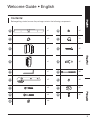
Contents:
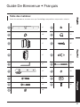
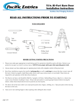
Before getting started, ensure the package contains the following components:
A
x1
E4
x4
B
x5
F
x1
C1
x1
F1
x2
C2
x1
F2
x2
C3
x1
G
x5
D
x2
G1
x5
E1
x4
H1
x2
E2
x4
H2
x2
E3
x8

4
Tools you will need
Electric drill
Tape measure
Screwdriver
Wrench and
socket set
Level
Router
Drill bit
7/64” (2.8 mm),
1/8” (3 mm),
1/4” (6.5 mm),
5/16” (8 mm),
7/16” (11 mm)
Marking tools
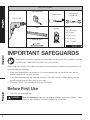
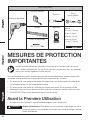
IMPORTANT SAFEGUARDS
Read these instructions carefully and retain them for future use. If this product is passed
to a third party, then these instructions must be included.
When using the product, basic safety precautions should always be followed to reduce the risk of
injury including the following:
• If your door opening has trim around it, it is recommended that you install the track onto a
header board above the door opening.
• If your door opening does not have trim around it, the track can be installed directly into the
drywall provided you find the studs in your walls.
• The track CANNOT be mounted directly into the drywall.
Before First Use
• Check for transport damage.
Risk of suffocation! Keep any packaging materials away from children – these
materials are a potential source of danger, e.g. suffocation.
DANGER

5
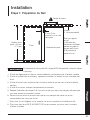
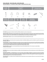
Installation
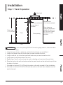
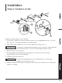
Step 1: Track Preparation
Door height +
1.75" (44 mm)
Keep level
Door opening
Floor
Door
2” (51 mm) minimum
on one side of
the door
Header board
(1 x 6 recommended)
Floor clearance:
Using the dimensions
shown will allow for a
3/8” (9.5 mm) space
between the door
and floor.
If your door opening DOES NOT have trim going around it, follow the below
steps.
1. Using the layout above as reference, position the track where you would like it.
2. Using a stud finder, locate the studs where you want to attach the track.
3. Using a small nail, tap it into the drywall and make sure you have located the stud.
4. Using a pencil, mark the location of the stud.
5. Repeat steps 2 and 3 until you have five marks indicating you have found five wall studs.
6. Place the track on the wall and make sure the five pencil marks on the wall match up with the
five holes in the track.
7. If the holes in the track DO ALIGN with the marks on the wall, proceed to Track Installation.
8. If the holes in the track DO NOT ALIGN with the marks on the wall, then a header board will
need to be used.
NOTICE

6
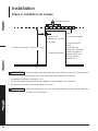
Installation
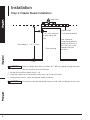
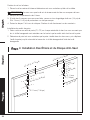
Step 2: Header Board Installation
Door height + 1.75” (44 mm)
Keep level
Door opening
Floor
2” (51 mm) minimum
on one side of the
door
Header board
(1 x 6 recommended)
Floor clearance:
Using the dimensions
shown will allow for a
3/8” (9.5 mm) space
between the door
and floor.
Draw a straight vertical line of at least 3.5” (89 mm), going through the mark
that you made for the stud location.
1. Locate and mark the center of the 1 x 6.
2. Using the center line of the header board, line it up to the stud marks.
3. Using interior screws, mount the header board to the wall.
Use a level to ensure the header board is level when installing it to the studs.
NOTICE
NOTICE

7
Installation
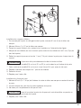
Step 3: Track Installation
C3
C1
A
B
G1
G
Attaching the track directly to the studs:
1. Using the 5 marks you made, drill a 1/4” (6 mm) pilot hole 1” - 3” (25 - 76 mm) deep on each
mark.
2. Slide the washer (G1) over the screw (G) and repeat for all 5 screws.
If the door is going to stop before the last hole (8” / 20 cm) on either end, then
the door stop C1 or C2 will need to be installed onto the rail first.
3. Position the track over the drilled holes.
4. Starting at one end of the track, insert the screw (G) through the track and then through the
spacer (B) and into the pilot hole.
5. Use a wrench to tighten the screw.
Do not tighten the screw completely until all screws are installed and the track
is level.
6. Repeat steps 4 and 5 for the remaining holes (checking with a level for each screw installed).
NOTICE
NOTICE

8
Attaching the track to the header board:
1. Place the track in the center of the header board and determine where you want it to be
installed.
Make sure the track is level before making your hole marks.
2. Mark locations for all 5 holes.
3. Using the 5 marks you made, drill a 1/4” (6 mm) pilot hole 1” - 3” (25 - 76 mm) deep on each
mark.
4. Follow steps 2 through 6 under “Attaching the track directly to the studs”.
Installing door stops
1. Slide one door stop (C1, C2) on each end of the tack, making sure the hex screws are facing
up and the actual stops are facing the door.
2. Determine where you want the door to stop in both directions, then move the door stop to that
location and tighten down the hex screws with the hex wrench.
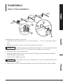
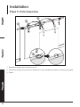
Step 4: Installing Hangers and Anti-Jump Disc
2 - 7/16” (62 mm)
2 - 7/16” (62 mm)
1 - 1/2” (38 mm)
1 - 1/2” (38 mm)
3 - 9/16” (90 mm)
3 - 9/16” (90 mm)
Ø7/16” (11 mm)
Ø7/16” (11 mm)
2” (51 mm)
2” (51 mm)
NOTICE

9
D
H1
E4
E3
E2
H2
/
E1
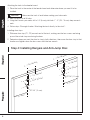
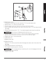
Installing hanger brackets
1. Starting from the left side of the door, measure in 2” (51 mm) and make a mark.
2. Measure down 1-1/2” (38 mm) and make a mark.
3. Take the hanger bracket and center the top hole over the line intersection.
4. Mark the bottom hole (making sure the center of the bottom hole is 2” (51 mm) away from the
door edge).
5. Remove the bracket and drill a 7/16” (11 mm) hole through the door for each bracket hole.
Door thickness will determine which bolt size to use.
6. Slide the washer (E3) over the screw (E1 or E2) and insert through the back of the door.
7. Slide the washer (E3) over the screw and screw on nut (E4), then hand-tighten.
8. Repeat steps 6 and 7 for the bottom hole.
9. Tighten down nuts.
10. Repeat for other side.
Installing anti-jump disk
1. Measure 2-7/16” (62 mm) from the inside of the hanger and make a mark in the center of the
door edge.
2. Screw the anti-jumper disc into the door top.
3. Do not tighten the anti-jumper disc all the way.
Prior to hanging the door, the anti-jump discs must be hanging over the front
edge of the door.
4. Repeat for other side.
NOTICE
NOTICE

10
Installation
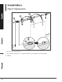
Step 5: Hanging Door
1
2
H1
A
D
D
1. Lift the door onto the track.
2. Turn the anti-jumper discs to where they are now centered on the door edge.
3. Tighten.

11
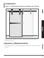
Installation
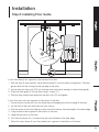
Step 6: Installing Floor Guide
1/4” (6 mm)
3/4” (19 mm)
F1
F
If your door already has a groove in the bottom of the door:
1. With the door at open position, place the floor guide (F) into the center of the groove. (The floor
guide should not be sticking outside the edge of the door.)
2. Loosen the back door stop (C2) and slide the door backwards (enough to see the floor guide).
3. Screw the floor guide (F) into the floor using 2 screws (F1).
4. Slide the door forward and reposition the door stop (C2) and tighten.
If your door does not have a groove in the bottom of the door:
1. Loosen the anti-jumper disc turn (to where they are hanging over the front edge of the door).
2. Lift the door off the track and place on a flat surface.
3. Find the center of the door edge and draw a line that reaches the entire length of the door edge.
4. Using a router, make a groove in the bottom of the door.
5. Hang the door back on the track.
6. Turn the anti-jumper discs to where they are now centered on the door edge.
7. Follow the steps above (If your door already has a groove in the bottom of the door).

12
Installation
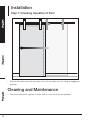
Step 7: Checking Operation of Door
• Slide the door back and forth and make sure it rolls smoothly and isn’t hitting or dragging on
anything.
Cleaning and Maintenance
• Check the components regularly to make sure all screws and bolts are tightened.

13
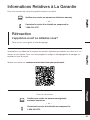
Warranty Information
To obtain a copy of the warranty for this product:
Visit amazon.com/AmazonBasics/Warranty
— or —
Contact Customer Service at 1-866-216-1072
Feedback
Love it? Hate it?
Let us know with a customer review.
AmazonBasics is committed to delivering customer-driven products that live up to your high
standards. We encourage you to write a review sharing your experiences with the product.
Please visit: amazon.com/review/review-your-purchases#
For further services:
Visit amazon.com/gp/help/customer/contact-us
— or —
Contact Customer Service at 1-866-216-1072

14
Guía de Bienvenida
•
Español
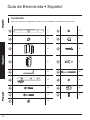
Contenido:
Antes de comenzar, asegúrese de que la caja contenga los siguientes componentes:
A
x1
E4
x4
B
x5
F
x1
C1
x1
F1
x2
C2
x1
F2
x2
C3
x1
G
x5
D
x2
G1
x5
E1
x4
H1
x2
E2
x4
H2
x2
E3
x8

15
Herramientas que necesitará
Taladro eléctrico
Cinta métrica
Destornillador
Llave y
juego de dados
Nivel Enrutador
Broca
2,8mm (7/64 pulgadas),
3 mm (1/8 pulgadas),
6,5 mm (1/4 pulgadas),
8 mm (5/16 pulgadas),
11mm (7/16 pulgadas)
Herramientas para marcar
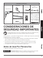
CONSIDERACIONES DE
SEGURIDAD IMPORTANTES
Lea atentamente estas instrucciones y guárdelas para usarlas más adelante. En caso
de entregar este producto a un tercero, también se debe incluir esta guía.
Al usar el producto, y para reducir el riesgo de lesiones, se deben seguir siempre las precauciones
de seguridad básicas, incluidas las siguientes:
• Si la abertura de la puerta tiene molduras alrededor, se recomienda que instale la corredera
sobre un tablero de cabecera por encima de la abertura de la puerta.
• Si la abertura de su puerta no tiene borde de marco, la corredera puede ser instalada
directamente en el panel de yeso siempre y cuando encuentre los pernos en su pared.
• La corredera NO PUEDE montarse directamente al panel de yeso.
Antes de Usar Por Primera Vez
• Revise por si hay daños ocurridos en el transporte.
¡Riesgo de asfixia! Mantenga los materiales de empaque lejos de los niños,
ya que estos materiales son una posible fuente de peligro (asfixia).
PELIGRO

16
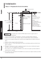
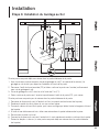
Instalación
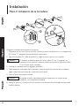
Paso 1: Preparación de la Corredera
Altura de la puerta
+ 44mm
(1,75 pulgadas)
Conserve el nivel
Apertura de la puerta
Piso
Puerta
51mm (2 pulgadas)
mínimo en un lado
de la puerta
Tablero de
la cabecera
(1 x 6 recomendado)
Libramiento desde
el piso:
Las dimensiones
mostradas le permitirán
un espacio de
libramiento entre la
puerta y el piso de
9,5mm (3/8 pulgadas).
Si la puerta que se abre NO TIENE bodes de marco, siga los pasos a
continuación.
1. Usando el diseño anterior como referencia, coloque la corredera donde usted guste.
2. Usando un buscador de vigas, ubique los pernos en donde desea colocar la corredera.
3. Usando una uña pequeña, golpee en el panel de yeso asegurándose de haber localizado el
perno.
4. Usando un lápiz, marque la ubicación del perno.
5. Repita los pasos 2 y 3 hasta que tenga cinco marcas que indiquen que ha encontrado cinco
pernos de pared.
6. Coloque la corredera en la pared y asegúrese de que las cinco marcas de lápiz en la pared
coincidan con los cinco agujeros en la corredera.
7. Si los orificios en la corredera SE ALINEAN con las marcas en la pared, proceda a realizar la
instalación de la corredera.
8. Si los orificios en la corredera NO SE ALINEAN con las marcas en la pared, tendrá que instalar
un tablero de cabecera.
AVISO

17
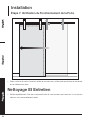
Instalación
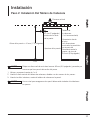
Paso 2: Instalación Del Tablero de Cabecera
Altura de la puerta + 44mm (1,75 pulgadas)
Conserve el nivel
Apertura de la puerta
Piso
51mm (2 pulgadas)
mínimo en un lado
de la puerta
Tablero de
la cabecera
(1 x 6 recomendado)
Libramiento desde
el piso:
Las dimensiones
mostradas le permitirán
un espacio de
libramiento entre la
puerta y el piso de
9,5mm (3/8 pulgadas).
Dibuje una línea vertical recta de al menos 89 mm (3,5 pulgadas), pasando por
la marca que hizo para la ubicación del perno.
1. Ubique y marque el centro de 1 x 6.
2. Usando la línea central del tablero de cabecera, alinéelo con las marcas de los pernos.
3. Usando tornillos interiores, monte el tablero de cabecera a la pared.
Use un nivel para asegurarse de que el tablero esté nivelado al instalarlo en
los pernos.
AVISO
AVISO

18
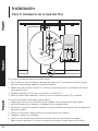
Instalación
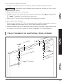
Paso 3: Instalación de la Corredera
C3
C1
A
B
G1
G
Coloque la corredera directamente a los pernos:
1. Guiándose por las cinco marcas que hizo, perfore un orificio inicial de 6mm (1/4 pulgadas) de
25-76mm (1-3 pulgadas) de profundidad en cada marca.
2. Deslice la arandela (G1) sobre el tornillo (G) y haga lo mismo para los cinco tornillos.
Si la puerta se detendrá antes del último orificio (20cm / 8 pulgadas) en
cualquiera de los extremos, entonces tendrá que instalar el tope de la puerta
C1 o C2 antes que la corredera.
3. Coloque la corredera sobre los agujeros taladrados.
4. Comenzando en un extremo de la corredera, inserte el tornillo (G) a través de la corredera y
luego a través del espaciador (B) y dentro del orificio inicial.
5. Use una llave para apretar el tornillo.
No apriete el tornillo completamente hasta que todos los tornillos estén
instalados y la corredera esté nivelada.
6. Repita los pasos 4 y 5 para los orificios restantes (use un nivel de burbuja para verificar cada
tornillo instalado).
AVISO
AVISO

19
Una la corredera al tablero de cabecera:
1. Coloque la corredera en el centro del tablero y determine dónde desea que se instale.
Asegúrate de que la corredera esté nivelada antes de hacer las marcas de los
agujeros.
2. Marque ubicaciones para los cinco hoyos.
3. Guiándose por las cinco marcas que hizo, perfore un orificio inicial de 6
1/4 pulgadas) de
25-76 1-3 pulgadas) de profundidad en cada marca.
4. Siga los pasos 2 a 6 en "Colocar la corredera directamente en los pernos".
Instalación de los topes de puerta
1. Deslice un tope de puerta (C1, C2) en cada extremo de la corredera, asegurándose de que los
tornillos hexagonales estén hacia arriba y que los topes vean hacia la puerta.
2. Determine dónde desea que se detenga la puerta en ambas direcciones, luego mueva el tope
de la puerta a esa ubicación y apriete los tornillos hexagonales con la llave hexagonal.
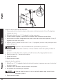
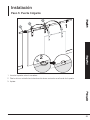
Paso 4: Instalación de Las Perchas y Disco Antisalto
62
2 - 7/16 pulgadas)
62
2 - 7/16 pulgadas)
38 mm (1 - 1/2 pulgadas)
38 mm (1 - 1/2
pulgadas)
90 mm (3 - 9/16 pulgadas)
90 mm (3 - 9/16
pulgadas)
Ø 11 7/16 pulgadas)
Ø 11
(7/16 pulgadas)
51 mm (2 pulgadas)
51 mm
(2 pulgadas)
AVISO

20
D
H1
E4
E3
E2
H2
/
E1
Instalación de los soportes de suspensión
1. Comenzando desde el lado izquierdo de la puerta, mida hacia adentro 51 mm (2 pulgadas) y
coloque una marca.
2. Mida hacia abajo 38 mm (1-1/2 pulgadas) y colque una marca.
3. Tome el soporte colgante y centre el orificio superior sobre la intersección de la línea.
4. Marque el orificio inferior (asegurándose de que el centro del orificio inferior quede a 51 mm (2
pulgadas) del borde de la puerta).
5. Retire el soporte y perfore un orificio de 11 mm (7/16 pulgadas) a través de la puerta para cada
orificio del soporte.
El grosor de la puerta determinará qué tamaño de perno usar.
6. Deslice la arandela (E3) sobre el tornillo (E1 o E2) e insértelo a través de la parte posterior de
la puerta.
7. Deslice la arandela (E3) sobre el tornillo y atornille la tuerca (E4), luego apriétela a mano.
8. Repita los pasos 6 y 7 para el orificio inferior.
9. Aprieta las tuercas.
10. Repita para el otro lado.
Instalación de disco antisalto
1. Mida 62 mm (2-7/16 pulgadas) desde el interior del soporte y haga una marca en el centro del
borde de la puerta.
2. Atornille el disco antisalto en la parte superior de la puerta.
3. No apriete el disco antisalto por completo.
Antes de colgar la puerta, los discos antisalto deben colgar sobre el borde
frontal de la puerta.
4. Repita para el otro lado.
AVISO
AVISO
La page est en cours de chargement...
La page est en cours de chargement...
La page est en cours de chargement...
La page est en cours de chargement...
La page est en cours de chargement...
La page est en cours de chargement...
La page est en cours de chargement...
La page est en cours de chargement...
La page est en cours de chargement...
La page est en cours de chargement...
La page est en cours de chargement...
La page est en cours de chargement...
La page est en cours de chargement...
La page est en cours de chargement...
La page est en cours de chargement...
La page est en cours de chargement...
-
 1
1
-
 2
2
-
 3
3
-
 4
4
-
 5
5
-
 6
6
-
 7
7
-
 8
8
-
 9
9
-
 10
10
-
 11
11
-
 12
12
-
 13
13
-
 14
14
-
 15
15
-
 16
16
-
 17
17
-
 18
18
-
 19
19
-
 20
20
-
 21
21
-
 22
22
-
 23
23
-
 24
24
-
 25
25
-
 26
26
-
 27
27
-
 28
28
-
 29
29
-
 30
30
-
 31
31
-
 32
32
-
 33
33
-
 34
34
-
 35
35
-
 36
36


Amazon Basics AB-DH553-FB Manuel utilisateur
- Taper
- Manuel utilisateur
dans d''autres langues
Documents connexes
Autres documents
-
 Pacific Entries BPFLM2255-4880-15 Mode d'emploi
-
 Pacific Entries BPP3220-7284-15 Mode d'emploi
-
 AmazonBasics B07GF54KV8 Manuel utilisateur
-
 TRUporte BD054W01IA1TGG36084 Manuel utilisateur
-
 TRUporte NL60-W9-ES1-36 Mode d'emploi
-
Johnson Hardware 2060 SERIES Manuel utilisateur
-
Kohler K-2495-F41 Guide d'installation
-
-
-
ReliaBilt BD054W01IA1TGG36084 Manuel utilisateur


