Samsung SMH1611W/XAC Guide d'installation
- Catégorie
- Fours
- Taper
- Guide d'installation

INSTALLATION INSTRUCTIONS
OVER THE RANGE MICROWAVE OVEN
BEFORE YOU BEGIN (Read these instructions completely and carefully.)
IMPORTANT
Save these instructions for local inspector’s use.
IMPORTANT
Observe all governing codes and ordinances.
• Note to Installer - Be sure to leav
e these instructions with the Consumer.
• Note to Consumer - Keep these instr
uctions for future reference.
• Skill level - Installation of this appliance requires basic mechanical and electr
ical skills.
• Proper installation is the responsibility of the installer.
• Product failure due to improper installation is not covered under the Warranty.
READ CAREFULLY. KEEP THESE INSTRUCTIONS.
DE68-03587B-EN.indd 1 2008-12-09 �� 4:13:00

Placement Of The Mounting Plate . . . . . 8
Removing the Mounting Plate . . . . . . . . .8
Finding the Wall Studs . . . . . . . . . . . . . . .8
Determining Wall Plate Location . . . . . . .9
Aligning the Wall Plate . . . . . . . . . . . . . . .10
Installation Types . . . . . . . . . . . . . . . . . . 11
A
. Outside Top Exhaust . . . . . . . . . . . . . . . .12
Attach Mounting Plate to the Wall . . . . . .12
Preparation of Top Cabinet . . . . . . . . . . .12
Installation Procedure For Exhaust Adaptor
And Proper Damper Operation Check . . .13
Mount the Microwave Oven . . . . . . . . . . .13
Adjust the Exhaust Adaptor . . . . . . . . . . .14
Connecting Ductwork . . . . . . . . . . . . . . . .14
B. Recirculating . . . . . . . . . . . . . . . . . . . . . .15
Attach Mounting Plate to Wall . . . . . . . . .15
Preparation of Top Cabinet . . . . . . . . . . .15
Adapting Microwave Blower For
Recirculation . . . . . . . . . . . . . . . . . . . . . .16
Mount the Microwave Oven . . . . . . . . . . .17
Install the Charcoal Filter . . . . . . . . . . . . .18
C. Outside Back Exhaust . . . . . . . . . . . . . . .19
Preparing Rear Wall for
Outside Back Exhaust . . . . . . . . . . . . . . .19
Attach Mounting Plate to Wall . . . . . . . . .20
Preparation of Top Cabinet . . . . . . . . . . .20
Adapting Microwave Blower For Outside
Back Exhaust . . . . . . . . . . . . . . . . . . . . . .20
Mount the Microwave Oven . . . . . . . . . . .22
Before You Use Your Microwave . . . . . . . 23
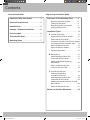
Step-by-step installation guide
Contents
2
Important Safety Instructions . . . . . . . . 3
Electrical Requirements . . . . . . . . . . . . . 3
Hood Exhaust . . . . . . . . . . . . . . . . . . . . . 4
Damage - Shipment/installation . . . . . . . 6
Parts Included . . . . . . . . . . . . . . . . . . . . . 6
Tools You Will Need . . . . . . . . . . . . . . . . . 7
Mounting Space . . . . . . . . . . . . . . . . . . . 7
General information
DE68-03587B-EN.indd 2 2008-12-09 �� 4:13:00

3
General information
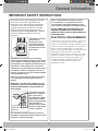
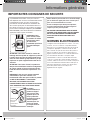
IMPORTANT SAFETY INSTRUCTIONS
This product requires a three-prong grounded outlet.
The installer must perform a ground continuity
check on the power outlet box before beginning the
installation to insure that the outlet box is properly
grounded. If not properly grounded, or if the outlet
box does not meet electrical requirements noted
(under ELECTRICAL REQUIREMENTS), a qualified
electrician should be employed to correct any
deficiencies.
)NSUREPROPER
GROUNDEXISTS
BEFOREUSE
CAUTION: For personal
safety, remove
house fuse or open
circuit breaker before
beginning installation
to avoid severe or fatal
shock injury.
CAUTION: For personal safety, the mounting
surface must be capable of supporting the cabinet
load, in addition to the added weight of this 63–85
pound product, plus additional oven loads of up to
50 pounds or a total weight of 113–135 pounds.
CAUTION: For personal safety, this product cannot
be installed in cabinet arrangements such as an
island or a peninsula. It must be mounted to BOTH
a top cabinet AND a wall.
NOTE: For easier installation and personal safety,
it is recommended that two people install this
product.
IMPORTANT – PLEASE READ CAREFULLY. FOR
PERSONAL SAFETY, THIS APPLIANCE MUST BE
PROPERLY GROUNDED TO AVOID SEVERE OR
FATAL SHOCK.
)NSUREPROPER
GROUNDEXISTS
BEFOREUSE
The power cord of this
appliance is equipped
with a three-prong
(grounding) plug which
mates with a standard
three-prong (grounding)
wall receptacle to
minimize the possibility
of electric shock hazard
from this appliance.
You should have the wall receptacle and circuit
checked by a qualified electrician to make sure the
receptacle is properly grounded.
DE68-03587B-EN.indd 3 2008-12-09 �� 4:13:01
Where a standard two-prong wall receptacle
is encountered, it is very important to have it
replaced with a properly grounded three-prong
wall receptacle, installed by a qualified electrician.
DO NOT
, UNDER ANY CIRCUMSTANCES, CUT,
DEFORM OR REMOVE ANY OF THE PRONGS
FROM THE POWER CORD. DO NOT USE WITH AN
EXTENSION CORD.
ELECTRICAL REQUIREMENTS
Product rating is 120 volts AC, 60 Hertz, 13 amps and
1.5 kilowatts. This product must be connected to a
supply circuit of the proper voltage and frequency. Wire
size must conform to the requirements of the National
Electrical Code or the prevailing local code for this
kilowatt rating. The power supply cord and plug should
be brought to a separate branch circuit single
grounded outlet of at least 15 A and max of 20 A. The
outlet box should be located in the cabinet above the
microwave oven. The outlet box and supply circuit
should be installed by a qualified electrician and
conform to the National Electrical Code or the
prevailing local code.

4
General information
HOOD EXHAUST
NOTE: Read these next two pages only if you plan to vent your exhaust to the outside.
If you plan to recirculate the air back into the room, proceed to page 11.
OUTSIDE TOP EXHAUST (EXAMPLE ONLY)
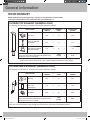
The following chart describes an example of one possible ductwork installation.
DUCT PIECES
EQUIVALENT
LENGTH
x
NUMBER
USED
=
EQUIVALENT
LENGTH
Roof Cap 24 ft. x (1) = 24 ft.
12 Ft. Straight Duct
(6” Round)
12 ft. x (1) = 12 ft.
Rectangular-to-Round
Transition Adaptor*
5 ft. x (1) = 5 ft.
Equivalent lengths of duct pieces are based on
actual tests and reflect requirements for good venting
performance with any vent hood.
Total
Length
= 41 ft.
* IMPOR
TANT: If a rectangular-to-round transition adaptor is used, the bottom corners of the damper
will have to be cut to fit, using the tin snips, in order to allow free movement of the damper.
OUTSIDE BACK EXHAUST (EXAMPLE ONLY)
The following chart describes an example of one possible ductwork installation.
DUCT PIECES
EQUIVALENT
LENGTH
x
NUMBER
USED
=
EQUIVALENT
LENGTH
Wall Cap 40 ft. x (1) = 40 ft.
3 Ft. Straight Duct
(3¼” x 10”
Rectangular)
3 ft. x (1) = 3 ft.
90° Elbow 10 ft. x (2) = 20 ft.
Equivalent lengths of duct pieces are based on
actual tests and reflect requirements for good venting
performance with any vent hood.
Total
Length
= 63 ft.
NOTE: For back exhaust, care should be taken to align exhaust with space between studs, or wall should be prepared
at the time it is constructed by leaving enough space between the wall studs to accommodate exhaust.
DE68-03587B-EN.indd 4 2008-12-09 �� 4:13:01

5
General information
NOTE: If you need to install ducts, note that the total duct
length of 3¼” x 10” rectangular or 6” diameter round duct
should not exceed 140 equivalent feet.
Outside ventilation requires a HOOD EXHAUST DUCT.
Read the following carefully.
NOTE: It is important that venting be installed using the
most direct route and with as few elbows as possible.
This ensures clear venting of exhaust and helps prevent
blockages. Also, make sure dampers swing freely and
nothing is blocking the ducts.
Exhaust connection:
The hood exhaust has been designed to mate with a
standard 3¼” x 10” rectangular duct.
If a round duct is required, a rectangular-to-round
transition adaptor must be used. Do not use less than a
6” diameter duct.
Maximum duct length:
For satisfactory air movement, the total duct length of 3¼”
x 10” rectangular or 6” diameter round duct should not
exceed 140 equivalent feet.
Elbows, transitions, wall and roof caps, etc.,
present additional resistance to airflow and are equivalent
to a section of straight duct which is longer than their
actual physical size. When calculating the total duct
length, add the equivalent lengths of all transitions and
adaptors plus the length of all straight duct sections. The
chart below shows you how to calculate total equivalent
ductwork length using the approximate feet of equivalent
length of some typical ducts.
DUCT PIECES
EQUIVALENT
LENGTH
x NUMBER USED =
EQUIVALENT
LENGTH
Rectangular-to-Round
Transition Adaptor*
5 ft. x ( ) = ft.
Wall Cap 40 ft. x ( ) = ft.
90° Elbow 10 ft. x ( ) = ft.
45° Elbow 5 ft. x ( ) = ft.
90° Elbow 25 ft. x ( ) = ft.
45° Elbow 5 ft. x ( ) = ft.
Roof Cap 24 ft. x ( ) = ft.
Straight Duct 6” Round or
3¼” x 10” Rectangular
1 ft. x ( ) = ft.
Total Ductwork = ft.
* IMPORTANT: If a rectangular-to-round transition
adaptor is used, the bottom corners of the damper
will have to be cut to fit, using the tin snips, in
order to allow free movement of the damper.
Equivalent lengths of duct pieces
are based on actual tests and reflect
requirements for good venting performance
with any vent hood.
DE68-03587B-EN.indd 5 2008-12-09 �� 4:13:01

6
General information
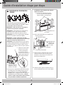
• If the unit is damaged in shipment, return the unit to the store in which it was bought for repair or replacement.
• If the unit is damaged by the customer, repair or replacement is the responsibility of the customer.
• If the unit is damag
ed by the installer (if other than the customer), repair or replacement must be made by
arrangement between customer and installer.
DAMAGE - SHIPMENT/INSTALLATION
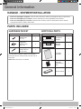
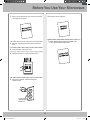
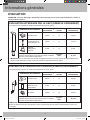
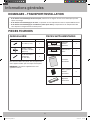
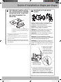
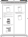
HARDWARE PACKET
PART QUANTITY
Template
INSTALLATION
INSTRUCTIONS
Wood Screws
(¼” x 2”)
1
Template
INSTALLATION
INSTRUCTIONS
Toggle Bolts
(and wing nuts)
(3/16” x 3”)
2
Template
INSTALLATION
INSTRUCTIONS
Self-aligning
Machine Screws
(¼”-28 x 3¼”)
2
Template
INSTALLATION
INSTRUCTIONS
You will find the installation hardware contained in a
packet with the unit. Check to make sure you have all
these parts.
NOTE: Some extra parts are included.
ADDITIONAL PARTS
PART QUANTITY
4/0#!").%44%-0,!4%
2%!27!,,4%-0,!4%
Top Cabinet
Template
1
4/0#!").%44%-0,!4%
2%!27!,,4%-0,!4%
Rear Wall
Template
1
Template
INSTALLATION
INSTRUCTIONS
Installation
Instructions
1
Template
INSTALLATION
INSTRUCTIONS
Separately
Packed Grease
Filter
2
Template
INSTALLATION
INSTRUCTIONS
Exhaust adaptor 1
PARTS INCLUDED
DE68-03587B-EN.indd 6 2008-12-09 �� 4:13:02

7
General information
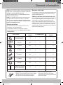
# 1 and #2
Phillips screwdriver
Pencil Ruler or tape measure and
straight edge
Carpenter square (optional)
Tin snips (for cutting
damper, if required)
Scissors (to cut template, if
necessary)
Electric drill with
3
/16”, ½” and
5
/8” drill bits
Filler blocks or scrap wood
pieces, if needed for top
cabinet spacing (used on
recessed bottom cabinet
installations only)
Gloves Saw
(saber, hole or keyhole)
Stud finder or Hammer
(optional)
Safety goggles
Level Duct and masking tape
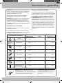
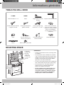
TOOLS YOU WILL NEED
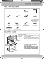
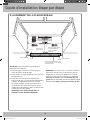
16½”
30”
2”
30”min
Bottom edge of
cabinet needs
to be 30” or
more from
the cooking
surface
Backsplash
66” or More
from the Floor
to the Top of
the Microwave
NOTES:
•
The space betw
een the cabinets must be 30” wide
and free of obstructions.
• If the space betw
een the cabinets is greater than
30”, a Filler Panel Kit may be used to fill in the gap
between the microwave oven and the cabinets.
Your Owner’s Manual contains the kit number for
your model.
• This micro
wave oven is for installation over ranges
up to 36” wide.
• If y
ou are going to vent your microwave oven
to the outside, see Hood Exhaust Section for
exhaust duct preparation.
• When installing the micr
owave oven beneath
smooth, flat cabinets, be careful to follow the
instructions on the top cabinet template for
power cord clearance.
MOUNTING SPACE
DE68-03587B-EN.indd 7 2008-12-09 �� 4:13:04

8
Step-by-step installation guide
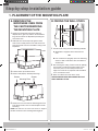
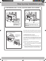
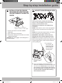
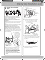
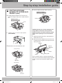
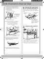
1. PLACEMENT OF THE MOUNTING PLATE
A. REMOVING THE
MICROWAVE OVEN FROM
THE CARTON/REMOVING
THE MOUNTING PLATE
1. Remove the installation instructions, Exhaust
adaptor, filters, glass tray and the small hardware
bag. Do not remove the Styrofoam protecting the
front of the oven.
2. Fold back all 4 carton flaps fully against carton
sides. Then carefully roll the oven and carton over
onto the top side. The oven should be resting in the
Styrofoam.
3TYROFOAM
#ARTON
3. Pull the carton up and off the oven.
4. Remove and properly discard plastic bags.
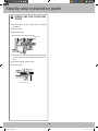
Screws
Screws
Mounting Plate
5. Remove the 2 screws from the mounting plate. This
plate will be used as the rear wall template and for
mounting.
NOTE: You will have to reuse two screws in original
location of outcase after removing mounting plate.
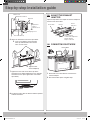
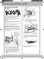
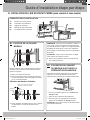
B. FINDING THE WALL STUDS
7ALL3TUDS
#ENTER
1. Find the studs, using one of the following methods:
A. Stud finder-a magnetic device which locates
nails.
OR
B. Use a hammer to tap lightly across the mounting
surface to find a solid sound. This will indicate a
stud location.
2. After locating the stud(s), find the center by probing
the wall with a small nail to find the edges of the
stud. Then place a mark halfway between the
edges. The center of any adjacent studs should be
16” or 24” from this mark.
3. Draw a line down the center of the studs.
THE MICROWAVE MUST BE CONNECTED TO AT
LEAST ONE WALL STUD.
DE68-03587B-EN.indd 8 2008-12-09 �� 4:13:05

9
Step-by-step installation guide
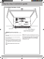
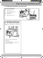
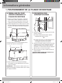
C. DETERMINING WALL PLATE LOCATION UNDER YOUR CABINET
C
L
16-1/2"
Plate position – beneath flat bottom cabinet
A
t
l
e
a
s
t
3
0
q
Draw a vertical line on
the wall at the center of
the 30
q wide space.
Tape the Rear Wall
Template onto the wall
matching the centerline
and touching the
bottom of the cabinet.
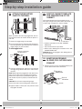
C
L
Plate position – beneath framed recessed
cabinet bottom
30q to Cooktop
Draw a vertical line on the wall at the center of the
30
q space.
Tape the Rear Wall Template onto the wall
matching the centerline and touching the bottom
cabinet frame.
C
L
Plate position – beneath recessed bottom
cabinet with front overhang
Draw a line on the
back wall equal to the
depth of the front
overhang.
30" to Cooktop
Your cabinets may have decorative trim that interferes
with the microwave installation. Remove the decorative
trim to install the microwave properly and to make it level.
THE MICROWAVE MUST BE LEVEL.
Use a level to make sure the cabinet bottom is level.
If the cabinets have a front overhang only, with no back
or side frame, install the mounting plate down the same
distance as the front overhang depth. This will keep the
microwave level.
1
. Measure the inside depth of the front overhang.
2
. Draw a horizontal line on the back wall an equal
distance below the cabinet bottom as the inside depth
of the front overhang.
3
. For this type of installation with front overhang only,
align the mounting tabs with this horizontal line, not
touching the cabinet bottom as described in Step D.
DE68-03587B-EN.indd 9 2008-12-09 �� 4:13:08

10
Step-by-step installation guide
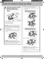
D. ALIGNING THE WALL PLATE
C
L
CAUTION: Wear gloves to avoid cutting
fingers on sharp edges.
Area E
Hole B
Hole A
Centerline
notches
Draw a Vertical Line
on Wall from Center
of Top Cabinet
Draw a Horizontal line on wall from
bottom of “Rear Wall Template”.
Horizontal Line
Horizontal Line
CAUTION: Wear gloves to avoid cutting fingers on sharp
edges.
1. Draw a Vertical line on the wall at the center of the 30"
wide space.
2. Draw a Horizontal line on the wall at the bottom of
“Rear Wall Template”.
3. Drill 5/8" holes for toggle bolts on 3 locations (Hole A,
Hole B, Hole C) but if the location of hole is same as
that of stud, drill a 3/16" hole for wood screw. In other
words, toggle bolt can not be used to the location of
stud.
NOTE: DO NOT MOUNT THE PLATE AT THIS
TIME.
NOTE: Holes A, B and C are inside area E. If none of A,
B and C is in a stud, find a stud somewhere in area E and
draw a forth circle to line up with the stud. It is important
to use at least one wood screw mounted firmly in a
stud to support the weight of the microwave. Set the
mounting plate aside.
DE68-03587B-EN.indd 10 2008-12-09 �� 4:13:09

11
Step-by-step installation guide
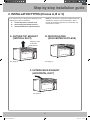
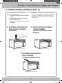
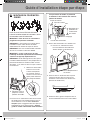
2. INSTALLATION TYPES (Choose A, B or C)
This microwave oven is designed for adaptation to the
following three types of ventilation:
A. Outside Top Exhaust (Vertical Duct)
B. Recirculating (Non-Vented Ductless)
C. Outside Back Exhaust (Horizontal Duct)
NOTE: This microwave is shipped assembled for Outside
Top Exhaust (except for non-vented models). Select
the type of ventilation required for your installation and
proceed to that section.
A. OUTSIDE TOP EXHAUST
(VERTICAL DUCT)
B. RECIRCULATING
(NON-VENTED DUCTLESS)
!DAPTORIN0LACE
FOR/UTSIDE
4OP%XHAUST
See page 12 See page 15
C. OUTSIDE BACK EXHAUST
(HORIZONTAL DUCT)
See page 19
DE68-03587B-EN.indd 11 2008-12-09 �� 4:13:09

12
Step-by-step installation guide
A. OUTSIDE TOP EXHAUST (Vertical Duct)
INSTALLATION OVERVIEW
A
1. Attach Mounting Plate to Wall
A2. Prepare Top Cabinet
A3. Mount the Microwave Oven
A4. Adjust the Exhaust Adaptor
A5. Connecting Ductwork
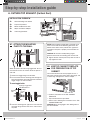
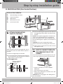
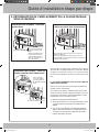
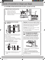
A1. ATTACH THE MOUNTING
PLATE TO THE WALL
Attach the plate to the wall using toggle bolts. At least
one wood screw must be used to attach the plate to a
wall stud.
1. Remove the toggle wings from the bolts.
2. Insert the bolts into the mounting plate through the
holes designated to go into drywall and reattach the
toggle wings to ¾” onto each bolt.
To use toggle bolts:
Wall
Toggle Wings
Toggle
Bolt
Bolt End
Spacing for Toggles More
Than Wall Thickness
Mounting
Plate
3. Place the mounting plate against the wall and insert
the toggle wings into the holes in the wall to mount
the plate.
NOTE: Before tightening toggle bolts and wood screw,
make sure the tabs on the mounting plate touch the
bottom of the cabinet when pushed flush against the
wall and that the plate is properly centered under the
cabinet.
CAUTION: Be careful to avoid pinching fingers
between the back of the mounting plate and the wall.
4. Tighten all bolts. Pull the plate away from the wall to
help tighten the bolts.
A2. USE TOP CABINET TEMPLATE
FOR PREPARATION OF TOP
CABINET
You need to drill holes for the top support screws, a
hole large enough for the power cord to fit through, and
a cutout large enough for the exhaust adaptor.
• Read the instructions on the TOP CABINET
TEMPLATE.
• Tape it underneath the top cabinet.
• Drill the holes, following the instructions on the TOP
CABINET TEMPLATE.
CAUTION: Wear safety goggles when drilling holes in
the cabinet bottom.
DE68-03587B-EN.indd 12 2008-12-09 �� 4:13:10

13
Step-by-step installation guide
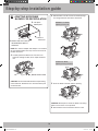
A4. MOUNT THE MICROWAVE OVEN
FOR EASIER INSTALLATION AND PERSONAL
SAFETY, WE RECOMMEND THAT TWO PEOPLE
INSTALL THIS MICROWAVE OVEN.
IMPORTANT: Do not grip or use handle during
installation.
NOTE: If your cabinet is metal, use the nylon grommet
around the power cord hole to prevent cutting of the
cord.
NOTE: We recommend using filler blocks if the cabinet
front hangs below the cabinet bottom shelf.
IMPORTANT: If filler blocks are not used, case
damage may occur from over tightening screws.
NOTE: When mounting the microwave oven, thread
power cord through hole in bottom of top cabinet. Keep
it tight throughout Steps 1-3. Do not pinch cord or lift
oven by pulling cord.
1. Lift microwave,
tilt it forward, and
hook slots at back
bottom edge onto
four lower tabs of
mounting plate.
2. Rotate front of oven
up against cabinet
bottom
3. Insert a self-aligning screw through top center
cabinet hole. Temporarily secure the oven by turning
the screw at least two full turns after the threads
have engaged. (It will be completely tightened later.)
Be sure to keep power cord tight. Be careful not
to pinch the cord, especially when mounting
flush to bottom of cabinet.
A3. INSTALLATION PROCEDURE
FOR EXHAUST ADAPTOR AND
PROPER DAMPER OPERATION
CHECK
• Read the instructions on the TOP CABINET
TEMPLATE.
• Tape it underneath the top cabinet.
• Drill the holes, following the instructions on the TOP
CABINET TEMPLATE.
CAUTION: Wear safety goggles when drilling holes in
the cabinet bottom.
DE68-03587B-EN.indd 13 2008-12-09 �� 4:13:11
ExhaustAdaptorandDamperis
shipped assembled to the filler-upper.

14
Step-by-step installation guide
A5. ADJUST THE EXHAUST
ADAPTOR
Open the top cabinet and adjust the exhaust adaptor to
connect to the house duct.
"ACKOF
-ICROWAVE
"LOWER0LATE
$AMPER
&OR&RONTTO"ACK
OR3IDETO3IDE!DJUSTMENT
3LIDETHE%XHAUST
!DAPTORAS.EEDED
A6. CONNECTING DUCTWORK
(OUSE$UCT
1. Extend the house duct down to connect to the
exhaust adaptor.
2. Seal exhaust duct joints using duct tape.
#ABINET&RONT
&ILLER"LOCK
-ICROWAVE/VEN4OP
3ELF!LIGNING3CREW
%QUIVALENTTO
$EPTHOF
#ABINET2ECESS
#ABINET"OTTOM3HELF
4. Attach the microwave oven to the top cabinet.
5. Insert 2 self-aligning screws through
outer top cabinet holes. Turn two full
turns on each screw.
6. Tighten center
screw completely.
7. Tighten the outer two screws to the top of the
microwave oven. (While tightening screws, hold the
microwave oven in place against the wall and the
top cabinet.)
8. Install grease filter. See the Owner’s Manual packed
with the microwave.
DE68-03587B-EN.indd 14 2008-12-09 �� 4:13:12

15
Step-by-step installation guide
B2. USE TOP CABINET TEMPLATE
FOR PREPARATION OF TOP
CABINET
You need to drill holes for the top support screws and
a hole large enough for the power cord to fit through.
• Read the instructions on the TOP CABINET
TEMPLATE.
• Tape it underneath the top cabinet.
• Drill the holes, following the instructions on the TOP
CABINET TEMPLATE.
CAUTION: Wear safety goggles when drilling holes in
the cabinet bottom.
B. RECIRCULATING (Non-Vented Ductless)
INSTALLATION OVERVIEW
B
1. Attach Mounting Plate to Wall
B2. Prepare Top Cabinet
B3. Adjust Blower
B4. Mount Microwave Oven
B5. Install Charcoal Filter
B1. ATTACH THE MOUNTING
PLATE TO THE WALL
Attach the plate to the wall using toggle bolts. At least
one wood screw must be used to attach the plate to a
wall stud.
1. Remove the toggle wings from the bolts.
2. Insert the bolts into the mounting plate through the
holes designated to go into drywall and reattach the
toggle wings to ¾” onto each bolt.
To use toggle bolts:
Wall
Toggle Wings
Toggle
Bolt
Bolt End
Spacing for Toggles More
Than Wall Thickness
Mounting
Plate
3. Place the mounting plate against the wall and insert
the toggle wings into the holes in the wall to mount
the plate.
NOTE: Before tightening toggle bolts and wood screw,
make sure to coincide bottom line of the Mounting
plate with Horizontal line of “Rear wall Template” and
then the Mounting plate is properly centered under the
cabinet.
CAUTION: Be careful to avoid pinching fingers
between the back of the mounting plate and the wall.
4. Tighten all bolts. Pull the plate away from the wall to
help tighten the bolts.
DE68-03587B-EN.indd 15 2008-12-09 �� 4:13:13

16
Step-by-step installation guide
B3. ADAPTING MICROWAVE
BLOWER FOR RECIRCULATION
Back of
Microwave
1. Remove and save screw
that holds blower plate to
microwave.
2. Lift up the
blower plate.
NOTE: The exhaust adaptor with damper is not needed
for recirculating models. You may want to save them for
possible future use.
3. Carefully pull out the blower unit. The wires will
extend far enough to allow you to adjust the blower
unit.
CAUTION: Do not touch blade of blower forpreventing
crack and break. Hold outer case when the blower pull
out or back into.
4. Roll the blower unit 90° so that fan blade openings
are facing toward the front of the microwave.
BEFORE: Fan Blade
Openings Facing UP
AFTER: Fan Blade
Openings Facing Forward
5. Place the blower unit back into the opening.
CAUTION: Do not pull or stretch the blower unit wiring.
Make sure the wires are not pinched.
6. Secure blower unit to microwave with the screw.
blower mortor screw
DE68-03587B-EN.indd 16 2008-12-09 �� 4:13:14

17
Step-by-step installation guide
B4. MOUNT THE MICROWAVE
OVEN
FOR EASIER INSTALLATION AND PERSONAL
SAFETY, WE RECOMMEND THAT TWO PEOPLE
INSTALL THIS MICROWAVE OVEN.
IMPORTANT: Do not grip or use handle during
installation.
NOTE: If your cabinet is metal, use the nylon grommet
around the power cord hole to prevent cutting of the
cord.
NOTE: We recommend using filler blocks if the cabinet
front hangs below the cabinet bottom shelf.
IMPORTANT: If filler blocks are not used, case
damage may occur from over tightening screws.
NOTE: When mounting the microwave oven, thread
power cord through hole in bottom of top cabinet. Keep
it tight throughout Steps 1-3. Do not pinch cord or lift
oven by pulling cord.
1. Lift microwave,
tilt it forward, and
hook slots at back
bottom edge onto
four lower tabs of
mounting plate.
2. Rotate front of oven
up against cabinet
bottom
3. Insert a self-aligning screw through top center
cabinet hole. Temporarily secure the oven by
turning the screw at least two full turns after
the threads have engaged. (It will be completely
tightened later.) Be sure to keep power cord
tight. Be careful not to pinch the cord,
especially when mounting flush to bottom of
cabinet.
#ABINET&RONT
&ILLER"LOCK
-ICROWAVE/VEN4OP
3ELF!LIGNING3CREW
%QUIVALENTTO
$EPTHOF
#ABINET2ECESS
#ABINET"OTTOM3HELF
4. Attach the microwave oven to the top cabinet.
5. Insert 2 self-aligning screws through
outer top cabinet holes. Turn two full
turns on each screw.
6. Tighten center
screw completely.
7. Tighten the outer two screws to the top of the
microwave oven. (While tightening screws, hold the
microwave oven in place against the wall and the
top cabinet.)
8. Install grease filter. See the Owner’s Manual
packed with the microwave.
DE68-03587B-EN.indd 17 2008-12-09 �� 4:13:14

18
Step-by-step installation guide
B5. INSTALLING THE CHARCOAL
FILTER
1
. Remove screws on top of grille using a #1 Phillips
screwdriver.
2
. Open the door.
3
. Remove the grille.
• After push left, Pull the straight off.
Charcoal
filter
4
. Install the charocal filter. When properly installed,
the wire mesh of the filter should be visible from the
front.
5
. Reinstall the grille and the screws.
6
. Close the door.
Insert mesh-side up
DE68-03587B-EN.indd 18 2008-12-09 �� 4:13:15

19
Step-by-step installation guide
C. OUTSIDE BACK EXHAUST (Horizontal Duct)
INSTALLATION OVERVIEW
C
1. Prepare Rear Wall
C2. Attach Mounting Plate to Wall
C3. Prepare Top Cabinet
C4. Adjust Blower
C5. Mount the Microwave Oven
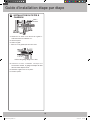
C1. PREPARING THE REAR WALL
FOR OUTSIDE BACK EXHAUST
You need to cut an opening in the rear wall for outside
exhaust.
C
L
• Read the instructions on the REAR WALL
TEMPLATE.
• Tape it to the rear wall.
• Cut the opening, following the instructions of the
REAR WALL TEMPLATE.
DE68-03587B-EN.indd 19 2008-12-09 �� 4:13:16

20
Step-by-step installation guide
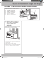
C2. ATTACH THE MOUNTING
PLATE TO THE WALL
Attach the plate to the wall using toggle bolts. At least
one wood screw must be used to attach the plate to a
wall stud.
1. Remove the toggle wings from the bolts.
2. Insert the bolts into the mounting plate through the
holes designated to go into drywall and reattach the
toggle wings to ¾” onto each bolt.
To use toggle bolts:
Wall
Toggle Wings
Toggle
Bolt
Bolt End
Spacing for Toggles More
Than Wall Thickness
Mounting
Plate
3. Place the mounting plate against the wall and insert
the toggle wings into the holes in the wall to mount
the plate.
NOTE: Before tightening toggle bolts and wood screw,
make sure the tabs on the mounting plate touch the
bottom of the cabinet when pushed flush against the
wall and that the plate is properly centered under the
cabinet.
CAUTION: Be careful to avoid pinching fingers
between the back of the mounting plate and the wall.
4. Tighten all bolts. Pull the plate away from the wall to
help tighten the bolts.
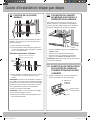
C3. USE TOP CABINET TEMPLATE
FOR PREPARATION OF TOP
CABINET
You need to drill holes for the top support screws, a
hole large enough for the power cord to fit through, and
a cutout large enough for the exhaust adaptor.
• Read the instructions on the TOP CABINET
TEMPLATE.
• Tape it underneath the top cabinet.
• Drill the holes, following the instructions on the TOP
CABINET TEMPLATE.
CAUTION: Wear safety goggles when drilling holes in
the cabinet bottom.
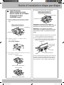
C4. ADAPTING MICROWAVE
BLOWER FOR OUTSIDE BACK
EXHAUST
1. Remove and save screws that hold the blower plate
and the blower motor to the microwave.
Back of
Microwave
Screw
Lift up the
blower plate.
2.
DE68-03587B-EN.indd 20 2008-12-09 �� 4:13:17
La page est en cours de chargement...
La page est en cours de chargement...
La page est en cours de chargement...
La page est en cours de chargement...
La page est en cours de chargement...
La page est en cours de chargement...
La page est en cours de chargement...
La page est en cours de chargement...
La page est en cours de chargement...
La page est en cours de chargement...
La page est en cours de chargement...
La page est en cours de chargement...
La page est en cours de chargement...
La page est en cours de chargement...
La page est en cours de chargement...
La page est en cours de chargement...
La page est en cours de chargement...
La page est en cours de chargement...
La page est en cours de chargement...
La page est en cours de chargement...
La page est en cours de chargement...
La page est en cours de chargement...
La page est en cours de chargement...
La page est en cours de chargement...
La page est en cours de chargement...
La page est en cours de chargement...
La page est en cours de chargement...
La page est en cours de chargement...
-
 1
1
-
 2
2
-
 3
3
-
 4
4
-
 5
5
-
 6
6
-
 7
7
-
 8
8
-
 9
9
-
 10
10
-
 11
11
-
 12
12
-
 13
13
-
 14
14
-
 15
15
-
 16
16
-
 17
17
-
 18
18
-
 19
19
-
 20
20
-
 21
21
-
 22
22
-
 23
23
-
 24
24
-
 25
25
-
 26
26
-
 27
27
-
 28
28
-
 29
29
-
 30
30
-
 31
31
-
 32
32
-
 33
33
-
 34
34
-
 35
35
-
 36
36
-
 37
37
-
 38
38
-
 39
39
-
 40
40
-
 41
41
-
 42
42
-
 43
43
-
 44
44
-
 45
45
-
 46
46
-
 47
47
-
 48
48


Samsung SMH1611W/XAC Guide d'installation
- Catégorie
- Fours
- Taper
- Guide d'installation
dans d''autres langues
Documents connexes
-
Samsung ME16K3000AW/AC Guide d'installation
-
Samsung SMH1713B/XAC Le manuel du propriétaire
-
-
-
Samsung ME17H703SHS/AC Guide d'installation
-
Samsung ME21M706BAG/AC Guide d'installation
-
-
-