Maytag EGD4400 Installation Instructions Manual
- Catégorie
- Sèche-linge
- Taper
- Installation Instructions Manual
Ce manuel convient également à

1
W10296135A
W10296136A-SP
Table of Contents
DRYER SAFETY ......................................................................... 1
INSTALLATION REQUIREMENTS ............................................. 4
Tools and Parts ......................................................................4
Location Requirements ......................................................... 4
ELECTRIC DRYER POWER HOOKUP - CANADA ONLY ........ 6
Electrical Requirements ........................................................6
INSTALL LEVELING LEGS ......................................................... 6
GAS DRYER POWER HOOKUP ................................................ 7
Gas Supply Requirements ..................................................... 7
VENTING .....................................................................................8
Venting Requirements ........................................................... 8
Plan Vent System ...................................................................9
Install Vent System .............................................................. 11
Level Dryer ...........................................................................11
Make Gas Connection ......................................................... 11
Connect Vent ........................................................................11
Complete Installation .......................................................... 11
Reverse Door Swing (Optional) ..........................................12
DRYER INSTALLATION INSTRUCTIONS
29" and 27" Wide Models
Gas (U.S.A. and Canada) & Electric (Canada Only)
INSTRUCTIONS D’INSTALLATION DE LA SÉCHEUSE
Modèles de 29" et de 27" de largeur
À gaz (É.-U. et Canada) et Électrique (Canada uniquement)
Para obtener acceso al manual de uso y cuidado en español, o para obtener información adicional acerca de su producto, visite:
www.whirlpool.com
Tenga listo su número de modelo completo. Puede encontrar el número de modelo y de serie dentro de la cavidad superior de la puerta.
DRYER SAFETY
You
You can be killed or seriously injured if you don't immediately
can be killed or seriously injured if you don't
follow
All safety messages will tell you what the potential hazard is, tell you how to reduce the chance of injury, and tell you what can
happen if the instructions are not followed.
Your safety and the safety of others are very important.
We have provided many important safety messages in this manual and on your appliance. Always read and obey all safety
messages.
This is the safety alert symbol.
This symbol alerts you to potential hazards that can kill or hurt you and others.
All safety messages will follow the safety alert symbol and either the word “DANGER” or “WARNING.”
These words mean:
follow instructions.
instructions.
DANGER
WARNING
Table des matières
SÉCURITÉ DE LA SÉCHEUSE ................................................14
EXIGENCES D'INSTALLATION ............................................... 17
Outillage et Pièces ............................................................... 17
Exigences d'emplacement .................................................. 17
RACCORDEMENT À L'ALIMENTATION ÉLECTRIQUE
DE LA SÉCHEUSE - CANADA SEULEMENT ......................... 19
Spécications Électriques .................................................. 19
INSTALLATION DES PIEDS DE NIVELLEMENT .................... 20
RACCORDEMENT D'UNE SÉCHEUSE À GAZ ......................20
Spécications de l'alimentation en gaz ............................. 20
ÉVACUATION ........................................................................... 22
Exigences concernant l'évacuation ...................................22
Planication du système d'évacuation .............................. 23
Installation du circuit d'évacuation .................................... 24
Réglage de l'aplomb de la sécheuse ................................. 25
RACCORDEMENT AU GAZ .................................................25
RACCORDEMENT DU CONDUIT D'ÉVACUATION ............ 25
ACHEVER L'INSTALLATION ................................................25
Inversion du sens d'ouverture
de la porte (facultatif) .......................................................... 26

2
WARNING: For your safety, the information in this manual must be followed to minimize
the risk of re or explosion, or to prevent property damage, personal injury, or death.
– Do not store or use gasoline or other ammable vapors and liquids in the vicinity of this
or any other appliance.
– WHAT TO DO IF YOU SMELL GAS:
•
Do not try to light any appliance.
•
Do not touch any electrical switch; do not use any phone in your building.
•
Immediately call your gas supplier from a neighbor's phone. Follow the gas supplier's
instructions.
•
If you cannot reach your gas supplier, call the re department.
– Installation and service must be performed by a qualied installer, service agency, or
the gas supplier.
•
Clear the room, building, or area of all occupants.
WARNING: Gas leaks cannot always be detected by smell.
Gas suppliers recommend that you use a gas detector approved by UL or CSA.
For more information, contact your gas supplier.
If a gas leak is detected, follow the “What to do if you smell gas” instructions.
IMPORTANT: The gas installation must conform with local codes, or in the absence of local codes, with the National Fuel Gas
Code, ANSI Z223.1/NFPA 54 or the Canadian Natural Gas and Propane Installation Code, CSA B149.1.
The dryer must be electrically grounded in accordance with local codes, or in the absence of local codes, with the National
Electrical Code, ANSI/NFPA 70 or Canadian Electrical Code, CSA C22.1.

3
In the State of Massachusetts, the following installation instructions apply:
� Installations and repairs must be performed by a qualied or licensed contractor, plumber, or gastter qualied or licensed by
the State of Massachusetts.
� If using a ball valve, it shall be a T-handle type.
� A exible gas connector, when used, must not exceed 3 feet.
IMPORTA NT SAFETY INSTRUCTIONS
When discarding or storing your old clothes dryer, remove the door.
SAVE THESE INSTRUCTIONS

4
INSTALLATION REQUIREMENTS
Tools and Parts
Gather the required tools and parts before starting installation.
Read and follow the instructions provided with any tools listed
here.
Flat-blade screwdriver ■
#2 Phillips head ■
screwdriver
Adjustable wrench that ■
opens to 1" (25 mm) or
hex-head socket wrench
(for adjusting dryer feet)
Level ■
Vent Clamps ■
Pliers ■
1/4" nut driver or socket ■
wrench (recommended)
Tin snips (new vent ■
installations)
Caulking gun and ■
compound (for installing
new exhaust vent)
Tape measure ■
Utility knife ■
Gas Installations
8" or 10" pipe wrench ■
8" or 10" adjustable ■
wrench
Pipe joint compound ■
resistant to LP gas
Parts supplied:
Parts package is located in dryer drum. Check that all parts
are included.
Parts needed:
Check local codes. Check existing electrical supply and venting,
and read “Electrical Requirements” and “Venting Requirements”
before purchasing parts.
Mobile home installations require metal exhaust system
hardware. For further information, please reference the
“Assistance or Service” section of the “Dryer User Instructions.”
Location Requirements
You will need:
A location allowing for proper exhaust installation. ■
See “Venting Requirements.”
A separate 30 amp circuit for electric dryers. ■
A separate 15 or 20 amp circuit for gas dryers. ■
If you are using power supply cord, a grounded electrical ■
outlet located within 2 ft. (610 mm) of either side of dryer.
See “Electrical Requirements.”
A sturdy oor to support dryer and a total weight (dryer ■
and load) of 200 lbs. (90.7 kg). The combined weight of a
companion appliance should also be considered.
Level oor with maximum slope of 1" (25 mm) under entire ■
dryer. If slope is greater than 1" (25 mm), install Extended
Dryer Feet Kit, Part Number 279810. If not level, clothes
may not tumble properly and automatic sensor cycles may
not operate correctly.
Do not operate your dryer at temperatures below 45°F (7°C). At
lower temperatures, the dryer might not shut off at the end of an
automatic cycle. Drying times can be extended.
The dryer must not be installed or stored in an area where it will
be exposed to water and/or weather.
Check code requirements. Some codes limit, or do not permit,
installation of the dryer in garages, closets, mobile homes, or
sleeping quarters. Contact your local building inspector.
NOTE: No other fuel-burning appliance can be installed in the
same closet as a dryer.
4 Leveling legs

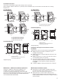
5
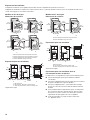
29" Wide Models
Dryer Dimensions
43
3
/
8
"
(1102 mm)
*26"
(660 mm)
29"
(737 mm)
A
15¼"
(387 mm)
43
3
/
8
"
(1102 mm)
*27¾"
(705 mm)
29"
(737 mm)
B
22¾"
(578 mm)
43
3
/
8
"
(1102 mm)
13¾"
(349 mm)
*27¾"
(705 mm)
29"
(737 mm)
D
43
3
/
8
"
(1102 mm)
*27¾"
(705 mm)
29"
(737 mm)
C
22¾"
(578 mm)
A. Small opening side-swing door
B. Large opening side-swing door
C. Wide opening side-swing door
D. Wide opening hamper door
Installation Spacing
A
B
C
18"*
(457 mm)
1"
(25 mm)
29"
(737 mm)
1"
(25 mm)
1"*
(25 mm)
14" max.*
(356 mm)
27¾"
(705 mm)
48 in.
(310 cm )
2
*
2
3"*
(76 mm)
3"*
(76 mm)
24 in.
(155 cm )
2
*
2
A. Recessed area
B. Side view - closet or conned area
C. Closet door with vents
*Required spacing
Installation clearances:
The location must be large enough to allow the dryer door to open fully.
Most installations require a minimum 5½" (140 mm) clearance behind the dryer for the exhaust vent with elbow. See “Venting
Requirements.”
27" Wide Models
Dryer Dimensions
43"
(1092 mm)
13¾"
(349 mm)
*29
1
/
2
"
(749 mm)
27"
(687 mm)
B
43"
(1092 mm)
*29
1
/
2
"
(749 mm)
27"
(687 mm)
A
23¾"
(603 mm)
A. Large opening side-swing door
B. Wide opening hamper door
Installation Spacing
A
B
C
18"*
(457 mm)
1"
(25 mm)
27"
(686 mm)
1"
(25 mm)
1"*
(25 mm)
14" max.*
(356 mm)
29
¼"
(743 mm)
5
½"*
(140 mm)
48 in.
(310 cm )
2
*
2
24 in.
(155 cm )
2
*
2
3"*
(76 mm)
3"*
(76 mm)
A. Recessed area
B. Side view - closet or conned area
C. Closet door with vents
*Required spacing
Installation spacing for recessed area or closet
installation
The dimensions shown are for the minimum spacing allowed.
Additional spacing should be considered for ease of ■
installation and servicing.
Additional clearances might be required for wall, door, and ■
oor moldings.
Additional spacing of 1" (25 mm) on all sides of the dryer is ■
recommended to reduce noise transfer.
For closet installation, with a door, minimum ventilation ■
openings in the top and bottom of the door are required.
Louvered doors with equivalent ventilation openings are
acceptable.
Companion appliance spacing should also be considered. ■
Mobile home - Additional installation requirements
This dryer is suitable for mobile home installations. The
installation must conform to the Manufactured Home
Construction and Safety Standard, Title 24 CFR, Part 3280
(formerly the Federal Standard for Mobile Home Construction and
Safety, Title 24, HUD Part 280) or the Canadian Manufactured
Home Standard CAN/CSA-Z240 MH.
Mobile home installations require:
Metal exhaust system hardware, available for purchase. ■
For further information, please reference the “Assistance or
Service” section of the “Dryer User Instructions.”
Special provisions must be made in mobile homes to ■
introduce outside air into the dryer. The opening (such as a
nearby window) should be at least twice as large as the dryer
exhaust opening.

6
4-wire receptacle (14-30R)
Do not use an extension cord. ■
If using a replacement power supply cord, it is recommended that
you use Power Supply Cord Replacement Part Number 3394208.
For further information, please reference the “Assistance or
Service” section of the “Dryer User Instructions.”
GROUNDING INSTRUCTIONS
SAVE THESE INSTRUCTIONS
�
For a grounded, cord-connected dryer:
This dryer must be grounded. In the event of malfunction or
breakdown, grounding will reduce the risk of electric shock
by providing a path of least resistance for electric current.
This dryer is equipped with a cord having an equipment-
grounding conductor and a grounding plug. The plug must
be plugged into an appropriate outlet that is properly
installed and grounded in accordance with all local codes
and ordinances.
WARNING: Improper connection of the equipment-
grounding conductor can result in a risk of electric shock.
Check with a qualied electrician or service representative
or personnel if you are in doubt as to whether the dryer is
properly grounded. Do not modify the plug provided with
the dryer: if it will not t the outlet, have a proper outlet
installed by a qualied electrician.
ELECTRIC DRYER POWER HOOKUP - CANADA ONLY
Electrical Requirements
WARNING
Electrical Shock Hazard
Plug into a grounded 4 prong outlet.
Failure to do so can result in death or electrical shock.
It is your responsibility:
To contact a qualied electrical installer. ■
To be sure that the electrical connection is adequate ■
and in conformance with the Canadian Electrical Code,
C22.1-latest edition and all local codes. A copy of the
above codes standard may be obtained from: Canadian
Standards Association, 178 Rexdale Blvd., Toronto, ON
M9W 1R3 CANADA.
To supply the required 4 wire, single phase, 120/240 volt, ■
60 Hz., AC only electrical supply on a separate 30-amp
circuit, fused on both sides of the line. A time-delay fuse or
circuit breaker is recommended. Connect to an individual
branch circuit.
This dryer is equipped with a CSA International Certied ■
Power Cord intended to be plugged into a standard 14-30R
wall receptacle. The cord is 5 ft. (1.52 m) in length. Be sure
wall receptacle is within reach of dryer’s nal location.
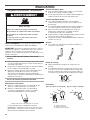
INSTALL LEVELING LEGS
WARNING
Excessive Weight Hazard
Use two or more people to move and install dryer.
Failure to do so can result in back or other injury.
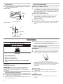
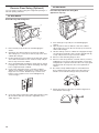
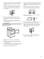
1. To avoid damaging the oor, use a large at piece of
cardboard from the dryer carton. Place cardboard under the
entire back edge of the dryer. See illustration.
2. Firmly grasp the body of the dryer (not the console panel).
Gently lay the dryer on the cardboard. See illustration.
3. Examine the leveling legs. Find the diamond marking.
4. Screw the legs into the leg holes by hand. Use a wrench to
nish turning the legs until the diamond marking is no longer
visible.
5. Place a carton corner post under each of the 2 dryer back
corners. Stand the dryer up. Slide the dryer on the corner
posts until it is close to its nal location. Leave enough room
to connect the exhaust vent.
6. Once connection is made and dryer is in nal location,
remove corner posts and cardboard.
For mobile home use
Gas dryers must be securely fastened to the oor.
Mobile home installations require a Mobile Home Installation
Hold-down Kit. For ordering information please reference the
“Dryer User Instructions.”

7
GAS DRYER POWER HOOKUP
Gas Supply Requirements
WARNING
Explosion Hazard
Use a new CSA International approved gas supply line.
Install a shut-off valve.
Securely tighten all gas connections.
If connected to LP, have a qualied person make sure
gas pressure does not exceed 13" (330 mm) water
column.
Examples of a qualied person include:
licensed heating personnel,
authorized gas company personnel, and
authorized service personnel.
Failure to do so can result in death, explosion, or re.
Gas type
Natural gas:
This dryer is equipped for use with Natural Gas. It is design-
certied by CSA International for LP (propane or butane) gases
with appropriate conversion.
Your dryer must have the correct burner for the type of gas ■
in your home. Burner information is located on the rating
plate in the door well of your dryer. If this information does
not agree with the type of gas available, please reference
the “Assistance or Service” section of the “Dryer User
Instructions.”
LP gas conversion:
Conversion must be made by a qualied technician.
No attempt shall be made to convert the dryer from the gas
specied on the model/serial rating plate for use with a different
gas without consulting the serving gas supplier.
IMPORTANT: The gas installation must conform with local codes,
or in the absence of local codes, with the National Fuel Gas
Code, ANSI Z223.1/NFPA 54 or the Canadian Natural Gas and
Propane Installation Code, CSA B149.1.
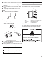
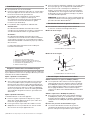
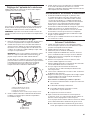
Gas supply line
1/2" NPT pipe is recommended. ■
3/8" approved tubing is acceptable for lengths under ■
20 ft. (6.1 m) if local codes and gas supplier permit.
Must include 1/8" NPT minimum plugged tapping accessible ■
for test gauge connection, immediately upstream of the gas
connection to the dryer (see illustration).
Must include a shutoff valve: ■
In the U.S.A.:
An individual manual shutoff valve must be installed within
six (6) feet (1.8 m) of the dryer in accordance with the
National Fuel Gas Code, ANSI Z223.1.
In Canada:
An individual manual shutoff valve must be installed in
accordance with the B149.1, Natural Gas and Propane
Installation Code. It is recommended that an individual
manual shutoff valve be installed within six (6) feet (1.8 m)
of the dryer.
The shut off valve location should be easy to reach for opening
and closing.
A
B
E
D
C
A. 3/8" exible gas connector
B. 3/8" pipe to are adapter tting
C. 1/8" NPT minimum plugged tapping
D. 1/2" NPT gas supply line
E. Gas shutoff valve
Gas supply connection requirements
There are many methods by which your gas dryer can be
connected to the gas supply. Listed here are some guidelines
for two different methods of connection.
Option 1 (Recommended Method)
Flexible stainless steel gas connector:
If local codes permit, use a new exible stainless steel gas ■
connector (Design Certied by the American Gas Association
or CSA International) to connect your dryer to the rigid gas
supply line. Use an elbow and a 3/8" are x 3/8" NPT adapter
tting between the stainless steel gas connector and the
dryer gas pipe, as needed to prevent kinking.
Option 2 (Alternate Method)
Approved aluminum or copper tubing:
Lengths over 20 ft. (6.1 m) can use 3/8" approved tubing ■
(if codes and gas supplier permit).
If you are using Natural Gas, do not use copper tubing. ■
3/8" are x 3/8" NPT adapter tting between dryer pipe and ■
3/8" approved tubing.
Lengths over 20 ft. (6.1 m) should use larger tubing and a ■
different size adapter tting.
If your dryer has been converted to use LP gas, 3/8" LP ■
compatible copper tubing can be used. If the total length
of the supply line is more than 20 ft. (6.1 m), use larger pipe.
NOTE: Pipe joint compounds that resist the action of LP
gas must be used. Do not use TEFLON
®†
tape.
†®TEFLON is a registered trademark of E.I. Du Pont De Nemours and Company.

8
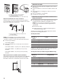
Dryer gas pipe
The gas pipe that comes out through the rear of your dryer ■
has a 3/8" male pipe thread.
29" Wide Model
A
1¼"
(32 mm)
9¼"
(235 mm)
A. 3/8" NPT dryer pipe
27" Wide Model
A
*6¼"
(159 mm)
1½"
(38 mm)
A. 3/8" NPT dryer pipe
A. 3/8" NPT dryer pipe
Burner input requirements
Elevations up to 10,000 ft. (3,048 m):
The design of this dryer is certied by CSA International for ■
use at altitudes up to 10,000 ft. (3,048 m), above sea level at
the B.T.U. rating indicated on the model/serial number plate.
Burner input adjustments are not required when the dryer is
operated up to this elevation.
Elevations above 10,000 ft. (3,048 m):
When installed above 10,000 ft. (3,048 m) a 4% reduction ■
of the burner B.T.U. rating shown on the model/serial
number plate is required for each 1,000 ft. (305 m)
increase in elevation.
Gas supply pressure testing
The dryer must be disconnected from the gas supply piping ■
system during pressure testing at pressures greater than
1/2 psi.
Venting Requirements
WARNING
Fire Hazard
Use a heavy metal vent.
Do not use a plastic vent.
Do not use a metal foil vent.
Failure to follow these instructions can result in death
or re.
VENTING
WARNING: To reduce the risk of re, this dryer MUST BE
EXHAUSTED OUTDOORS.
IMPORTANT: Observe all governing codes and ordinances.
Dryer exhaust must not be connected into any gas vent,
chimney, wall, ceiling, attic, crawlspace, or a concealed space
of a building.
If using an existing vent system
Clean lint from the entire length of the system and make sure ■
exhaust hood is not plugged with lint.
Replace any plastic or metal foil vent with rigid heavy metal ■
vent or exible metal vent.
Review Vent system chart. Modify existing vent system if ■
necessary to achieve the best drying performance. Only rigid
or exible metal vent shall be used for exhausting.
If this is a new vent system
Vent Material
Use a heavy metal vent. Do not use plastic or metal foil vent. ■
4" (102 mm) heavy metal exhaust vent and clamps must be ■
used. DURASAFE™ venting products are recommended.
4" (102 mm) heavy metal exhaust vent
DURASAFE™ vent products can be purchased by calling
the toll-free number. For further information, please reference
the “Assistance or Service” section of the “Dryer User
Instructions.”
Rigid metal vent:
For best drying performance, rigid metal vents are ■
recommended.
Rigid metal vent is recommended to avoid crushing and ■
kinking.
Flexible metal vent:
Flexible metal vents are acceptable only if accessible for ■
cleaning.

9
Must be fully extended and supported when the dryer is in its ■
nal location.
Remove excess exible metal vent to avoid sagging ■
and kinking that may result in reduced airow and poor
performance.
Do not install exible metal vent in enclosed walls, ceilings, ■
or oors.
The total length of exible metal duct shall not exceed ■
7¾ ft. (2.4 m).
Elbows:
45° elbows provide better airow than 90° elbows. ■
Clamps:
Use clamps to seal all joints. ■
Exhaust vent must not be connected or secured with screws ■
or other fastening devices that extend into interior of duct
and catch lint. Do not use duct tape.
Clamp
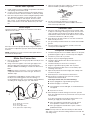
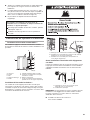
Exhaust:
Recommended hood styles. Acceptable hood style.
4"
(102 mm)
2
½"
(64 mm)
4"
(102 mm)
4"
(102 mm)
B
A
C
A. Louvered hood style
B. Box hood style
C. Angled hood style is acceptable
An exhaust hood should cap the vent to keep rodents and ■
insects from entering the home.
Exhaust hood must be at least 12" (305 mm) from the ground ■
or any object that may be in the path of the exhaust (such as
owers, rocks or bushes, snow line, etc.).
Do not use an exhaust hood with a magnetic latch. ■
Improper venting can cause moisture and lint to collect
indoors, which may result in:
Moisture damage to woodwork, furniture, paint, wallpaper,
carpets, etc.
Housecleaning problems and health problems.
Good Better
Plan Vent System
Recommended exhaust installations
Typical installations vent the dryer from the rear of the dryer.
Other installations are possible.
A
B
B
C
D
E
F
G
H
I
A. Dryer
B. Elbow
C. Wall
D. Exhaust hood
E. Clamps
F. Rigid metal or exible metal vent
G. Vent length necessary to connect elbows
H. Exhaust outlet
I. Optional side exhaust outlet
(27" wide models only)
Optional exhaust installations:
27" Wide Models can be converted to exhaust out the right
side, left side, or through the bottom. Each kit includes step-by-
step instructions. For further information, please reference the
“Assistance or Service” section of the “Dryer User Instructions.”

10
AB
A. Standard rear offset exhaust installation
B. Left or right side exhaust installation
(27" wide models only)
C. Bottom exhaust installation (27" wide models only)
Alternate installations for close clearances
Venting systems come in many varieties. Select the type best
for your installation. Two close-clearance installations are shown.
Refer to the manufacturer’s instructions.
AB
A. Over-The-Top installation (also available with
one offset elbow)
B. Periscope installation
NOTE: The following kits for close clearance alternate
installations are available for purchase. Please see the
“Assistance or Service” section of the “Dryer User Instructions.”
Over-the-Top Installation: ■
Part Number 4396028
Periscope Installation (For use with dryer vent to wall vent ■
mismatch):
Part Number 4396037 - 0" (0 mm) to 18" (460 mm) mismatch
Part Number 4396011 - 18" (460 mm) to 29" (737 mm)
mismatch
Part Number 4396014 - 29" (737 mm) to 50" (1270 mm)
mismatch
Special provisions for mobile home installations:
The exhaust vent must be securely fastened to a noncombustible
portion of the mobile home structure and must not terminate
beneath the mobile home. Terminate the exhaust vent outside.
C
D
Determine vent path:
Select the route that will provide straightest and most direct ■
path outdoors.
Plan the installation to use the fewest number of elbows and ■
turns.
When using elbows or making turns, allow as much room ■
as possible.
Bend vent gradually to avoid kinking. ■
Avoid 90° turns when possible. ■
Determine vent length and elbows needed for best
drying performance:
Use following Vent system chart to determine type of vent ■
material and hood combinations acceptable to use.
NOTE: Do not use vent runs longer than those specied
in Vent system chart. Exhaust systems longer than those
specied will:
Shorten life of dryer. ■
Reduce performance, resulting in longer drying times ■
and increased energy usage.
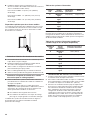
The Vent system chart provides venting requirements that will
help achieve best drying performance.
Vent System Chart
Number
90° turns or
elbows
Type of vent Box/louvered
hoods
Angled hoods
0 Rigid metal 64 ft. (20 m) 58 ft. (17.7 m)
1 Rigid metal 54 ft. (16.5 m) 48 ft. (14.6 m)
2 Rigid metal 44 ft. (13.4 m) 38 ft. (11.6 m)
3 Rigid metal 35 ft. (10.7 m) 29 ft. (8.8 m)
4 Rigid metal 27 ft. (8.2 m) 21 ft. (6.4 m)
NOTE: Side and bottom exhaust installations for 27" wide
models have a 90º turn inside the dryer. To determine maximum
exhaust length, add one 90º turn to the chart.
Vent System Chart (29" Wide Long Vent Models Only)
Number
90° turns or
elbows
Type of vent Box, louvered,
or angled hoods
0 Rigid metal 120 ft. (36.6 m)
1 Rigid metal 110 ft. (33.5 m)
2 Rigid metal 100 ft. (30.5 m)
3 Rigid metal 90 ft. (27.4 m)
4 Rigid metal 80 ft. (24.4 m)
5 Rigid metal 70 ft. (21.3 m)

11
Install Vent System
1. Install exhaust hood. Use caulking compound to seal exterior
wall opening around exhaust hood.
2. Connect vent to exhaust hood. Vent must t inside exhaust
hood. Secure vent to exhaust hood with 4" (102 mm) clamp.
3. Run vent to dryer location. Use the straightest path possible.
See “Determine vent path” in “Plan Vent System.” Avoid
90º turns. Use clamps to seal all joints. Do not use duct
tape, screws, or other fastening devices that extend into the
interior of the vent to secure vent, because they can catch
lint.
Level Dryer
Check the levelness of the dryer. Check levelness rst side to
side, then front to back.
If the dryer is not level, prop up the dryer using a wood block.
Use a wrench to adjust the legs up or down and check again for
levelness.
NOTE: It might be necessary to level the dryer again after it is
moved into its nal position.
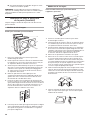
Make Gas Connection
1. Remove the red cap from the gas pipe. Move the dryer close
to its nal position.
2. Using a wrench to tighten, connect the gas supply to the
dryer. Use pipe joint compound on all non-ared male
threads. If exible metal tubing is used, be sure there are no
kinks.
NOTE: For LP gas connections, you must use pipe joint
compound resistant to the action of LP gas. Do not use
TEFLON
®†
tape.
A combination of pipe ttings must be used to connect
the dryer to the existing gas line. Shown following is a
recommended connection. Your connection may be different,
according to the supply line type, size, and location.
A
B
C
D
A. 3/8" exible gas connector
B. 3/8" dryer pipe
C. 3/8" to 3/8" pipe elbow
D. 3/8" pipe-to-are adapter tting
3. Open the shutoff valve in the supply line. The valve is open
when the handle is parallel to the gas pipe.
A
B
A. Closed valve
B. Open valve
4. Test all connections by brushing on an approved
noncorrosive leak-detection solution. Bubbles will show a
leak. Correct any leak found.
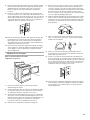
Connect Vent
1. Using a 4" (102 mm) clamp, connect vent to exhaust outlet
in dryer. If connecting to existing vent, make sure the vent is
clean. The dryer vent must t over the dryer exhaust outlet
and inside the exhaust hood. Check that the vent is secured
to exhaust hood with a 4" (102 mm) clamp.
2. Move dryer into its nal location. Do not crush or kink vent.
Make sure dryer is level.
3. (On gas models) Check that there are no kinks in the exible
gas line.
4. Once the exhaust vent connection is made, remove the
corner posts and cardboard.
Complete Installation
1. Check that all parts are now installed. If there is an extra part,
go back through the steps to see which step was skipped.
2. Check that you have all of your tools.
3. Dispose of/recycle all packaging materials.
4. Check the dryer’s nal location. Be sure the vent is not
crushed or kinked.
5. Check that the dryer is level. See “Level Dryer.”
6. Plug into a grounded 3 prong outlet. Turn on power.
7. Remove the protective lm on the console and any tape
remaining on the dryer.
8. Wipe the dryer drum interior thoroughly with a damp cloth
to remove any dust.
9. Read “Dryer Use” in the “Dryer User Instructions”.
10. Set the dryer on a full heat cycle (not an air cycle) for
20 minutes and start the dryer.
If the dryer will not start, check the following:
Dryer is plugged into a grounded 3 prong outlet. ■
Electrical supply is connected. ■
Household fuse is intact and tight, or circuit breaker has ■
not tripped.
Dryer door is closed. ■
11. When the dryer has been running for 5 minutes, open the
dryer door and feel for heat. If you feel heat, cancel cycle and
close the door.
If you do not feel heat, turn the dryer off and check to see
whether gas supply line shutoff valve is open.
If the gas supply line shutoff valve is closed, open it, ■
then repeat the 5-minute test as outlined above.
If the gas supply line shutoff valve is open, contact a ■
qualied technician.
NOTE: You may notice an odor when the dryer is rst heated.
This odor is common when the heating element is rst used. The
odor will go away.

12
Reverse Door Swing (Optional)
You can change your door swing from a right-side opening to a
left-side opening, if desired.
29" Wide Models
Reversible Large Side Swing Door
A
B
C
D
1. Place towel (A) on top of dryer to avoid damaging the
surface.
2. Open dryer door. Remove bottom screws from cabinet
side of hinges (C). Loosen (do not remove) top screws from
cabinet side of hinges.
3. Lift door until top screws in cabinet are in large part of hinge
slot. Pull door forward off screws. Set door on top of dryer.
Remove top screws from cabinet.
4. Use a small, at-blade screwdriver to gently remove 4 hinge
hole plugs (D) on left side of cabinet. Insert plugs into hinge
holes on right-hand side of cabinet.
5. Insert screws into bottom holes on left side of cabinet.
Tighten screws halfway. Position door so large end of door
hinge slot is over screws. Slide door up so screws are in
bottom of slots. Tighten screws. Insert and tighten top
screws in hinges.
6. Close door and check that door strike aligns with door catch
(B). If needed, slide door catch left or right within slot to
adjust alignment.
29" Wide Models
Reversible Super Wide Side-Swing Door
Appearance may vary
A
C
B
D
F
E
1. Place towel (A) on top of dryer to avoid damaging the
surface.
2. Open dryer door. Remove bottom screws from cabinet
side of hinges (D). Loosen (do not remove) top screws from
cabinet side of hinges.
3. Lift door until top screws in cabinet are in large part of hinge
slot. Pull door forward off screws. Set door (handle side up)
on top of dryer. Remove top screws from cabinet.
4. Remove screws attaching hinges to door.
5. Remove screws at top, bottom, and side of door (4 screws).
Holding door over towel on dryer, grasp sides of outer door
and gently lift to separate it from inner door. Do not pry apart
with putty knife. Do not pull on door seal or plastic door
catches.
6. Be certain to keep cardboard spacer centered between
doors. Reattach outer door panel to inner door panel so
handle is on the side where hinges were just removed.
7. Attach door hinges to dryer door so that the larger hole is
at the bottom of the hinge.

13
8. Remove door strike (E) from cabinet. Use a small, at-blade
screwdriver to gently remove 4 hinge hole plugs (F) on left
side of cabinet. Insert plugs into hinge holes on right side
of cabinet.
9. Insert screws into bottom holes on left side of cabinet.
Tighten screws halfway. Position door so large end of door
hinge slot is over screws. Slide door up so screws are in
bottom of slots. Tighten screws. Insert and tighten top
screws in hinges.
10. Remove door strike plug (B). Insert the door strike you
removed in Step 8 into hole and secure with screw. Insert
door strike plug into original door strike hole and secure
with screw.
11. Close door and check that door strike aligns with door
catch (C). If it is needed, slide door catch left or right within
slot to adjust alignment.
27" Wide Models
Reversible Side-Swing Door
Appearance may vary
B
D
C
A
1. Place towel (A) on top of dryer to avoid damaging the
surface.
2. Open dryer door. Remove bottom screws from cabinet
side of hinges (B). Loosen (do not remove) top screws from
cabinet side of hinges.
3. Lift door until top screws in cabinet are in large part of hinge
slot. Pull door forward off screws. Set door (handle side up)
on top of dryer. Remove top screws from cabinet.
4. Remove screws attaching hinges to door.
5. Remove screws at top, bottom, and side of door (4 screws).
Holding door over towel on dryer, grasp sides of outer door
and gently lift to separate it from inner door. Do not pry apart
with putty knife. Do not pull on door seal or plastic door
catches.
6. Be certain to keep cardboard spacer centered between
doors. Reattach outer door panel to inner door panel so
handle is on the side where hinges were just removed.
7. Attach door hinges to dryer door so that the larger hole is
at the bottom of the hinge.
8. Remove the 4 screws that attach 2 plugs (D) on the left side.
Attach plugs to right side using the same 4 screws.
9. Insert screws into bottom holes on left side of cabinet.
Tighten screws halfway. Position door so large end of door
hinge slot is over screws. Slide door up so screws are in
bottom of slots. Tighten screws. Insert and tighten top
screws in hinges.
10. Close door and check that door strike aligns with door
catch (C). If it is needed, slide door catch left or right
within slot to adjust alignment.

14
SÉCURITÉ DE LA SÉCHEUSE
Risque possible de décès ou de blessure grave si vous ne
suivez pas immédiatement les instructions.
Risque possible de décès ou de blessure grave si vous
ne suivez pas les instructions.
Tous les messages de sécurité vous diront quel est le danger potentiel et vous disent comment réduire le risque de blessure et
ce qui peut se produire en cas de non-respect des instructions.
Votre sécurité et celle des autres est très importante.
Nous donnons de nombreux messages de sécurité importants dans ce manuel et sur votre appareil ménager. Assurez-vous de
toujours lire tous les messages de sécurité et de vous y conformer.
AVERTISSEMENT
DANGER
Voici le symbole d’alerte de sécurité.
Ce symbole d’alerte de sécurité vous signale les dangers potentiels de décès et de blessures graves à vous
et à d’autres.
Tous les messages de sécurité suivront le symbole d’alerte de sécurité et le mot “DANGER” ou
“AVERTISSEMENT”. Ces mots signient :
IMPORTANT : L'installation du gaz doit se conformer aux codes locaux, ou en l'absence de codes locaux, au National Fuel Gas
Code, ANSI Z223.1/NFPA 54.
La sécheuse doit être électriquement reliée à la terre conformément aux codes locaux, ou en l'absence de codes locaux, au Code
canadien de l'électricité, ANSI/NFPA 70.

15
IMPORTANTES INSTRUCTIONS DE SÉCURITÉ
Pour réduire le risque d'incendie, de choc électrique ou de blessure lors de l'utilisation de
la sécheuse, il convient d'observer certaines précautions élémentaires dont les suivantes :
AVERTISSEMENT :
� Lire toutes les instructions avant d'utiliser la sécheuse.
� Ne pas placer des articles exposés aux huiles de cuisson
dans votre sécheuse. Les articles contaminés par des
huiles de cuisson peuvent contribuer à une réaction
chimique qui pourrait causer à la charge de s'enammer.
� Ne pas faire sécher dans la machine des articles qui ont
déjà été nettoyés, lavés, imbibés, ou tachés d'essence,
de solvants pour nettoyage à sec, d'autres substances
inammables, ou de substances explosives puisqu'elles
dégagent des vapeurs qui peuvent provoquer un
incendie ou une explosion.
� Ne pas permettre à des enfants de jouer sur ou à
l'intérieur de la sécheuse. Une surveillance étroite est
nécessaire lorsque la sécheuse est utilisée près d'eux.
� Avant d'enlever la sécheuse du service ou la jeter, enlever
la porte du compartiment de séchage.
�
Ne pas mettre la main dans la sécheuse si le tambour est
en mouvement.
� Ne pas réparer ni remplacer une pièce de la sécheuse ou
essayer d'en faire l'entretien à moins d'une recommandation
spécique dans le guide d'utlilisation et d'entretien, ou
publiée dans les instructions de réparation par l'utilisateur
que vous comprenez et pouvez exécuter avec compétence.
CONSERVEZ CES INSTRUCTIONS
�
Ne pas installer ni entreposer la sécheuse où elle sera
exposée aux intempéries.
� Ne pas jouer avec les commandes.
� Ne pas utiliser un produit assouplissant de tissu ou des
produits pour éliminer la statique à moins qu'ils ne soient
recommandés par le fabricant du produit assouplissant de
tissu ou du produit.
� Ne pas utiliser la chaleur pour faire sécher des articles
fabriqués avec du caoutchouc mousse ou des matériaux
semblables.
� Nettoyer le ltre à charpie avant et après chaque charge.
� Ne pas laisser la charpie, la poussière, ou la saleté
s'accumuler autour du système d'évacuation ou autour de
l'appareil.
� Un nettoyage périodique de l'intérieur de la sécheuse et du
conduit d'évacuation doit être effectué par une personne
qualiée.
� Voir les instructions d'installation pour les exigences de
liaison de l'appareil à la terre.
AVERTISSEMENT : L’odorat ne permet pas toujours la détection d’une fuite de gaz.
Les distributeurs de gaz recommandent l’emploi d’un détecteur de gaz (homologation UL ou CSA).
Pour d’autre information, contacter le fournisseur de gaz local.
En cas de détection d’une fuite de gaz, exécuter les instructions “Que faire dans le cas d’une odeur de gaz”.

16
Dans l’État du Massachusetts, les instructions d’installation suivantes sont applicables :
■ Les travaux d’installation et réparation doivent être exécutés par un plombier ou tuyauteur qualifié ou licencié, ou par le
personnel qualifié d’une entreprise licenciée par l’État du Massachusetts.
■ Si une vanne à boisseau sphérique est utilisée, elle doit comporter une manette “T”.
■ Si un conduit de raccordement flexible est utilisé, sa longueur ne doit pas dépasser 3 pi.
Avertissements de la proposition 65 de l'État de Californie :
AVERTISSEMENT : Ce produit contient un produit chimique connu par l’État de Californie pour être à l’origine de cancers.
AVERTISSEMENT : Ce produit contient un produit chimique connu par l’État de Californie pour être à l’origine de malformations
et autres déciences de naissance.

17
EXIGENCES D'INSTALLATION
Outillage et Pièces
Rassembler les outils et composants nécessaires avant
d'entreprendre l'installation. Lire et suivre les instructions fournies
avec chacun des outils de la liste ci-dessous.
Tournevis à lame plate ■
Tournevis Phillips n° 2 ■
Clé à molette avec ■
ouverture jusqu'à
1" (25 mm) ou clé à
douille à tête hexagonale
(pour le réglage des pieds
de la sécheuse)
Niveau ■
Pince ■
Brides de serrage ■
Tourne-écrou de ■
1/4" ou clé à douille
(recommandé)
Cisaille de ferblantier ■
(pour l'installation d'un
nouveau conduit)
Pistolet à calfeutrage et ■
composé de calfeutrage
(pour l'installation
d'un nouveau conduit
d'évacuation)
Mètre ruban ■
Couteau utilitaire ■
Installations au gaz
Clé à tuyau de 8" ou 10" ■
Clé à molette de 8" ou 10" ■
Composé d'étanchéité ■
des raccords letés –
résistant au gaz propane
Pièces fournies :
Le sachet de pièces se trouve dans le tambour de la sécheuse.
Vérier que toutes les pièces sont présentes.
Pièces nécessaires :
Consulter les codes locaux. Vérier l'alimentation électrique
et le circuit d'évacuation existants. Voir “Spécications
électriques” et “Exigences concernant l'évacuation” avant
d'acheter les pièces.
Pour les installations en résidence mobile, le circuit d'évacuation
nécessite des matériaux métalliques. Pour plus d'informations,
consulter la section “Assistance ou service” dans “Instructions
d'utilisation de la sécheuse”.
Exigences d'emplacement
Il vous faudra :
Un emplacement permettant une évacuation appropriée. ■
Voir “Exigences concernant l'évacuation”.
Un circuit distinct de 30 ampères pour les sécheuses ■
électriques.
Un circuit distinct de 15 ou 20 ampères pour les sécheuses ■
à gaz.
Si on utilise un cordon d'alimentation, une prise électrique ■
avec liaison à la terre située à moins de 2 pi (610 mm) de
l'un des côtés de la sécheuse. Voir “Spécications
électriques”.
Un plancher robuste capable de supporter le poids de ■
la sécheuse (sécheuse et charge) de 200 lb. (90,7 kg).
Il faut aussi prendre en compte le poids combiné d'un
appareil ménager voisin.
Un plancher de niveau ayant une pente maximale de ■
1" (25 mm) sous l'ensemble de la sécheuse. Si la pente
est supérieure à 1" (25 mm), installer un ensemble de
pieds d'extension pour sécheuse, pièce n° 279810. Si
la sécheuse n'est pas d'aplomb, le linge peut ne pas
culbuter convenablement, et les programmes automatiques
de détection peuvent ne pas fonctionner correctement.
Ne pas faire fonctionner la sécheuse à une température inférieure
à 45°F (7°C). À des températures inférieures, la sécheuse risque
de ne plus s'arrêter à la n d'un programme automatique. Les
temps de séchage risquent alors d'augmenter.
La sécheuse ne doit pas être installée ou remisée dans un endroit
où elle sera exposée à l'eau et/ou aux intempéries.
Vérier les règlements locaux. Certains codes limitent ou
n'autorisent pas l'installation des sécheuses dans un garage,
un placard, une maison mobile ou une chambre à coucher.
Communiquer avec l'inspecteur des bâtiments local.
REMARQUE : Aucun autre appareil consommant un combustible
ne doit être installé dans le même placard que la sécheuse.
Pieds de nivellement (4)

18
Modèles de 29" de largeur
Dimensions de sécheuse
43
3
/
8
"
(1102 mm)
*26"
(660 mm)
29"
(737 mm)
A
15¼"
(387 mm)
43
3
/
8
"
(1102 mm)
*27¾"
(705 mm)
29"
(737 mm)
B
22¾"
(578 mm)
43
3
/
8
"
(1102 mm)
13¾"
(349 mm)
*27¾"
(705 mm)
29"
(737 mm)
D
43
3
/
8
"
(1102 mm)
*27¾"
(705 mm)
29"
(737 mm)
C
22¾"
(578 mm)
A. Porte à pivotement latéral à petite ouverture
B. Porte à pivotement latéral à grande ouverture
C. Porte à pivotement latéral à large ouverture
D. Porte rabattable à large ouverture
Espacement pour une installation
A
B
C
18"*
(457 mm)
1"
(25 mm)
29"
(737 mm)
1"
(25 mm)
1"*
(25 mm)
14" max.*
(356 mm)
27¾"
(705 mm)
48 in.
(310 cm )
2
*
2
3"*
(76 mm)
3"*
(76 mm)
24 in.
(155 cm )
2
*
2
A. Encastrement
B. Vue latérale - placard ou endroit exigu
C. Porte du placard avec orices d'entrée d'air
*Espacement requis
Modèles de 27" de largeur
Dimensions de sécheuse
43"
(1092 mm)
13¾"
(349 mm)
*29
1
/
2
"
(749 mm)
27"
(687 mm)
B
43"
(1092 mm)
*29
1
/
2
"
(749 mm)
27"
(687 mm)
A
23¾"
(603 mm)
A. Porte à pivotement latéral à large ouverture
B. Porte rabattable à large ouverture
Espacement pour une installation
A
B
C
18"*
(457 mm)
1"
(25 mm)
27"
(686 mm)
1"
(25 mm)
1"*
(25 mm)
14" max.*
(356 mm)
29
¼"
(743 mm)
5
½"*
(140 mm)
48 in.
(310 cm )
2
*
2
24 in.
(155 cm )
2
*
2
3"*
(76 mm)
3"*
(76 mm)
A. Encastrement
B. Vue latérale - placard ou endroit exigu
C. Porte du placard avec orices d'entrée d'air
*Espacement requis
Espacement pour une installation dans un
encastrement ou dans un placard
Les dimensions correspondent à l'espacement minimum permis.
Prévoir davantage d'espace pour faciliter l'installation ■
et l'entretien.
Un espace supplémentaire peut être requis pour les moulures ■
de porte et de plancher et pour les plinthes.
Un espace supplémentaire 1" (25 mm) doit être envisagé ■
de tous les côtés de la sécheuse an de réduire le transfert
de bruit.
Pour installation dans un placard avec porte, on doit prévoir ■
des ouvertures minimums d'entrée d'air en haut et en bas
de la porte. Les portes à claire-voie offrant des ouvertures
équivalentes de passage de l'air sont acceptables.
Il faut aussi prendre en compte l'espace requis entre ■
les appareils voisins.
Espacements d'installation :
L'emplacement doit être assez grand pour permettre d'ouvrir complètement la porte de la sécheuse.
La plupart des installations requièrent un espace minimum de 5½" (140 mm) derrière la sécheuse pour le conduit d'évacuation avec
coude. Voir “Exigences concernant l'évacuation”.

19
RACCORDEMENT À L'ALIMENTATION ÉLECTRIQUE
DE LA SÉCHEUSE - CANADA SEULEMENT
Spécications Électriques
AVERTISSEMENT
Risque de choc électrique
Brancher sur une prise à 4 alvéoles reliée à la terre.
Le non-respect de cette instruction peut causer
un décès ou un choc électrique.
C'est à l'utilisateur qu'incombe la responsabilité de :
Contacter un électricien qualié. ■
S'assurer que le raccordement électrique est adéquat ■
et conforme au Code canadien de l'électricité, C22.1 –
dernière édition, et à tous les codes locaux en vigueur.
Pour obtenir un exemplaire des normes des codes ci-dessus,
contacter : Canadian Standards Association, 178 Rexdale
Blvd., Toronto, ON M9W 1R3 CANADA.
L'appareil doit être alimenté uniquement par un circuit ■
monophasé de 120/240 V CA seulement, 60 Hz à 4 ls,
sur un circuit séparé de 30 ampères, fusionné aux deux
extrémités de la ligne. On recommande d'utiliser un fusible
ou un disjoncteur temporisé. On recommande également
que cet appareil soit alimenté par un circuit indépendant.
Cette sécheuse est équipée d'un cordon d'alimentation ■
homologué par la CSA International à introduire dans
une prise murale standard 14-30R. Le cordon mesure
5 pi (1,52 m). Veiller à ce que la prise murale se trouve
à proximité de l'emplacement dénitif de la sécheuse.
Prise murale à 4 ls (14-30R)
Ne pas utiliser de câble de rallonge. ■
En cas d'utilisation d'un cordon d'alimentation de rechange,
il est conseillé d'utiliser le cordon d'alimentation de rechange
- pièce numéro 3394208. Pour plus d'information, consulter la
section “Assistance ou service” dans “Instructions d'utilisation
de la sécheuse”.
Pour une sécheuse reliée à la terre et connectée par
un cordon :
Cette sécheuse doit être reliée à la terre. En cas de mauvais
fonctionnement ou de panne, la liaison à la terre réduira le
risque de choc électrique en offrant au courant électrique un
acheminement d'évacuation de moindre résistance. Cette
sécheuse est alimentée par un cordon électrique comportant
un conducteur relié à la terre et une che de branchement
munie d'une broche de liaison à la terre. La che doit être
branchée sur une prise appropriée qui est bien installée et
reliée à la terre conformément à tous les codes et règlements
locaux.
INSTRUCTIONS DE LIAISON À LA TERRE
CONSERVEZ CES INSTRUCTIONS
AVERTISSEMENT : Le raccordement incorrect de
cet appareil au conducteur de liaison à la terre peut susciter
un risque de choc électrique. En cas de doute quant à la
qualité de liaison à la terre de la sécheuse, consulter un
électricien ou un technicien ou un personnel qualié. Ne pas
modier la che de branchement fournie avec la sécheuse;
si la che ne correspond pas à la conguration de la prise de
courant, demander à un électricien qualié d'installer une
prise de courant appropriée.
Installation dans une maison mobile – exigences
supplémentaires
Cette sécheuse peut être installée dans une maison mobile.
L'installation doit satisfaire aux critères du Manufactured Home
Construction and Safety Standard, Titre 24 CFR, Partie 3280
(anciennement Federal Standard for Mobile Home Construction
and Safety, Titre 24, HUD Partie 280) ou du Canadian
Manufactured Home Standard CAN/CSA-Z240 MH.
Autres critères à respecter pour une installation en
résidence mobile :
Un matériel d'évacuation métallique, disponible à l'achat. ■
Pour plus d'informations, consulter la section “Assistance
ou service” dans “Instructions d'utilisation de la sécheuse”.
Il faut prendre des dispositions spéciales dans les maisons ■
mobiles pour l'apport d'air de l'extérieur dans la sécheuse.
L'ouverture (telle qu'une fenêtre à proximité) devrait être au
moins deux fois plus grande que l'ouverture de décharge
de la sécheuse.

20
RACCORDEMENT D'UNE SÉCHEUSE À GAZ
Spécications de l'alimentation en gaz
Risque d'explosion
Utiliser une canalisation neuve d'arrivée de gaz
approuvée par CSA International.
Installer un robinet d'arrêt.
Bien serrer chaque organe de connexion de la
canalisation de gaz.
En cas de connexion au gaz propane, demander à une
personne qualiée de s’assurer que la pression de gaz
ne dépasse pas 330 mm (13 po) de la colonne d’eau.
Par personne qualiée, on comprend :
le personnel autorisé de chauffage,
le personnel autorisé d’une compagnie de gaz, et
le personnel d’entretien autorisé.
Le non-respect de ces instructions peut causer
un décès, un explosion ou un incendie.
AVERTISSEMENT
Type de gaz
Gaz naturel :
Cette sécheuse est équipée pour une alimentation au gaz naturel.
Sa conception est homologuée par CSA International pour
l'alimentation au gaz de pétrole liquéé (propane ou butane),
avec conversion appropriée.
Cette sécheuse doit être équipée du brûleur convenable, ■
correspondant au gaz spécique qui alimente l'habitation.
L'information sur le brûleur se trouve sur la plaque
signalétique dans le logement de la porte de la sécheuse.
Si ces renseignements ne correspondent pas au type de
gaz disponible, contacter votre marchand ou composer les
numéros de téléphone indiqués sur la page de garde des
“Instructions d'utilisation de la sécheuse”.
Conversion pour l'alimentation au propane :
Un technicien qualié doit effectuer la conversion.
Ne pas entreprendre de convertir la sécheuse pour l'utilisation
d'un gaz différent de celui indiqué sur la plaque signalétique sans
d'abord consulter la compagnie de gaz.
IMPORTANT : L'installation au gaz doit être conforme aux codes
locaux, ou en l'absence de codes locaux, au Code National
d'alimentation au gaz, à la norme ANSI Z223.1/NFPA 54 ou au
Code canadien des installations au gaz naturel et au propane,
CSA-B149.1.
AVERTISSEMENT
Risque du poids excessif
Utiliser deux ou plus de personnes pour déplacer et
installer la sécheuse.
Le non-respect de cette instruction peut causer
une blessure au dos ou d’autre blessure.
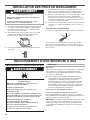
1. Pour éviter d'endommager le plancher, utiliser un grand
morceau de carton plat découpé dans l'emballage de
la sécheuse. Placer le carton sous tout le bord arrière
de la sécheuse. Voir l'illustration.
2. Saisir fermement la sécheuse par la caisse (et non pas
le panneau de commande). Incliner soigneusement
la sécheuse sur le carton. Voir l'illustration.
3. Inspecter les pieds de nivellement. Identier la marque
en losange.
4. Introduire manuellement les vis des pieds dans les trous.
Utiliser une clé à mollette pour visser les pieds jusqu'à ce
que le symbole de repérage (losange) ne soit plus visible.
5. Placer une cornière de carton sous chacun des angles arrière
de la sécheuse. Redresser la sécheuse. Faire glisser la
sécheuse sur les cornières jusqu'à ce qu'elle soit proche de
son emplacement nal. Laisser sufsamment d'espace pour
connecter le conduit d’évacuation.
6. Une fois que le raccordement est effectué et que la sécheuse
se trouve à son emplacement dénitif, ôter les cornières et
le carton.
Pour utilisation en maison mobile
Les sécheuses à gaz doivent être solidement xées au plancher.
Les installations en maison mobile nécessitent un ensemble
d'ancrage au sol pour installation en maison mobile. Pour le
processus de commande, consulter les “Instructions d'utilisation
de la sécheuse”.
INSTALLATION DES PIEDS DE NIVELLEMENT
La page est en cours de chargement...
La page est en cours de chargement...
La page est en cours de chargement...
La page est en cours de chargement...
La page est en cours de chargement...
La page est en cours de chargement...
La page est en cours de chargement...
La page est en cours de chargement...
-
 1
1
-
 2
2
-
 3
3
-
 4
4
-
 5
5
-
 6
6
-
 7
7
-
 8
8
-
 9
9
-
 10
10
-
 11
11
-
 12
12
-
 13
13
-
 14
14
-
 15
15
-
 16
16
-
 17
17
-
 18
18
-
 19
19
-
 20
20
-
 21
21
-
 22
22
-
 23
23
-
 24
24
-
 25
25
-
 26
26
-
 27
27
-
 28
28


Maytag EGD4400 Installation Instructions Manual
- Catégorie
- Sèche-linge
- Taper
- Installation Instructions Manual
- Ce manuel convient également à
dans d''autres langues
- English: Maytag EGD4400