SportsArt N957 Le manuel du propriétaire
- Catégorie
- Fitness, gymnastique
- Taper
- Le manuel du propriétaire

N957 OWNER’S MANUAL CONTENTS
1. INTRODUCTION ........................................................................... 2
2. SAFETY PRECAUTIONS ............................................................. 3
3. LIST OF PARTS ............................................................................. 4
4. ASSEMBLE THE PRODUCT ......................................................... 6
STEP 1 Install the Main Frame .................................................................. 6
STEP 2 Install the Leg Cushion ................................................................. 7
STEP 3 Install the Foot Covers ................................................................ 8
STEP 4 Install the Cap Nut ..................................................................... 9
STEP 5 Secure the Unit............................................................................. 10
STEP 6 Belt Tension Adjustment Instructions ........................................... 11
STEP 7 Minor Weight Stack Instructions ..................................................... 12
STEP 8 Unit Inspection ....................................................................... 13
5. OPERATE THE PRODUCT ............................................................. 14
OPERATION Safety Operating Area ........................................................... 14
OPERATION Exercising Instructions .......................................................... 15
OPERATION Operate the Product ............................................................. 16
6. MAINTENANCE ............................................................................... 18
MAINTENANCE Safety Precautions ......................................................... 18
MAINTENANCE Guide Rod Cleaning and Lubricating ................................. 19
MAINTENANCE Important Note ............................................................... 20
MAINTENANCE Schedule ..................................................................... 21
MAINTENANCE Task List ...................................................................... 22
MAINTENANCE Maintenance Log ............................................................ 23
7. CONSIGNES DE SÉCURITÉ IMPORTANTES ............................... 24
8. APPENDIXES ................................................................................. 25
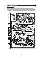
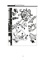
APPENDIXES Exploded Diagram ............................................................ 25

2
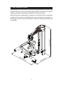
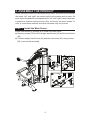
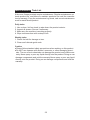
1. INTRODUCTION
Congratulations on the purchase of a high quality SportsArt product, the N957 Leg
Extension machine. Constructed of high quality materials and designed for years of
reliable performance, this product was made for full commercial use.
Before this product is assembled or operated, we recommend that you familiarize
yourself with this manual. Understanding the correct assembly and operation of
this product will help ensure that exercisers obtain their tness goals safely and
successfully.
1000mm(39.4 )
1295mm(51 )
1525mm(60.1 )

3
2. SAFETY PRECAUTIONS
This product was designed and built for optimum safety. However certain
precautions apply during the use of this product. Please note the following safety
precautions:
• Please read the entire manual before assembly and operation. Make
sure the product is installed and operated as instructed in this manual.
• Assemble and operate the product on a solid, level surface. Do not use
outdoors or near water, including pools and saunas.
• Check the product before every use. Make sure all parts are assembled,
and all fasteners are tightened. Do not use the product if it is disassembled
in any way.
• Wear proper workout clothing. Do not wear loose clothing. Do not wear
shoes with leather soles or high heels. Tie all long hair back. Do not go
barefoot on this product.
• Keep away from moving parts. Moving parts may or may not stop
immediately if an object becomes caught or impedes normal motion.
• Use this product only for its intended purpose as described in this manual.
• Be careful when mounting and dismounting the unit.
• Never operate this product if it has been damaged in any way. If it is
not working properly, or has been dropped or damaged, contact a service
technician for repairs.
• Do not use accessories or parts that are not specically recommended
by the manufacturer (SportsArt) . Such parts might cause injuries or cause
the unit to fail and void the warranty. We will not be responsible for any
safety issue that arises due to the misuse of accessories or parts. At the
same time, we will terminate the warranty terms of this equipment.
• This product is not intended for use by persons (including children 12
or younger) with reduced physical, sensory, or mental capabilities, or by
people who are otherwise decient in product knowledge or experience. If
such people use this product, they should be given training and be super-
vised at all times by someone responsible for their safety.
• Children ages 12 or younger should be supervised to ensure that they
do not play on or near the product.
• Maintenance and repair must be performed by trained service person-
nel only. Improper maintenance would not only damage the machine, but
also may present a danger to the exerciser.
• The user weight limit for this product is 227 kg (500 lb).
• Warning that any of the adjustment devices that could interfere with the
user’s movement should not be left projecting.
CAUTION: If you feel any pain or any abnormal sensations, STOP YOUR
WORKOUT and consult your physician immediately. Work within your
recommended exercise level. DO NOT work to exhaustion. Before beginning
any exercise program, you should consult with your doctor. It is recommended that
you undergo a complete physical examination.
Over exercise may result in serious injury or death. If you feel faint, stop exercising
immediately.
*NOTE: Each machine provides a different resistance ratio of weight stack.

4
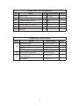
3. LIST OF PARTS
Assembly Parts
No. Name Qty. No. Name Qty.
A1 Weight Stack Frame 1 A7
Dual 80 Oval Foot Cover
B
1
A2 Leg Cushion 1 A8 118 Oval Foot Cover A 1
A3 Seat Frame 1 A9 118 Oval Foot Cover B 1
A4 Weight Stack Front Cover 1 A10 Ground Fixing Bracket 1
A5 Weight Stack Rear Cover 1 A11 U Clip 1
A6 Dual 80 Oval Foot Cover A 1

5
Components In the Hardware Kit
No. Name Qty. Specication Notes
10 Cover Cork 1 D23*t8.8
11 Push rivets 4
L-shaped Allen wrench 1 (M5)
L-shaped Allen wrench 1 (M6)
Double open-end wrench 1 (8*17)
Double open-end wrench 1 (17*23)
19 Cap nut
Components on the Product
No. Name Specication Notes
20
Hex head screw M10*P1.5*L30
Spring washer M10
Washer D16*d10.2*t1.0
Nylon hex nut M10*P1.5
21 Round head hex screw M8*P1.25*L20
22
Mushroom top Phillips screw
(heat treatment)
M5*0.8*L15 24
Flat washer D13*d6*t1.0

6
4. ASSEMBLE THE PRODUCT
Follow instructions below to assemble this product. Note that in this manual
the words “left” and “right” are used to refer to the product and its parts. As
such, these designations correspond to the “left” and “right” sides of a person
in position to exercise on this product. Also, for brevity, the word “screws” or
“nuts” is used where washers and other hardware may be involved.
STEP 1 Install the Main Frame
Follow instructions (a) through (b) to install the main frame.
(a) Remove screws (20) from the weight stack frame (A1) and the seat frame
(A3).
(b) Connect weight stack frame (A1) and the seat frame (A3) using screws
(20) to secure the assembly.

7
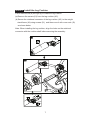
STEP 2 Install the Leg Cushion
Follow instructions (a) through (b) to install the leg cushion.
(a) Remove the screws (21) from the leg cushion (A2).
(b) Secure the rotational connector of the leg cushion (A2 ) to the weight
stack frame (A1) using screws (21), and then cover it with cover cork (10)
as shown below.
Note: When installing the leg cushion, align the holes on the rotational
connector with the cushion shaft before securing the assembly.

8
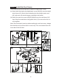
STEP 3 Install the Foot Covers
Follow instructions (a) through (b) to install the weight stack covers.
(a). Attach both front and rear weight stack covers (A4)(A5) onto the weight
stack frame (A1). (Note: before attaching the front weight stack cover
(A4), make sure the inside hanger is hooked to the frame).
(b). Attach the oval foot covers (A6)(A7)(A8)(A9) onto the seat frame (A2)
legs. Align the ends before using push rivets (11) to secure the foot co-
vers together.
Note: If the holes don’t match up while installing the oval foot covers, change
their direction and put them back in a new way. The cutout should face the
inner side of the foot tube.

9
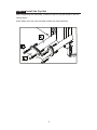
STEP 4 Install the Cap Nut
After completing the assembly, install the cap nut (19) as shown in the fol-
lowing figure.
Note: Make sure the cap nuts and screws are size-matching.

10
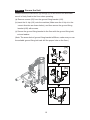
STEP 5 Secure the Unit
Please follow the instructions (a) through (c) to secure the unit and make
sure it is firmly fixed to the floor when operating.
(a) Remove screws (22) from the ground fixing bracket (A10).
(b) Insert the U clip (A11) onto the machine (Make sure the U clip is in the
correct direction as shown below), and then secure the ground fixing
bracket (A10) with screws.
(c) Secure the ground fixing bracket to the floor with the ground fixing bolt,
nut and washer.
(Note: The screw hole of ground fixing bracket is Ø9mm, make sure you use
the suitable ground fixing bolt and drill the proper hole on the floor.)
(b)
(a)
(c)

11
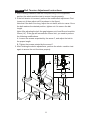
STEP 6 Belt Tension Adjustment Instructions
1. After finishing installation and the final positioning of the equipment,
perform the whole-machine-test to ensure it works properly.
2. If the belt tension is incorrect, perform the modification adjustment: First
loosen nut A then adjust nut B (as shown in the figure).
Note that if the belt is too long, adjust the nut down, and vice versa. Once
the belt reaches the desired position, tighten nut A to secure the belt
length.
Note: After adjusting the belt, the gap between nut A and B must be within
35mm(1.4”). If the gap still exceeds the 35mm limit, you need to perform
the following modifications:
A. Loosen the screws as pointed by the arrow-C, and adjust the belt to
the proper length.
B. Tighten the screws pointed by the arrow-C.
3. After finishing the above adjustments, perform the whole- machine -test
again to ensure the unit functions properly.

12
STEP 7 Minor Weight Stack Instructions
To adjust the minor weight stack, insert the upper pin to add 3.5Lbs/1.5kgs,
or the lower pin to add 6.5Lbs/3kgs. When the minor weights are not in use,
pull the pin to release the weight.

13
STEP 8 Unit Inspection
After completing the assembly or regular maintenance, please follow ins-
tructions (a) through (c) to inspect the unit. If the unit is disassembled or has
been damaged in any way, it might cause injuries or cause the unit to fail.
(a) Make sure the unit is steady and is on a level surface. If not, make ad-
justments according to the instructions “Secure the Unit” in this manual.
(b) Make sure all parts are assembled and all fasteners are tightened.
(c) Please follow operating instructions to test operation and make sure that
the equipment is working properly. (Please refer to “Operate the Product”
in this manual.)

14
5. OPERATION THE PRODUCT
This section includes operational instructions.
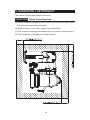
OPERATION Safety Operating Area
(a) Safety clearance required is shown below. Do not allow access for peo-
ple to near this area when operating.
(b) Noise emission under load is higher than without load.
(c) Over exercise or improper workout position may result in serious injury.
(d) This equipment is intended to build leg muscles.

15
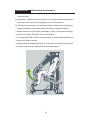
OPERATION Exercising Instructions
(a) Select the appropriate weight stacks according to your recommended
exercise level.
(b) Adjust the seatback and leg cushion to the most comfortable position
and make sure the knob is engaged to secure the position.
(c) Perform the exercise in a controlled manner. Inhale when pushing up
against resistance and exhale when returning to original position.
* Always workout at a level that is tolerable, to stay in the proper training
zone for your body. DO NOT work to exhaustion.
* Use equipment ONLY under the supervision of trained and qualified ins-
tructors for safety reasons.
* Please follow operating instructions on the product sticker to test opera-
tion and make sure the equipment is working properly.

16
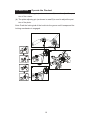
OPERATION Operate the Product
(a). The rotator adjusting pin (as shown in area A) is used to adjust the posi
tion of the rotator.
(b). The plate adjusting pin (as shown in area B) is used to adjust the posi
tion of the plate.
Note: Push the locking tab of the knob into the groove until it snaps and the
locking mechanism is engaged.

17
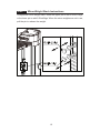
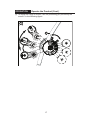
OPERATION Operate the Product (Cont.)
(c). To adjust the range of motion, use the positioning pin pointed by the
arrow-C in the following figure.

18
6. MAINTENANCE
This section covers maintenance topics and includes a maintenance
schedule, task list, and log.
MAINTENANCE Safety Precautions
● Please follow standard safety precautions when servicing on this pro-
duct.
● Do NOT use a damp towel to clean the product and do perform the fol-
lowing maintenances.
● Do NOT use cleaners with alcohol, ammonia, or other damaging chemi-
cals.The use of such chemicals can damage the product and void the
warranty. Never spray or pour any liquid directly onto the product. Doing
so can damage components and void the warranty.
● Use a clean, lint-free towel, dampened with a mixture of Simple Green®all-
purpose cleaner, to thoroughly clean the handlebar and the console.
● This product has moving parts that can be hazardous. Exercise caution-
when maintaining, operating, or moving this product.
● Do not use accessories or parts that are not specically recommend-
edby the manufacturer (SportsArt) . Such parts might cause injuries or
cause the unit to fail and void the warranty. We will not be responsible
for anysafety issue that arises due to the misuse of accessories or parts.
At the same time, we will terminate the warranty terms of this equipment.
● Maintenance and repair must be performed by trained service personnel
only. Improper maintenance would not only damage the machine, but
also may present a danger to the exerciser.
● Keep this product out of use until maintenance is completed.

19
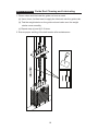
MAINTENANCE Guide Rod Cleaning and Lubricating
1. Please clean and lubricate the guide rod once a week.
(a) Use a clean, lint-free towel to apply the lubricant onto the guide rods.
(b) Test the weight stacks on the guide rod and make sure the weight
stacks move smoothly.
(c) Repeat step (a) and (b) 2-3 times.
2. Ensure proper settling of the belt tension after maintenance.

20
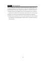
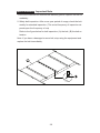
MAINTENANCE Important Note
1. Once the machine belt reaches the warranty period, replace the belt im
mediately.
2. Safety belt inspection: After a one-year period of usage, check the belt
weekly for standard inspection. (The actual frequency of inspection de
pends upon the frequency of use)
Refer to the figure below for belt inspection: (A) the belt, (B) the belt ex
tension.
Note: If you have a damaged or worn belt, stop using the equipment and
replace the belt immediately.
La page est en cours de chargement...
La page est en cours de chargement...
La page est en cours de chargement...
La page est en cours de chargement...
La page est en cours de chargement...
La page est en cours de chargement...
La page est en cours de chargement...
-
 1
1
-
 2
2
-
 3
3
-
 4
4
-
 5
5
-
 6
6
-
 7
7
-
 8
8
-
 9
9
-
 10
10
-
 11
11
-
 12
12
-
 13
13
-
 14
14
-
 15
15
-
 16
16
-
 17
17
-
 18
18
-
 19
19
-
 20
20
-
 21
21
-
 22
22
-
 23
23
-
 24
24
-
 25
25
-
 26
26
-
 27
27


SportsArt N957 Le manuel du propriétaire
- Catégorie
- Fitness, gymnastique
- Taper
- Le manuel du propriétaire
dans d''autres langues
- English: SportsArt N957 Owner's manual
Documents connexes
-
SportsArt N959 Le manuel du propriétaire
-
-
-
-
-
-
-
-
-