Parkside 710 B2 Manuel utilisateur
- Catégorie
- Outils électroportatifs
- Taper
- Manuel utilisateur

w
IAN 361816_2010
BENCH PILLAR DRILL PTBMOD 710 B2
CHAT
TISCHBOHRMASCHINE
Bedienungs- und Sicherheitshinweise
Originalbetriebsanleitung
DE
IE NI
BENCH PILLAR DRILL
Operating and Safety Instructions
Translation of Original Operating Manual
GB
PERCEUSE À COLONNE
Consignes d‘utilisation et de sécurité
Traduction des instructions d’origine
FR BE
TAFELBOORMACHINE
Bedienings- en veiligheidsinstructies
Vertaling van de originele handleiding
NL BE
BEIE NL

w
Klappen Sie vor dem Lesen die Seite mit den Abbildungen aus und machen Sie sich anschließend mit allen Funktionen des Gerätes vertraut.
DE AT CH
Before reading, unfold the page containing the illustrations and familiarise yourself with all functions of the device.
GB IE
Avant de lire le mode d‘emploi, ouvrez la page contenant les illustrations et familiarisez-vous ensuite avec toutes les fonctions de l‘appareil.
FR BE
Vouw vóór het lezen de pagina met de afbeeldingen open en maak u vertrouwd met alle functies van het apparaat.
NL BE
NI
GB / IE / NI Operating and Safety Instructions Page 01
FR / BE Consignes d‘utilisation et de sécurité Page 11
NL / BE Bedienings- en veiligheidsinstructies Pagina 22
DE / AT / CH Bedienungs- und Sicherheitshinweise Seite 33

1
2
78
10
11
12
14
17
6
5
4
3
2
1
15
1
1
2
2
3
3
4
4
5
5
6
6
7
7
8
8
9
9
10
10
11
11
12
12
13
13
14
14
15
15
16
16
A A
B B
C C
D D
E E
F F
G G
H H
I I
J J
K K
L L
4
1
1615
6
8
18
1
1
2
2
3
3
4
4
5
5
6
6
7
7
8
8
A A
B B
C C
D D
E E
F F
1
A2
Detail_Verschraubung_Fuß
Status Änderungen Datum Name
Gezeichn.
Kontroll.
Norm
Datum Name
18.04.2019 phg
1
6
A
3
C
22
B
8
21
7
21
9
16
13
7
2
23
3
23
13 G

7
16
17
2
16 15 17 215
5
E
22
D
F
6
c
l
o
s
e
/
t
i
g
h
t
e
n
o
p
e
n
/
r
e
l
e
a
s
e

98
10 11
2,5
27
9
19
20

1GB/IE/NI
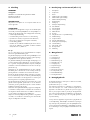
Table of contents: Page:
1. Explanation of the symbols on the device ......................................................................................................................................................... 2
2. Introduction ..........................................................................................................................................................................................................3
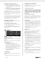
3. Device description (fig. 1-11) .............................................................................................................................................................................3
4. Scope of delivery ................................................................................................................................................................................................3
5. Proper use ............................................................................................................................................................................................................3
6. Safety instructions ................................................................................................................................................................................................4
7. Technical data ..................................................................................................................................................................................................... 6
8. Before commissioning ......................................................................................................................................................................................... 6
9. Assembly ..............................................................................................................................................................................................................6
10. Operation ............................................................................................................................................................................................................ 7
11. Transport ..............................................................................................................................................................................................................8
12. Cleaning and maintenance ................................................................................................................................................................................ 8
13. Storage ................................................................................................................................................................................................................8
14. Electrical connection ...........................................................................................................................................................................................8
15. Disposal and recycling .......................................................................................................................................................................................9
16. Troubleshooting ...................................................................................................................................................................................................9
17. Warranty certificate ..........................................................................................................................................................................................10
18. Declaration of conformity .................................................................................................................................................................................44

2GB/IE/NI
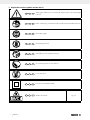
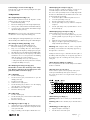
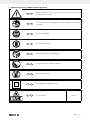
1. Explanation of the symbols on the device
GB IE NI Warning! Non-adherence poses a risk of death, danger of injury or the risk of damage
to the tool!
GB IE NI Before commissioning, read and observe the operating manual and safety instructions!
GB IE NI Wear safety goggles!
GB IE NI Wear hearing protection!
GB IE NI If dust builds up, wear respiratory protection!
GB IE NI Do not leave long hair loose. Use a hair net.
GB IE NI Do not wear gloves.
GB IE NI Protection class II (double shielded)
GB IE NI Attention! Laser beam fig. 8, 9

3GB/IE/NI
2. Introduction
MANUFACTURER:
scheppach
Fabrikation von Holzbearbeitungsmaschinen GmbH
Günzburger Straße 69
D-89335 Ichenhausen
DEAR CUSTOMER,
We hope your new tool brings you much enjoyment and suc-
cess.
NOTE:
In accordance with the applicable product liability laws, the
manufacturer of this device assumes no liability for damage to
the device or caused by the device arising from:
• Improper handling
• Failure to comply with the operating instructions.
• Repairs carried out by third parties, unauthorised specialists.
• Installing and replacing non-original spare parts,
• Improper use
• Failures of the electrical system in the event of the electri-
cal regulations and VDE provisions 0100, DIN 57113 /
VDE0113 not being observed.
Note:
Read the whole text of the operating manual before assembly
and commissioning.
This operating manual should help you to familiarise yourself
with your device and to use it for its intended purpose.
The operating manual includes important instructions for safe,
proper and economic operation of the device, for avoiding
danger, for minimising repair costs and downtimes, and for
increasing the reliability and extending the service life of the
device.
In addition to the safety instructions in this operating manual,
you must also observe the regulations applicable to the opera-
tion of the device in your country.
Keep the operating manual at the device, in a plastic sleeve,
protected from dirt and moisture. They must be read and care-
fully observed by all operating personnel before starting the
work.
The device may only be used by personnel who have been
trained to use it and who have been instructed with respect to
the associated hazards. The required minimum age must be
observed.
In addition to the safety instructions in this operating manual
and the separate regulations of your country, the generally
recognised technical rules relating to the operation of such ma-
chines must also be observed.
We accept no liability for accidents or damage that occur due
to a failure to observe this manual and the safety instructions.
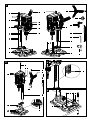
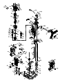
3. Device description (fig. 1-11)
1. Base plate
2. Quick clamp
3. Column
4. Toothed rack for height adjustment
5. Clamping lever for height adjustment
6. Clamping lever for depth stop
7. Depth stop
8. Handle
9. Pointer, depth stop
10. Off switch
11. On switch
12. Speed control
13. Spacer
14. Chuck
15. Wing screws for parallel stop
16. Parallel stop
17. Quick-clamp screw
18. Laser ON/OFF switch
19. Phillips screw (pointer)
20. Scale
21. Allen key, 4mm
22. Chuck key
23. Marking
4. Scope of delivery
• 1 Drilling machine
• 1 Quick clamp (2)
• 1 Base plate (1)
• 1 Parallel stop (16)
• 1 Spacer (13)
• 1 handle (8)
• 1 Depth stop (7)
• 1 Clamping lever (6)
• 1 Allen key, 4mm (21)
• 1 Chuck key (22)
• 1 Operating manual
• 1 Assembly material
5. Proper use
The bench drill is designed for drilling in metal, wood, plastic
and tiles.
Chuck clamping range: 1.5 - 13mm.
The device is only intended to be used for DIY purposes. It
was not designed for continuous commercial use. The device is
not intended for use by people under the age of 16. Children
under the age of 16 may only use the device when supervised.
The manufacturer is not liable for damage caused by improper
use or incorrect operation.
Please observe that our equipment was not designed with the
intention of use for commercial or industrial purposes. We as-
sume no guarantee if the equipment is used in commercial or
industrial applications, or for equivalent work.

4GB/IE/NI
6. Safety instructions
General power tool safety warnings
m WARNING! Read all safety warnings, instruc-
tions, illustrations and specifications provided with
this power tool.
Failure to follow all instructions listed below may result in elec-
tric shock, fire and/or serious injury.
Save all warnings and instructions for future refer-
ence.
The term “power tool” in the warnings refers to your mains-
operated (corded) power tool or battery-operated (cordless)
power tool.
Work area safety
a) Keep work area clean and well lit.
Cluttered or dark areas invite accidents.
b) Do not operate power tools in explosive atmos-
pheres, such as in the presence of flammable liq-
uids, gases or dust.
Power tools create sparks which may ignite the dust or
fumes.
c) Keep children and bystanders away while operat-
ing a power tool.
Distractions can cause you to lose control.
Electrical safety
a) Power tool plugs must match the outlet.
Never modify the plug in any way. Do not use any adapt-
er plugs with earthed (grounded) power tools. Unmodi-
fied plugs and matching outlets will reduce risk of electric
shock.
b) Avoid body contact with earthed or grounded
surfaces, such as pipes, radiators, ranges and
refrigerators. There is an increased risk of elec-
tric shock if your body is earthed or grounded.
c) Do not expose power tools to rain or wet con-
ditions.
Water entering a power tool will increase the risk of elec-
tric shock.
b) Do not abuse the cord. Never use the cord for
carrying, pulling or unplugging the power
tool.
Keep cord away from heat, oil, sharp edges or moving
parts. Damaged or entangled cords increase the risk of
electric shock.
e) When operating a power tool outdoors, use
an extension cord suitable for outdoor use.
Use of a cord suitable for outdoor use reduces the risk of
electric shock.
f) If operating a power tool in a damp location
is unavoidable, use a residual current device
(RCD) protected supply.
Use of an RCD reduces the risk of electric shock.
Personal safety
a) Stay alert, watch what you are doing and use
common sense when operating a power tool.
Do not use a power tool while you are tired or
under the influence of drugs, alcohol or medi-
cation.
A moment of inattention while operating power tools may
result in serious personal injury.
b) Use personal protective equipment. Always
wear eye protection.
Protective equipment such as a dust mask, non-skid safety
shoes, hard hat or hearing protection used for appropri-
ate conditions will reduce personal injuries.
c) Prevent unintentional starting. Ensure the
switch is in the off-position before connecting
to power source and/or battery pack, picking
up or carrying the tool.
Carrying power tools with your finger on the switch or
energising power tools that have the switch on invites ac-
cidents.
d) Remove any adjusting key or wrench before
turning the power tool on.
A wrench or a key left attached to a rotating part of the
power tool may result in personal injury.
e) Do not overreach. Keep proper footing and
balance at all times.
This enables better control of the power tool in unexpect-
ed situations.
f) Dress properly. Do not wear loose clothing or
jewellery. Keep your hair and clothing away
from moving parts. Loose clothes, jewellery or long
hair can be caught in moving parts.
g) If devices are provided for the connection of
dust extraction and collection facilities, ensure
these are connected and properly used.
Use of dust collection can reduce dust-related hazards.
h) Do not let familiarity gained from frequent use
of tools allow you to become complacent and
ignore tool safety principles. A careless action can
cause severe injury within a fraction of a second.
Power tool use and care
a) Do not force the power tool. Use the correct
power tool for your application.
The correct power tool will do the job better and safer at
the rate for which it was designed.
b) Do not use the power tool if the switch does
not turn it on and off. Any power tool that can-
not be controlled with the switch is dangerous
and must be repaired.
c) Disconnect the plug from the power source
and/or remove the battery pack, if detach-
able, from the power tool before making any
adjustments, changing accessories, or storing
power tools.
Such preventive safety measures reduce the risk of start-
ing the power tool accidentally.

5GB/IE/NI
d) Store idle power tools out of the reach of chil-
dren and do not allow persons unfamiliar with
the power tool or these instructions to operate
the power tool.
Power tools are dangerous in the hands of untrained users.
e) Maintain power tools and accessories.
Check for misalignment or binding of moving parts, break-
age of parts and any other condition that may affect the
power tool’s operation. If damaged, have the power tool
repaired before use. Many accidents are caused by poor-
ly maintained power tools.
f) Keep cutting tools sharp and clean. Properly
maintained cutting tools with sharp cutting
edges are less likely to bind and are easier to
control.
g) Use the power tool, accessories and tool bits
etc. in accordance with these instructions, tak-
ing into account the working conditions and
the work to be performed.
Use of the power tool for operations different from those
intended could result in a hazardous situation.
h) Keep handles and grasping surfaces dry,
clean and free from oil and grease. Slippery han-
dles and grasping surfaces do not allow for safe handling
and control of the tool in unexpected situations.
Service
a) Have your power tool serviced by a qualified
repair person using only identical replacement
parts. This will ensure that the safety of the power tool
is maintained.
Drill safety warnings
a) The drill must be secured. An incorrectly secured drill
can move or topple and this can result in injuries.
b) The workpiece must be clamped or fastened
to the workpiece support. Do not drill into
workpieces that are too small to be securely
clamped. Holding the workpiece by hand can lead to
injuries.
c) Do not wear gloves. Gloves can be caught by rotating
parts or drilling debris and thus cause injuries.
d) Keep your hands away from the drilling area
whilst the electrical tool is running. Contact with
rotating parts or drilling debris can cause injuries.
e) The drill must be turning before it makes con-
tact with the workpiece. Otherwise, the drill bit can
catch in the workpiece and this can result in an unexpected
movement of the workpiece and cause injuries.
f) If the drill becomes jammed, stop pressing
downwards and switch the electrical tool off.
Investigate and rectify the cause of the jam-
ming. Jamming can result in an unexpected movement of
the workpiece and can result in serious injuries.
g) Avoid long pieces of drill swarf by interrupting
the downward pressure at regular intervals.
Sharp metal swarf can become tangled and lead to in-
juries.
h) Never remove drilling debris from the drilling
area whilst the electrical tool is running. To
remove swarf, move the drill away from the
workpiece, switch off the electrical tool and
wait until the drill has come to a standstill. Use
an aid such as a brush or a hook to remove the
swarf. Contact with rotating parts or drilling debris can
cause injuries.
i) The permissible rotational speed for drill bits
with a rated speed must be at least as high as
the highest speed cited on the electrical tool. Ac-
cessories that rotate faster than permitted can break and
fly off at high speed.
Attention: Laser radiation
Do not look into the beam
Laser class 2
Protect yourself and you environment from acci-
dents using suitable precautionary measures
• Do not look directly into the laser beam with unprotected
eyes.
• Never look into the path of the beam.
• Never point the laser beam towards reflecting surfaces and
persons or animals. Even a laser beam with a low output can
cause damage to the eyes.
• Caution - methods other than those specified here can result
in dangerous radiation exposure.
• Never open the laser module. Unexpected exposure to the
beam can occur.
• The laser may not be replaced with a different type of laser.
• Repairs of the laser may only be carried out by the laser
manufacturer or an authorised representative.
• Labelling and placement of warning stickers, see fig. 8 and
9.
m WARNING! This electric tool generates an electromag-
netic field during operation. This field can impair active or
passive medical implants under certain conditions. In order to
prevent the risk of serious or deadly injuries, we recommend
that persons with medical implants consult with their physician
and the manufacturer of the medical implant prior to operating
the electric tool.
Residual risks
Even when this electric tool is operated properly,
residual risks still remain. The following hazards
may arise in connection with the design and con-
struction of this electric tool:
• Lung damage if suitable dust protection mask is not worn.
• Hearing damage if suitable hearing protection is not worn.
• Damage to health resulting from hand/arm vibration if the
device is used over an extended period of time or if it is not
properly operated and maintained.

6GB/IE/NI
7. Technical data
AC motor....................................................220 - 240 V~ 50 Hz
Nominal power S1 ......................................................710 Watt
Operating mode ...............................................S2 5min* 900W
Idle speed n0 ....................................................500 - 2600 min-1
Drill chuck clamping range ..................................... 1.5 - 13mm.
Max. drill stroke.................................................................70 mm
Size of base plate ...............................................320 x 305 mm
Distance chuck to bottom plate ..................................... 280 mm
Weight approx. ..................................................................8,3 kg
Protection class ...................................................................II /
Laser class ...................................................................................2
Laser wavelength ............................................................. 650 nm
Laser power .....................................................................< 1 mW
* After an uninterrupted operating period of 5 minutes, the de-
vice should be allowed to rest until its temperature has dropped
to within 2K (2°C) of room temperature.
The workpiece must have a minimum height of
3mm and a minimum width of 45mm.
Make sure that the workpiece is always secured
with the clamping device.
Overhanging workpieces may have to be support-
ed laterally by additional supports.
Noise
The noise levels have been determined in accordance with EN
62841.
Sound pressure level LpA ............................................ 89,6 dB(A)
Uncertainty KpA ......................................................................3 dB
Sound power level LWA ............................................ 102,6 dB(A)
Uncertainty KWA .....................................................................3 dB
Wear hearing protection.
Excessive noise can result in a loss of hearing.
The above-mentioned noise emission values were measured in
accordance with a standardised test procedure and can be
used to compare one power tool with another.
The specified device emissions values can also be used for an
initial estimation of the load.
Warning:
• The noise emission values can vary from the specified values
during the actual use of the electric tool, depending on the
type and the manner in which the electric tool is used, and in
particular the type of workpiece being processed.
• Try to keep the stress as low as possible. For example: Limit work-
ing time. In doing so, all parts of the operating cycle must be taken
into account (such as times in which the electric tool is switched off
or times in which it is switched on, but is not running under a load).
8. Before commissioning
• Open the packaging and carefully remove the device.
• Remove the packaging material as well as the packaging
and transport bracing (if available).
• Check whether the scope of delivery is complete.
• Check the device and accessory parts for transport damage.
• If possible, keep the packaging until the expiry of the war-
ranty period.
ATTENTION
The device and the packaging are not children‘s
toys! Do not let children play with plastic bags,
films or small parts! There is a danger of choking
or suffocating!
Before connecting the machine, make certain that the data on
the type plate matches with the mains power data.
• Check the device for transport damage. Immediately report
any damage to the transport company that delivered the
electrical tool.
• Long supply cables (extension cable) should be avoided.
• Do not operate the electrical tool in damp or wet areas.
• Operate the electrical tool only in suitable areas (well ven-
tilated).
9. Assembly
m Attention!
Always make sure the device is fully assembled before com-
missioning!
m Before connecting the machine to the mains power, make certain
that the data on the type plate matches with the mains power data.
m Warning! Always pull out the mains plug before carrying
out adjustments on the device.
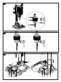
9.1 Assembling the base plate and column (fig. 2)
1. Slide the quick clamp (2) over the column (3).
2. Set the column (3) into the base plate (1) such that the
guide pins on the bottom end of the column (3) engage
with the groove in the mount on the base plate (1).
3. Tighten the pre-assembled fastening screws (A) on the
rear of the base plate (1) with the Allen key (21).
9.2 Fitting the parallel stop (fig. 4)
1. Slide the parallel stop (16) into the grooves in the base
plate (1).
2. Ensure that the sliding blocks underneath the wing screws
of the parallel stop (15) are properly engaged in the
grooves of the base plate.
3. Move the parallel stop (16) to the desired position and
tighten the wing screws of the parallel stop (15) firmly.
9.3 Assembling the handle (fig. 2)
1. Remove the pre-assembled fastening screw (B).
2. Ensure that the spacer (13) is seated correctly.
3. Slide the handle (8) onto the retainer (G) as shown in fig. 2.
4. Place the nut (C) in the recess in the handle (8) and tight-
en the fixing screw (B).
9.4 Fitting the depth stop (fig. 2)
1. Insert the depth stop (7) from above into the recess in
the housing.
2. Assemble the clamping lever for depth stop (6) as shown
in fig. 2.

7GB/IE/NI
9.5 Fastening to a work surface (fig. 4)
Fasten the device to the work surface by bolting the base plate
(1) to the work surface.
10. Operation
10.1 Height adjustment (fig. 2, 3)
The position of the machine head can be adjusted to suit the
workpiece height or the workpiece length.
1. Hold the handle (8) firmly.
2. Release the clamping lever for the height adjustment (5).
3. Set the position of the machine head with the handle (8).
4. Secure the position of the machine head with the height
adjustment clamping lever (5).
Attention! In the lowest position of the machine head make
sure that it does not move beyond the marking (23).
Use the clamping lever for height adjustment (5) to secure the ma-
chine head in this position. Otherwise, the guide could be damaged.
10.2 Setting the drilling depth (fig. 1, 11)
The drilling depth can be set with the depth stop (7).
1. Release the clamping lever on the depth stop (6).
2. Carry out a test drilling. Once the desired depth is
reached, tighten the depth stop clamping lever (6) again.
3. The depth stop (7) is now locked in the desired drilling depth.
4. Then check the position of the depth stop. If the indicat-
ed dimension does not correspond to the actual drilling
depth, the pointer (9) can be readjusted.
• Loosen the Phillips screw (19) on the pointer (9).
• Set the pointer (9) to the correct position to the scale (20).
• Re-tighten the Phillips screw (19).
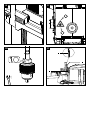
10.3 Clamping/releasing tools (fig. 5, 6)
Caution! Do not leave the chuck key in the clamp
hole. Doing so will cause the chuck key to be cata-
pulted out, which could cause injury.
10.3.1 Clamping
1. Insert the chuck key (22).
2. Turn the chuck key (22) counterclockwise to open the
clamping sleeve (D).
3. Insert the insert tool (E).
4. Hold the insert tool (E) in place.
5. Turn the chuck key (22) clockwise to close the clamping
sleeve (D) and to secure the insert tool.
6. Check that the insert tool (E) is tight.
7. Pull out the chuck key (22).
10.3.2 Releasing
1. Insert the chuck key (22).
2. Turn the chuck key (22) counterclockwise until the drill bit
(E) can be removed.
3. Pull out the chuck key (22).
10.4 Aligning workpieces (fig. 1)
1. Switch on the laser cross using the On/off switch laser (18).
2. The intersection of the two laser lines exactly indicates the
centre point of the drill.
3. Align your marking on the workpiece with the laser cross.
10.5 Clamping the workpiece (fig. 7)
It must be possible to clamp the workpiece securely. Do not
work with workpieces that cannot be clamped securely.
The cut-out of the quick clamp must be centrally aligned with
the hole to be drilled. Otherwise, the drill bit or the chuck could
be obstructed by the quick clamp.
1. Position the workpiece with the help of the laser cross.
2. Loosen the quick clamp screw (17).
3. Place the quick clamp (2) on the workpiece.
4. Turn the quick clamp screw (17) clockwise to clamp the
workpiece.
5. Turn the quick clamp screw (17) anticlockwise to loosen
the quick clamp (2).
10.6 Clamping larger workpieces (fig. 7)
Use the parallel stop (16) for larger workpieces:
1. Loosen the wing screws for the parallel stop (15) and
insert the parallel stop (16) into the grooves of the base
plate.
2. Tighten the wing screws for the parallel stop (15).
3. Align your workpiece against the parallel stop (16) and
clamp it with the quick clamp (2).
Warning! With workpieces that are wider or longer than
the tabletop, ensure that these are adequately supported, e.g.
through trestles or saw horses.
Workpieces that are longer or wider than the base plate of
the tabletop drill can tip if they are not properly supported. If
the workpiece tips, this can damage the chuck guard or the
cutting tool.
10.7 Setting the drilling speed (fig. 1)
The correct speed must be set to suit the workpiece to be drilled
and the tool diameter.
10.7.1 Electronic speed control
Use the electronic speed control to steplessly set the speed:
Set the speed with the help of the speed control (12).
The current speed can be seen using the mark on the speed
control (12).
10.8 Switching on/off (fig. 1)
Switching on: Press the on switch (11) to switch the device
on.
Switching off: Press the off switch (10) to switch the device
off.
10.9 Drilling procedure (fig. 1, 7)
1. Align the workpiece and clamp it.
2. Start the device and set the speed.

8GB/IE/NI
3. For drilling, move the handle (8) with uniform feed until
the desired drilling depth is reached. When drilling into
metal, interrupt the downward pressure briefly to break
the swarf.
4. After reaching the drilling depth, return the handle (8) to
the starting position.
5. Switch the device off.
11. Transport
m Warning! Unplug the mains plug prior to transport!
• To transport the device hold it by the base plate (1).
12. Cleaning and maintenance
m Warning! Pull out the mains plug before carrying out any
adjustments, maintenance or repair work!
12. 1 General maintenance tasks
m Have tasks that are not described in this operat-
ing manual performed by a specialist workshop.
Use only original parts. Let the device cool down
before all maintenance and cleaning tasks.
m There is a risk of burn!
Before using the device each time, check the device for obvi-
ous defects such as worn or damaged parts, correct seating of
screws or other parts. Replace damaged parts.
12.2 Cleaning
Do not use cleaning agents or solvents. Chemical substances
could damage the plastic parts of the device. Never clean the
device under running water.
• Clean the device thoroughly after each use.
• Clean the ventilation holes and the surface of the device with
a soft brush or cloth.
• Remove swarf, dust and dirt with a vacuum cleaner if neces-
sary.
• Lubricate the moving parts regularly.
12.3 Maintenance
The device has no parts that require maintenance.
12.4 Replacing the chuck (fig. 1, 5, 10)
m Warning! Pull out the mains plug!
Tools required (not included in the scope of delivery):
1x open-ended wrench 27mm
• Remove the insert tool as described in 10.3.2.
• Tighten the clamping sleeve (D) firmly by turning the chuck
key (22) clockwise.
• Hold the chuck (14) with one hand while using the open-
ended wrench (27mm) to lower the nut (F) clockwise.
• Once the chuck (14) is loosened from the shaft seat, it can
be removed.
• Fasten the new chuck in reverse order.
When replacing the chuck, use only chucks approved by the
manufacturer.
Order number: 390 6814 001
12.5 Service information
With this product, it is necessary to note that the following parts
are subject to natural or usage-related wear, or that the follow-
ing parts are required as consumables.
Wear parts*: Carbon brushes, drill bit
* may not be included in the scope of supply!
13. Storage
Store the device and its accessories in a dark, dry and frost-
free place that is inaccessible to children. The optimum storage
temperature lies between 5 and 30 °C.
Store the electric tool in its original packaging.
Cover the electric tool to protect it from dust or moisture.
Store the operating manual with the electric tool.
14. Electrical connection
The electrical motor installed is connected and
ready for operation. The connection complies with
the applicable VDE and DIN provisions. The cus-
tomer‘s mains connection as well as the extension
cable used must also comply with these regula-
tions.
14.1 Important information
In the event of overloading, the motor will switch itself off. After
a cool-down period (time varies) the motor can be switched
back on again.
14.2 Faulty power supply cables
The insulation on electrical connection cables is often dam-
aged.
This may have the following causes:
• Pressure points, where connection cables are passed through
windows or doors.
• Kinks where the connection cable has been improperly fas-
tened or routed.
• Places where the connection cables have been cut due to
being driven over.
• Insulation damage due to being ripped out of the wall outlet.
• Cracks due to the insulation ageing.
Such damaged electrical connection cables must not be used
and are life-threatening due to the insulation damage.
Check the electrical connection cables for damage regularly.
Ensure that the connection cables are disconnected from elec-
trical power when checking for damage.
Electrical connection cables must comply with the applicable
VDE and DIN provisions. Only use connection cables with the
marking H05VV-F.
The printing of the type designation on the connection cable
is mandatory.
If it is necessary to replace the connection cable, this must
be done by the manufacturer or their representative to avoid
safety hazards.
14.3 AC motor
The mains voltage must be 220 - 240 V~ 50Hz.
• Extension cables up to 25 m long must have a cross-section
of 1.5 mm2.

9GB/IE/NI
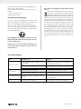
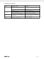
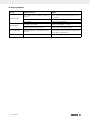
16. Troubleshooting
Fault Possible cause Remedy
Device does not start
Motor, cable or plug defective, building circuit
breaker tripped
Check power outlet, mains connection cable, mains
plug. Have repair carried out by electrical specialist.
Check building circuit breakers.
On/off switch (11/10) defective Repair by customer service department
Motor defective Repair by customer service department
Heavy vibrations Base plate (1) not fastened in place. Secure machine to a work bench or similar
Drill bit not clamped centrally Check drill bit in chuck (14)
Motor overheats easily Overloading of the motor, insufficient cooling of
the motor.
Avoid overloading the motor while drilling,
remove dust from the motor in order to ensure optimal
cooling of the motor.
Motor makes excessive
noise Coils damaged, motor defective. Have checked by customer service department
Connections and repair work on the electrical equipment may
only be carried out by electricians.
Please provide the following information in the event of any
enquiries:
• Type of current for the motor
• Engine data - type plate
15. Disposal and recycling
The device is supplied in packaging to avoid transport dam-
ages. This packaging is raw material and can thus be used
again or can be reintegrated into the raw material cycle.
The device and its accessories are made of different materi-
als, such as metals and plastics. Take defective components to
special waste disposal sites. Check with your specialist dealer
or municipal administration!
The packaging is wholly composed of environmen-
tally-friendly materials that can be disposed of at
a local recycling centre.
Contact your local refuse disposal authority for
more details of how to dispose of your worn-out
electrical devices.
Do not throw old equipment away with household
waste!
This symbol indicates that this product must not be dis-
posed of in household waste as per Waste Electrical
and Electronic Equipment directive (2012/19/EU) and
national laws. This product must be handed over at the
intended collection point. This can be done, for example, by
returning it when purchasing a similar product or delivering it to
an authorised collection point for the recycling of old electrical
and electronic devices. Improper handling of old devices can
have negative effects on the environment and on human health
due to potential hazardous materials which are often con-
tained in old electrical and electronic devices. By disposing of
this product properly, you are also contributing to the effective
use of natural resources. Information about collection points for
old devices can be found at your municipal authority, the local
disposal provider, an authorised location for the disposal of old
electrical and electronic devices or your waste collection ser-
vice.

10 GB/IE/NI
17. Warranty certificate
Dear Customer,
All of our products undergo strict quality checks to ensure that they reach you in perfect condition. In the unlikely event that your device
develops a fault, please contact our service department at the address shown on this guarantee card. Of course, if you would prefer to
call us then we are also happy to offer our assistance under the service number printed below. Please note the following terms under which
guarantee claims can be made:
• These guarantee terms cover additional guarantee rights and do not affect your statutory warranty rights. We do not charge you for
this guarantee.
• Our guarantee only covers problems caused by material or manufacturing defects, and it is restricted to the rectification of these de-
fects or replacement of the device. Please note that our devices have not been designed for use in commercial, trade or industrial ap-
plications. Consequently, the guarantee is invalidated if the equipment is used in commercial, trade or industrial applications or for
other equivalent activities. The following are also excluded from our guarantee: compensation for transport damage, damage caused
by failure to comply with the installation/assembly instructions or damage caused by unprofessional installation, failure to comply with
the operating instructions (e.g. connection to the wrong mains voltage or current type), misuse or inappropriate use (such as overload-
ing of the device or use of non-approved tools or accessories), failure to comply with the maintenance and safety regulations, ingress
of foreign bodies into the device (e.g. sand, stones or dust), effects of force or external influences (e.g. damage caused by the device
being dropped) and normal wear resulting from proper operation of the device.
The guarantee is rendered null and void if any attempt is made to tamper with the device.
• The guarantee is valid for a period of 3 years starting from the purchase date of the device. Guarantee claims should be submitted
before the end of the guarantee period within two weeks of the defect being noticed. No guarantee claims will be accepted after the
end of the guarantee period. The original guarantee period remains applicable to the device even if repairs are carried out or parts
are replaced. In such cases, the work performed or parts fitted will not result in an extension of the guarantee period, and no new
guarantee will become active for the work performed or parts fitted. This also applies when an on-site service is used.
• In order to assert your guarantee claim, please contact the service partner shown below. If the complaint is within the guarantee pe-
riod, we will provide you with a return slip, with which you can return your defective device free of charge to us. It would help us if you
could describe the nature of the problem in as much detail as possible. If the defect is covered by our guarantee then your device will
either be repaired immediately and returned to you, or we will send you a new device.
Of course, we are also happy offer a chargeable repair service for any defects which are not covered by the scope of this guarantee or for
units which are no longer covered. To take advantage of this service, please send the device to our service address.
Service-Hotline (GB/IE/NI):
+800 4003 4003
(0,00 EUR/Min.)
Service-Email (GB):
service.GB@scheppach.com
Service-Email (IE/NI):
Service Address (GB/IE/NI):
Forest Park & Garden
Coed Court, Taffsmead Road
Treforest, Ind. Estate, Pontypridd CF375SW
At www.lidl-service.com you can download this and many more manuals, product videos plus installation
software.
The QR code takes you directly to the Lidl service page (www.lidl-service.com) and you can open your oper-
ating manual by entering the article number (IAN) 361816_2010.

11FR/BE
Table des matières: Page:
1. Explication des symboles sur l’appareil ...........................................................................................................................................................12
2. Introduction ........................................................................................................................................................................................................13
3. Description de l’appareil (ill. 1-11) ..................................................................................................................................................................13
4. Fournitures .........................................................................................................................................................................................................13
5. Utilisation conforme ..........................................................................................................................................................................................13
6. Consignes de sécurité .......................................................................................................................................................................................14
7. Caractéristiques techniques ..............................................................................................................................................................................16
8. Avant la mise en service ...................................................................................................................................................................................16
9. Montage ............................................................................................................................................................................................................16
10. Commande ........................................................................................................................................................................................................17
11. Transport ............................................................................................................................................................................................................18
12. Nettoyage et maintenance ...............................................................................................................................................................................18
13. Stockage ............................................................................................................................................................................................................19
14. Raccordement électrique ..................................................................................................................................................................................19
15. Élimination et recyclage ....................................................................................................................................................................................19
16. Dépannage .......................................................................................................................................................................................................20
17. Certificat de garantie ........................................................................................................................................................................................21
18. Déclaration de conformité ................................................................................................................................................................................44

12 FR/BE
1. Explication des symboles sur l’appareil
FR BE Avertissement! En cas de non-respect des instructions, risque de blessures graves, voire
mortelles, ou d’endommagement de l‘outil!
FR BE Lire la notice d’utilisation et observer les consignes de sécurité avant de procéder à la
mise en service!
FR BE Porter des lunettes de protection!
FR BE Porter une protection auditive!
FR BE En cas de génération de poussières, porter une protection respiratoire!
FR BE Ne portez pas vos cheveux longs détachés. Utilisez un filet.
FR BE Ne pas porter de protection des mains.
FR BE Classe de protection II (double isolation)
FR BE Attention! Rayonnement laser ill. 8, 9

13FR/BE
2. Introduction
FABRICANT:
scheppach
Fabrikation von Holzbearbeitungsmaschinen GmbH
Günzburger Straße 69
D-89335 Ichenhausen
CHER CLIENT,
Nous espérons que votre nouvelle machine vous apportera
satisfaction et de bons résultats.
REMARQUE:
Conformément à la loi en vigueur sur la responsabilité du fait
des produits, le fabricant de cet appareil n‘est pas responsable
des dommages survenus ou générés sur l‘appareil en cas de:
• Manipulation incorrecte,
• Inobservation de la notice d‘utilisation,
• Réparations effectuées par des tiers ou des spécialistes non
autorisés,
• Montage et remplacement des pièces de rechange non ori-
ginales,
• Utilisation non conforme,
• Pannes de l’installation électrique, en cas de non-respect des
prescriptions électriques et des dispositions de la VDE 0100,
DIN 57113 / VDE0113.
Attention:
Lisez l‘ensemble du texte de la notice d‘utilisation avant le mon-
tage et la mise en service.
La présente notice d’utilisation a pour objectif de vous fami-
liariser avec votre appareil et d‘en exploiter les possibilités
d‘emploi conforme.
La notice d‘utilisation contient des remarques importantes sur
la manière de travailler en toute sécurité, réglementairement
et économiquement avec l’appareil et sur la façon d‘éviter les
dangers, d’économiser les coûts de réparation, de réduire les
périodes d‘arrêt et d’augmenter la fiabilité et la durée de vie
de l‘appareil.
Outre les dispositions de sécurité figurant dans cette notice
d‘utilisation, vous devez absolument observer les prescriptions
concernant le fonctionnement de l‘appareil en vigueur dans
votre pays.
Conservez la notice d‘utilisation dans une pochette en plas-
tique à l‘abri de la poussière et de l‘humidité près de l‘appareil.
Chaque opérateur doit l‘avoir lue avant le début des travaux et
doit la respecter minutieusement.
Seules des personnes formées à l‘utilisation de l‘appareil et in-
formées des dangers associés sont autorisées à travailler avec
l’appareil. Respecter la limite d‘âge minimum requis.
Outre les consignes de sécurité reprises dans la présente notice
d‘utilisation et les prescriptions particulières en vigueur dans
votre pays, respecter également les règles techniques géné-
rales concernant l‘utilisation des machines similaires.
Nous déclinons toute responsabilité concernant les accidents
ou dommages qui surviendraient en raison d‘un non-respect de
cette notice et des consignes de sécurité.
3. Description de l’appareil (ill. 1-11)
1. Socle
2. Tendeur rapide
3. Colonne
4. Crémaillère de réglage de la hauteur
5. Levier de blocage de la hauteur
6. Levier de blocage de la butée de profondeur
7. Butée de profondeur
8. Poignée
9. Pointeur de butée de profondeur
10. Interrupteur Off
11. Interrupteur On
12. Régulateur de vitesse
13. Entretoise
14. Mandrin de perceuse
15. Vis papillon de la butée parallèle
16. Butée parallèle
17. Vis de serrage rapide
18. Interrupteur On/Off de laser
19. Vis cruciforme (pointeur)
20. Échelle
21. Clé Allen, 4mm
22. Clé de mandrin de perceuse
23. Marquage
4. Fournitures
• 1 Perceuse à colonne
• 1 Dispositif de serrage rapide (2)
• 1 Plaque de base (1)
• 1 Butée parallèle (16)
• 1 Entretoise (13)
• 1 Poignée (8)
• 1 Butée de profondeur (7)
• 1 Levier de blocage (6)
• 1 Clé Allen, 4mm (21)
• 1 Clé de mandrin de perceuse (22)
• 1 Manuel d‘utilisation
• 1 Matériel de montage
5. Utilisation conforme
La perceuse à colonne d‘établi est conçue pour le perçage
dans le métal, le bois, le plastique et le carrelage.
Capacité de serrage du mandrin: de 1,5 à 13mm.
L‘appareil est destiné à être utilisé pour le bricolage. Il n‘a pas
été conçu pour une utilisation commerciale continue. L‘appa-
reil n’est pas destiné à être utilisé par des jeunes de moins de
16ans. Les jeunes de plus de 16ans ne peuvent utiliser l‘appa-
reil que sous surveillance. Le fabricant décline toute responsa-
bilité quant aux dommages dus à une utilisation non conforme
ou à une fausse manipulation.
Remarque: conformément aux dispositions, nos appareils n‘ont
pas été conçus pour une utilisation commerciale, artisanale ou
industrielle. Nous déclinons toute responsabilité si l‘appareil
est utilisé dans des exploitations commerciales, artisanales ou
industrielles, ou dans le cadre d‘activités comparables.

14 FR/BE
6. Consignes de sécurité
Consignes de sécurité générales pour les outils
électriques
m AVERTISSEMENT! Lisez toutes les consignes de
sécurité, instructions, illustrations et caractéris-
tiques techniques de cet outil électrique. Toute négli-
gence dans le respect des instructions suivantes peut entraîner
un choc électrique, un incendie et/ou des blessures graves.
Conserver à l‘avenir toutes les consignes de sécu-
rité et instructions.
Le terme d‘«outil électrique« utilisé dans les consignes de sécu-
rité désigne les outils électriques sur secteur (avec câble sec-
teur) et les outils électriques sur batterie (sans câble secteur).
Sécurité au poste de travail
a) Faire en sorte que la zone de travail soit propre
et bien éclairée.
Le désordre ou des zones de travail non éclairées peuvent
entraîner des accidents.
b) Ne pas utiliser l’outil électrique dans un environ-
nement propice aux explosions, où se trouvent
des liquides, gaz ou poussières inflammables.
Les outils électriques génèrent des étincelles, susceptibles
de mettre le feu à la poussière ou aux vapeurs.
c) Pendant l‘utilisation de l‘outil électrique, main-
tenir les enfants et tiers à bonne distance.
Toute déviation peut entraîner une perte de contrôle de
l‘outil électrique.
Sécurité électrique
a) Le connecteur de raccordement de l‘outil élec-
trique doit correspondre à la prise de courant.
Ne modifier d‘aucune manière le connecteur. N‘utiliser au-
cun connecteur adaptateur avec des outils électriques mis
à la terre. Des connecteurs non modifiés et fiches adaptées
réduisent le risque de choc électrique.
b) Éviter tout contact physique avec les surfaces
mises à la terre, par exemple, tuyaux, chauf-
fages, cuisinières et réfrigérateurs. Si le corps
est mis à la terre, le risque de choc électrique
est plus important.
c) Mettre les outils électriques à l‘abri de la pluie
ou de l‘humidité.
La pénétration d’eau dans un outil électrique augmente le
risque de choc électrique.
d) Ne pas utiliser le câble de raccordement pour
transporter ou suspendre l’outil électrique, ni pour
débrancher le connecteur de la prise de courant.
Maintenir le câble de raccordement à l’abri de la chaleur,
de l’huile, des arêtes coupantes ou des pièces mobiles.
Des câbles de raccordement endommagés ou emmêlés
augmentent le risque de choc électrique.
e) Si l’outil électrique est utilisé à l‘extérieur, se ser-
vir d’une rallonge autorisée pour l‘extérieur.
Le recours à une rallonge convenant à l‘extérieur réduit le
risque de choc électrique.
f) Si l’outil électrique doit impérativement être uti-
lisé en milieu humide, utiliser un disjoncteur de
protection à courant de fuite.
Le recours à un disjoncteur de protection à courant de fuite
réduit le risque de choc électrique.
Sécurité des personnes
a) Se montrer attentif et faire attention à ses actes
et procéder avec prudence lors du travail avec
un outil électrique.
Ne pas utiliser l‘outil électrique en cas de fa-
tigue ou si l‘on est sous l‘influence de drogues,
de l‘alcool ou de médicaments. Tout moment d‘inat-
tention lors de l‘utilisation de l’outil électrique peut conduire
à des blessures graves.
b) Toujours porter un équipement de protection
individuelle et des lunettes de protection.
Quel que soit le type d’outil électrique et son mode d’utili-
sation, le port d‘un équipement de protection individuelle,
tel qu’un masque antipoussières, des chaussures de sécu-
rité antidérapantes, un casque de protection ou une protec-
tion auditive réduit le risque de blessures.
c) Éviter toute mise en service involontaire. Veiller
à ce que l‘outil électrique soit arrêté avant de
le brancher sur l’alimentation électrique et/ou
la batterie, de le prendre ou de le porter. Si vous
avez votre doigt sur l‘interrupteur lorsque vous transpor-
tez l‘outil ou si Ia machine est en marche lorsque vous la
connectez au réseau, il y a risque d’accident.
d) Avant d‘activer l‘outil électrique, retirer les ou-
tils de réglage ou clés de serrage.
Tout outil ou clé se trouvant dans une pièce rotative de
l’outil électrique peut entraîner des blessures.
e) Éviter toute position du corps anormale.
Veiller à adopter une position stable et à tou-
jours maintenir son équilibre. Ainsi, il est possible
de mieux contrôler l‘outil électrique en cas de situation
inattendue.
f) Porter des vêtements adaptés. Ne pas porter
de vêtements amples ou de bijoux. Maintenir
les cheveux, vêtements et gants à bonne dis-
tance des pièces mobiles. Les vêtements amples,
bijoux ou cheveux longs risquent d‘être happés par les
pièces mobiles.
g) Si des dispositifs d‘aspiration et de collecte des
poussières peuvent être montés, veiller à ce
qu‘ils soient raccordés et utilisés correctement.
Le recours à une aspiration des poussières peut réduire les
risques liés à la poussière.
h) Ne pas se laisser aller à une fausse impression
de sécurité et négliger de respecter les règles
de sécurité applicables aux outils électriques,
même une fois parfaitement familiarisé avec
l’utilisation de cet outil électrique. Toute manipu-
lation négligente peut entraîner des blessures graves en
quelques fractions de seconde.

15FR/BE
Utilisation et manipulation de l’outil électrique
a) Ne pas surcharger l’outil électrique.
Utiliser l‘outil électrique qui convient au travail à réaliser. L’outil
électrique adapté fonctionne en effet de manière plus satisfai-
sante et plus sûre dans la plage de puissance indiquée.
b) Ne pas utiliser un outil électrique dont l’inter-
rupteur est défectueux. Un outil électrique qu‘il
est devenu impossible d‘activer ou de désacti-
ver représente un danger et doit être réparé.
c) Retirer le connecteur de la prise de courant et/
ou retirer la batterie amovible avant d’entre-
prendre de régler l‘appareil, de remplacer les
pièces de l’outil d’insertion ou de déposer l‘ou-
til électrique.
Cette mesure de sécurité empêche le démarrage impromp-
tu de l‘outil électrique.
d) Conserver les outils électriques inutilisés hors
de portée des enfants.
L’outil électrique ne doit pas être utilisé par des personnes
qui ne sont pas familières de ces outils ou qui n‘ont pas lu
ces instructions. Les outils électriques représentent un dan-
ger s‘ils sont utilisés par des personnes inexpérimentées.
e) Prendre soin des outils électriques et outils au-
xiliaires.
Vérifier si les pièces mobiles fonctionnent parfaitement, ne
sont pas bloquées ou si certaines pièces sont cassées ou si
endommagées qu‘elles nuisent au bon fonctionnement de
l‘outil électrique. Faire réparer les pièces endommagées
avant d’utiliser l’outil électrique. De nombreux accidents
sont dus à des outils électriques mal entretenus.
f) Maintenir les outils de coupe aiguisés et
propres. Des outils de coupe bien entretenus,
aux arêtes de coupe aiguisées, se coincent
moins et sont plus faciles à guider.
g) Utiliser l’outil électrique, les accessoires, les
outils d‘insertion, etc. conformément à ces ins-
tructions.
Tenir compte des conditions de travail et de l’activité à réa-
liser. Toute utilisation des outils électriques dans des buts
autres que ceux prévus peut entraîner des situations de
danger.
h) Veiller à ce que les poignées et leurs surfaces de
préhension soient sèches, propres et exemptes
d‘huile et de graisse. Des poignées et surfaces de
préhension de poignées glissantes compromettent la sécu-
rité d’utilisation et de contrôle de l’outil électrique dans les
situations inattendues.
Entretien
a) Ne confier la réparation de l‘outil électrique
qu‘à des spécialistes qualifiés et utiliser unique-
ment des pièces de rechange d’origine. Ainsi, la
sécurité de l‘outil électrique est garantie.
Consignes de sécurité applicables aux foreuses
a) La perceuse doit être parfaitement maintenue
en place. Une perceuse mal fixée peut se déplacer ou
basculer et provoquer des blessures.
b) La pièce à usiner doit être serrée ou fixée sur le
support de pièce. Ne percez pas de pièces trop
petites pour être correctement maintenues. Si
vous tenez la pièce à la main, vous risquez de vous blesser.
c) Ne portez pas de gants. Les gants peuvent être hap-
pés par les éléments en mouvements ou par les copeaux, il
y a un fort risque de blessure.
d) Maintenez vos mains à distance de la zone de
perçage pendant que l’outil électrique est en
marche. Le contact avec les éléments en rotations ou
avec les copeaux peut provoquer des blessures.
e) Le foret doit tourner avant d’être guidé vers la
pièce à usiner. Sinon il risque de se gripper dans la
pièce, de provoquer un déplacement imprévu de la pièce
à usiner et d’être à l’origine de blessures.
f) Si le foret se bloque, ne continuez pas à ap-
puyer vers le bas et arrêtez la perceuse. Exami-
nez la situation et éliminez la cause du blocage.
Le blocage peut provoquer un déplacement imprévu de la
pièce à usiner et être à l’origine de blessures.
g) Evitez de produire des copeaux longs en inter-
rompant la pression vers le bas à intervalles
réguliers. Les copeaux de métal peuvent s’emmêler et
provoquer des blessures.
h) N’essayez jamais d’enlever des copeaux de
la zone de perçage pendant que la perceuse
tourne. Pour éliminer les copeaux, relevez le fo-
ret, arrêtez la perceuse et attendez l’arrêt com-
plet du foret. Utilisez un accessoire, tel qu’une
brosse métallique ou un crochet pour enlever les
copeaux. Le contact avec les éléments en rotation ou avec
les copeaux peut être à l’origine de blessures.
i) La vitesse maximale admissible des outils de
coupe utilisés doit être égale au régime maxi-
mum indiqué pour l’outil électrique. Un foret qui
tourne au-dessus de sa vitesse maximale admissible peut
se rompre et être projeté.
Attention: Rayon Laser
Ne pas regarder le rayon
Classe de laser 2
Protégez-vous et votre environnement en appli-
quant des mesures de prévention des accidents
adaptées!
• Ne pas regarder directement le rayon laser.
• Ne jamais regarder directement dans le trajet du faisceau.
• Ne jamais orienter le rayon laser vers des surfaces réfléchis-
santes, des personnes ou des animaux. Un rayon laser à
faible puissance suffit à endommager les yeux.
• Prudence - une utilisation différente de celle indiquée ici peut
causer une exposition dangereuse au rayonnement.
• Ne jamais ouvrir le module laser. Une exposition inattendue
au rayon pourrait survenir.
• Le laser ne doit pas être remplacé par un laser d‘un autre type.
• Les réparations sur le laser ne doivent être réalisées que par
le fabricant du laser ou un représentant agréé.
La page est en cours de chargement...
La page est en cours de chargement...
La page est en cours de chargement...
La page est en cours de chargement...
La page est en cours de chargement...
La page est en cours de chargement...
La page est en cours de chargement...
La page est en cours de chargement...
La page est en cours de chargement...
La page est en cours de chargement...
La page est en cours de chargement...
La page est en cours de chargement...
La page est en cours de chargement...
La page est en cours de chargement...
La page est en cours de chargement...
La page est en cours de chargement...
La page est en cours de chargement...
La page est en cours de chargement...
La page est en cours de chargement...
La page est en cours de chargement...
La page est en cours de chargement...
La page est en cours de chargement...
La page est en cours de chargement...
La page est en cours de chargement...
La page est en cours de chargement...
La page est en cours de chargement...
La page est en cours de chargement...
La page est en cours de chargement...
La page est en cours de chargement...
La page est en cours de chargement...
La page est en cours de chargement...
La page est en cours de chargement...
-
 1
1
-
 2
2
-
 3
3
-
 4
4
-
 5
5
-
 6
6
-
 7
7
-
 8
8
-
 9
9
-
 10
10
-
 11
11
-
 12
12
-
 13
13
-
 14
14
-
 15
15
-
 16
16
-
 17
17
-
 18
18
-
 19
19
-
 20
20
-
 21
21
-
 22
22
-
 23
23
-
 24
24
-
 25
25
-
 26
26
-
 27
27
-
 28
28
-
 29
29
-
 30
30
-
 31
31
-
 32
32
-
 33
33
-
 34
34
-
 35
35
-
 36
36
-
 37
37
-
 38
38
-
 39
39
-
 40
40
-
 41
41
-
 42
42
-
 43
43
-
 44
44
-
 45
45
-
 46
46
-
 47
47
-
 48
48
-
 49
49
-
 50
50
-
 51
51
-
 52
52


Parkside 710 B2 Manuel utilisateur
- Catégorie
- Outils électroportatifs
- Taper
- Manuel utilisateur
dans d''autres langues
- English: Parkside 710 B2 User manual
- Deutsch: Parkside 710 B2 Benutzerhandbuch
- Nederlands: Parkside 710 B2 Handleiding
Autres documents
-
Scheppach DP55 Manuel utilisateur
-
-
-
Scheppach DP60 Manuel utilisateur
-
-
-
-
Skil 3320 Manuel utilisateur
-
-
Delta 18-900L Le manuel du propriétaire