Chief PSMH2079 Guide d'installation
- Catégorie
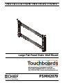
- Supports muraux à panneau plat
- Taper
- Guide d'installation


PSMH2079 Installation Instructions
2
DISCLAIMER
Milestone AV Technologies and its affiliated corporations and
subsidiaries (collectively “Milestone”), intend to make this
manual accurate and complete. However, Milestone makes no
claim that the information contained herein covers all details,
conditions or variations, nor does it provide for every possible
contingency in connection with the installation or use of this
product. The information contained in this document is subject
to change without notice or obligation of any kind. Milestone
makes no representation of warranty, expressed or implied,
regarding the information contained herein. Milestone assumes
no responsibility for accuracy, completeness or sufficiency of
the information contained in this document.
Chief® is a registered trademark of Milestone AV Technologies.
All rights reserved.
DEFINITIONS
MOUNTING SYSTEM: A MOUNTING SYSTEM is the
primary Chief product to which an accessory and/or component
is attached.
ACCESSORY: AN ACCESSORY is the secondary Chief
product which is attached to a primary Chief product, and may
have a component attached or setting on it.
COMPONENT: A COMPONENT is an audiovisual item
designed to be attached or resting on an accessory or mounting
system such as a video camera, CPU, screen, display,
projector, etc.
WARNING: A WARNING alerts you to the possibility of
serious injury or death if you do not follow the instructions.
CAUTION: A CAUTION alerts you to the possibility of
damage or destruction of equipment if you do not follow the
corresponding instructions.
IMPORTANT SAFETY INSTRUCTIONS
WARNING: Failure to read, thoroughly understand, and
follow all instructions can result in serious personal injury,
damage to equipment, or voiding of factory warranty! It is the
installer’s responsibility to make sure the mounting system is
properly assembled and installed using the instructions
provided.
WARNING: Failure to provide adequate structural strength
for this mounting system can result in serious personal injury
or damage to equipment! It is the installer’s responsibility to
make sure the structure to which this mounting system is
attached can support five times the combined weight of all
equipment. Reinforce the structure as required before
installing the mounting system.
WARNING: Exceeding the weight capacity can result in
serious personal injury or damage to equipment! It is the
installer’s responsibility to make sure the weight of the screen
does not exceed 350 lbs (158.8 kg).
WARNING: Use this mounting system only for its intended
use as described in these instructions. Do not use
attachments not recommended by the manufacturer.
WARNING: Never operate this mounting system if it is
damaged. Return the mounting system to a service center for
examination and repair.
WARNING: Do not use this product outdoors.
IMPORTANT ! :
The PSMH2079 mounts are designed to be
attached to:
•a bare 8" concrete or 8"x8"x16" concrete block wall, or
•a 2" x 4" wood studs wall covered by drywall with
maximum thickness of 5/8". Wood studs may be 16" or
24" on center.
--SAVE THESE INSTRUCTIONS--

Installation Instructions PSMH2079
3
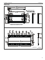
DIMENSIONS
23.62
600.0
SHOWN SET UP FOR A SCREEN WITH A MOUNTING
PATTERN OF 1200 mm WIDE X 600 mm TALL
LATCHING FLAGS CAN BE
2.51
63.8
26 X 3.00
76.2
0
0
.
0
1.00
25.4
DIMENSIONS: INCHES
[MILLIMETERS]

PSMH2079 Installation Instructions
4
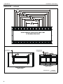
DIMENSIONS -- continued
47.24
1200.0
MOUNT UPRIGHTS CAN BE ATTACHED AT ANY
OF THE ABOVE SPACINGS
DISTANCE FROM TOP
OF SCREEN TO FIRST
MOUNTING HOLE 5.56
141.3 4.44
112.7
DISTANCE FROM TOP
OF SCREEN TO
FIRST MOUNTING HOLE
SHOWN WITH MICROSOFT
SURFACE HUB 84
SHOWN WITH MICROSOFT
SURFACE HUB 55
DIMENSIONS: INCHES
[MILLIMETERS]

Installation Instructions PSMH2079
5
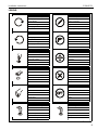
LEGEND
Tighten Fastener
Apretar elemento de fijación
Befestigungsteil festziehen
Apertar fixador
Serrare il fissaggio
Bevestiging vastdraaien
Serrez les fixations
Loosen Fastener
Aflojar elemento de fijación
Befestigungsteil lösen
Desapertar fixador
Allentare il fissaggio
Bevestiging losdraaien
Desserrez les fixations
Phillips Screwdriver
Destornillador Phillips
Kreuzschlitzschraubendreher
Chave de fendas Phillips
Cacciavite a stella
Kruiskopschroevendraaier
Tournevis à pointe cruciforme
Open-Ended Wrench
Llave de boca
Gabelschlüssel
Chave de bocas
Chiave a punte aperte
Steeksleutel
Clé à fourche
By Hand
A mano
Von Hand
Com a mão
A mano
Met de hand
À la main
Hex-Head Wrench
Llave de cabeza hexagonal
Sechskantschlüssel
Chave de cabeça sextavada
Chiave esagonale
Zeskantsleutel
Clé à tête hexagonale
Pencil Mark
Marcar con lápiz
Stiftmarkierung
Marcar com lápis
Segno a matita
Potloodmerkteken
Marquage au crayon
Drill Hole
Perforar
Bohrloch
Fazer furo
Praticare un foro
Gat boren
Percez un trou
Adjust
Ajustar
Einstellen
Ajustar
Regolare
Afstellen
Ajuster
Remove
Quitar
Entfernen
Remover
Rimuovere
Verwijderen
Retirez
Optional
Opcional
Optional
Opcional
Opzionale
Optie
En option
Security Wrench
Llave de seguridad
Sicherheitsschlüssel
Chave de segurança
Chiave di sicurezza
Veiligheidssleutel
Clé de sécurité

PSMH2079 Installation Instructions
6
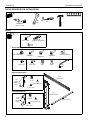
TOOLS REQUIRED FOR INSTALLATION
PARTS
7/32" - wood
#2
3/8" - concrete
1/2"
3/8"
A (6)
5/16 x 2-3/4" B (6)
[Fischer UX10x60R]
C (6)
5/16"
D (4)
[Mounting button] E (4)
M6x30mm F (4)
M8x25mm G (4) [Shoulder washer]
N (1)
3/16"
J (8)
5/16 x 1/2" K (16)
5/16 x 3/4" L (16)
5/16" M (16)
5/16"
P (1)
[Right
Q (1)
10-24"
R (1)
.375x.194x.032"
S (1)
10-24 x 1/2"‘
T (1)
[Left U (1)
10-24"
W (1)
.375x.194x.032"
V (1)
10-24 x 1/2"
Y (2)
[Upright bracket]
X (2)
[Wall plate]
Z (2)
[Side bracket]
Mounting Hardware Kit
Screen Attaching Hardware Kit
Right Latching Flag Kit
Left Latching Flag Kit
latching
flag]
latching
flag]
H (4)
M8x35mm

Installation Instructions PSMH2079
7
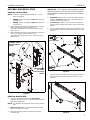
ASSEMBLY AND INSTALLATION
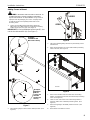
Attaching Latching Flags
NOTE: Determine if vertical mounting pattern on screen is
400mm or 600mm.
•400mm - Attach latching flag at lower mounting hole.
(See Figure 1)
•600mm - Attach latching flag at upper mounting hole.
(See Figure 1)
1. Attach right latching flag (P) to upright bracket (Y) using one
10-24 x 1/2" Phillips undercut screw (S), one
.375x.194x.032" spacer (R), and one 10-24 locknut (Q).
(See Figure 1)
2. Attach left latching flag (T) to upright bracket (Y) using one
10-24 x 1/2" Phillips undercut screw (V), one
.375x.194x.032" spacer (W), and one 10-24 locknut (U).
(See Figure 1)
Figure 1
Attaching Mount to Wall
1. Using the information included in the Dimensions
drawings, determine where to center and attach the top wall
plate of the PSMH2079.
NOTE: The wall plate mounting slots allow 3 inches of lateral
shift.
2. Wood stud only: Make sure that mounting slots in wall
plate (X) are placed over studs.
3. Mark three mounting locations through the wall plate
mounting slots.
IMPORTANT ! : The minimum spacing between outside
attachment points is 32 inches (81.3cm).The maximum
spacing between outside attachment points is 48 inches
(121.9cm).
4.
Wood stud:
Drill three 7/32" x 2-3/4" pilot holes at marked
locations.
Concrete:
Drill three 3/8" x 3-1/2" pilot holes at
marked locations. (See Figure 2)
5. Concrete only: Install an anchor (B) into each pilot hole
using a hammer, making sure that the anchor is flush with
the wall.
6. Secure upper wall plate (X) to wall using three 5/16 x 2-3/4"
hex head lag screws (A) and three 5/16" washers (C). (See
Figure 2)
Figure 2
7. Loosely install two side brackets (Z) to upper wall plate (X)
using four 5/16 x 1/2" button head cap screws (J).(See
Figure 3)
Figure 3
1
(P)
(T)
(W)
(U)
(Y)
(Q)
(R)
2
(S)
(V)
(Flag attachment
for 600mm vertical
mounting pattern
shown)
Attach flag here
for 400mm
vertical mounting
pattern
3
4
6
(A) x 3 (C) x 3
5
(B) x 3
(Concrete only)
(X)
7
(J) x 4
(Z)
(X)

PSMH2079 Installation Instructions
8
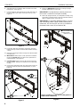
8. Slide wall plate (X) in between wall and lower end of side
brackets (Z). (See Figure 4)
9. Loosely install two side brackets (Z) to lower wall plate (X)
using four 5/16 x 1/2" button head cap screws (J). (See
Figure 4)
Figure 4
10. Level lower wall plate and tighten eight upper and lower
button head cap screws in side brackets installed in Steps
7 and 9.
11. Mark three mounting locations through the lower wall plate
mounting slots.
12.
Wood stud:
Drill three 7/32" x 2-3/4" pilot holes at marked
locations.
Concrete:
Drill three 3/8" x 3-1/2" pilot holes at
marked locations. (See Figure 5)
13.
Concrete only: Install an anchor (B) into each pilot hole
using a hammer, making sure that the anchor is flush with
the wall.
14. Secure lower wall plate to wall using three 5/16 x 2-3/4" hex
head lag screws (A) and three 5/16" washers (C). (See
Figure 5)
Figure 5
15. Reference Dimensions drawings for locating of upright
brackets dependent on screen size.
IMPORTANT ! : Upright brackets must be placed such
that screen is centered on wall plate assembly.
16. Attach two upright brackets (Y) to wall plate assembly using
eight 5/16 x 3/4" button head screws (K) and 5/16" washers
(M) per upright bracket. (See Figure 6)
IMPORTANT ! : If attaching upright brackets to a screen
with a mounting pattern OTHER THAN 1200mm wide x
600mm tall, also use the 5/16" lock nut (L) in addition to
the button head screws (K) and washers (M).
Figure 6
8
(Z)
(X)
9
(J) x 4
11
12
14
(A) x 3 (C)
13
(B) x 3
(Concrete only)
(Shows assembly for screen with mounting pattern of
1200mm wide x 600mm tall)
16
(K) x 16
(M) x 16
(Y) x 2
NOTE: Lock nuts (L)
also used if attaching
upright brackets
within this area.

Installation Instructions PSMH2079
9
Adding Screen to Mount
WARNING: IMPROPER INSTALLATION CAN LEAD TO
SCREEN FALLING CAUSING SERIOUS PERSONAL
INJURY OR DAMAGE TO EQUIPMENT! Using screws of
improper size may damage your screen. Properly sized
screws will easily and completely thread into screen
mounting holes.
1. Select correct button head screws [M6 x 30mm (E),
M8 x 25mm (F) or M8 x 35mm (G)] and attach mounting
buttons (D) to back of screen. (See Figure 7)
IMPORTANT ! : If using M6 button head screws (E), also
use the shoulder washers (H). (See Figure 7)
Figure 7
2. Move latching flags on mount to the OPEN position. (See
Figure 8)
Figure 8
3. Lift screen following lifting instructions provided by screen
manufacturer.
4. Align mounting buttons on screen with teardrop mounting
holes in mount. (See Figure 9)
Figure 9
5. Move screen forward until recessed area of mounting
buttons is positioned over lower area of teardrop mounting
holes. (See Figure 9)
6. Lower screen until recess area of mounting buttons is
seated in lower area of teardrop mounting holes. (See
Figure 9)
7. Move locking flags to CLOSED position and lock. (See
Figure 8)
8. Route wires and cables to screen.
1
(F) x 4
(D) x 4
1
(E) x 4
(D)
(H)
Installation
with M6
screws and
[Example:
Installation with
M8 screws shown]
shoulder
washers (H)
shown]
[Example:
CLOSED
OPEN
5
6
Screen

PSMH2079 Installation Instructions
10

Installation Instructions PSMH2079
11

PSMH2079 Installation Instructions
USA/International A 6436 City West Parkway, Eden Prairie, MN 55344
P800.582.6480 / 952.225.6000
F877.894.6918 / 952.894.6918
Europe A Franklinstraat 14, 6003 DK Weert, Netherlands
P+31 (0) 495 580 852
F+31 (0) 495 580 845
Asia Pacific A Office No. 918 on 9/F, Shatin Galleria
18-24 Shan Mei Street
Fotan, Shatin, Hong Kong
P852 2145 4099
F852 2145 4477
Chief, a products division of
Milestone AV Technologies
8800-002809 Rev01
2016 Milestone AV Technologies
www.milestone.com
03/16
-
 1
1
-
 2
2
-
 3
3
-
 4
4
-
 5
5
-
 6
6
-
 7
7
-
 8
8
-
 9
9
-
 10
10
-
 11
11
-
 12
12


Chief PSMH2079 Guide d'installation
- Catégorie
- Supports muraux à panneau plat
- Taper
- Guide d'installation
dans d''autres langues
- English: Chief PSMH2079 Installation guide
Documents connexes
-
Chief JWSVB Guide d'installation
-
Chief JWDIWUB Guide d'installation
-
-
-
-
-
-
Chief PACCS1 Guide d'installation
-
-