Bosch GTR55-85 9 Manuel utilisateur
- Catégorie
- Outils électroportatifs
- Taper
- Manuel utilisateur

Operating / Safety Instructions
Consignes d’utilisation / de sécurité
Instrucciones de funcionamiento y seguridad
Call Toll Free for Consumer Information & Service Locations
Pour obtenir des informations et les adresses de nos centres de service après-vente, appelez ce numéro gratuit
Llame gratis para obtener información para el consumidor y ubicaciones de servicio
For English Version
See page 2 ●Version française
Voir page 23 ●Versión en español
Ver la página 44
IMPORTANT
Read Before Using ●IMPORTANT
Lire avant usage ●IMPORTANTE
Leer antes de usar
1-877-BOSCH99 (1-877-267-2499) www.boschtools.com
GTR55-85

-2-
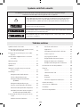
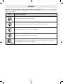
The definitions below describe the level of severity for each signal word.
Please read the manual and pay attention to these symbols.
!This is the safety alert symbol. It is used to alert you to potential personal injury hazards.
Obey all safety messages that follow this symbol to avoid possible injury or death.
DANGER indicates a hazardous situation which, if not avoided, will result in death or serious
injury.
WARNING indicates a hazardous situation which, if not avoided, could result in death or
serious injury.
CAUTION indicates a hazardous situation which, if not avoided, could result in minor or
moderate injury.
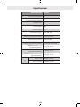
Table of Contents
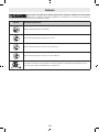
Safety Symbols
Safety Symbols .................................2
General Power Tool Safety Warnings ................3
Safety Rules for Random Orbital
Sanders ...................................5
Additional Safety Warnings .......................6
Intended Use...................................6
Specifications ..................................7
Symbols.......................................8
Getting to Know Your Drywall Sander ............. 10
Assembly.................................... 12
Changing the Sanding Sheet................. 12
Selection of the Sanding Pad ................ 12
Changing the Intermediate Pad (GTR800) ..... 12
Changing the Sanding Pad .................. 13
Inserting and Removing
Extension Tubes....................... 13
Attaching the Vacuum Hose ................. 14
Installing/Removing the
Hose/Cable Clip . . . . . . . . . . . . . . . . . . . . . . . 14
Dry Wall Sander Operation...................... 15
Starting Operation......................... 15
Preselecting the Speed..................... 15
Applications.............................. 15
On/Off Slide Switch........................ 15
Sanding Surfaces ......................... 16
Sanding Close to Edges..................... 16
Adjusting the Internal/External
Airflow............................... 16
Adjusting Suction Power.................... 17
Changing the Connection Hose .............. 17
Troubleshooting .............................. 19
Maintenance ................................. 21
Service .................................. 21
Tool Lubrication........................... 21
Motors .................................. 21
Cleaning ................................. 21
Accessory Storage and
Maintenance.......................... 21
Extension Cords .............................. 22
Accessories and Attachments ................... 22

-3-
General Power Tool Safety Warnings
Read all safety warnings, instructions, illustrations and specifications provided with this power
tool. Failure to follow all instructions listed below may result in electric shock, fire and/or serious injury.
SAVE ALL WARNINGS AND INSTRUCTIONS FOR FUTURE REFERENCE
The term “power tool” in the warnings refers to your mains-operated (corded) power tool or battery-operated (cordless) power
tool.
SAVE THESE INSTRUCTIONS
1. Work Area Safety
a. Keep work area clean and well lit. Cluttered or dark
areas invite accidents.
b. Do not operate power tools in explosive atmospheres,
such as in the presence of flammable liquids, gases
or dust. Power tools create sparks which may ignite the
dust or fumes.
c. Keep children and bystanders away while operating a
power tool. Distractions can cause you to lose control.
2. Electrical Safety
a. Power tool plugs must match the outlet. Never modify
the plug in any way. Do not use any adapter plugs
with earthed (grounded) power tools. Unmodified
plugs and matching outlets will reduce risk of electric
shock.
b. Avoid body contact with earthed or grounded surfac-
es, such as pipes, radiators, ranges and refrigerators.
There is an increased risk of electric shock if your body is
earthed or grounded.
c. Do not expose power tools to rain or wet conditions.
Water entering a power tool will increase the risk of
electric shock.
d. Do not abuse the cord. Never use the cord for carrying,
pulling or unplugging the power tool. Keep cord away
from heat, oil, sharp edges or moving parts. Damaged or
entangled cords increase the risk of electric shock.
e. When operating a power tool outdoors, use an exten-
sion cord suitable for outdoor use. Use of a cord suit-
able for outdoor use reduces the risk of electric shock.
f. If operating a power tool in a damp location is
unavoidable, use a Ground Fault Circuit Interrupter
(GFCI) protected supply. Use of an GFCI reduces the
risk of electric shock.
3. Personal Safety
a. Stay alert, watch what you are doing and use common
sense when operating a power tool. Do not use a
power tool while you are tired or under the influence of
drugs, alcohol or medication. A moment of inatten-
tion while operating power tools may result in serious
personal injury.
b. Use personal protective equipment. Always wear eye
protection. Protective equipment such as a dust mask,
non-skid safety shoes, hard hat, or hearing protection
used for appropriate conditions will reduce personal
injuries.
c. Prevent unintentional starting. Ensure the switch is in
the off-position before connecting to power source and /
or battery pack, picking up or carrying the tool. Carrying
power tools with your finger on the switch or energizing
power tools that have the switch on invites accidents.
d. Remove any adjusting key or wrench before turning
the power tool on. A wrench or a key left attached to
a rotating part of the power tool may result in personal
injury.
e. Do not overreach. Keep proper footing and balance at
all times. This enables better control of the power tool in
unexpected situations.
f. Dress properly. Do not wear loose clothing or jewelry.
Keep your hair and clothing away from moving parts.
Loose clothes, jewelry or long hair can be caught in
moving parts.
h. Do not let familiarity gained from frequent use of
tools allow you to become complacent and ignore tool
safety principles. A careless action can cause severe
injury within a fraction of a second.
4. Power Tool Use and Care
a. Do not force the power tool. Use the correct power
tool for your application. The correct power tool will
do the job better and safer at the rate for which it was
designed.
b. Do not use the power tool if the switch does not turn
it on and off. Any power tool that cannot be controlled
with the switch is dangerous and must be repaired.
c. Disconnect the plug from the power source and/or
remove the battery pack from the power tool before
making any adjustments, changing accessories, or

-4-
General Power Tool Safety Warnings
storing power tools. Such preventive safety measures
reduce the risk of starting the power tool accidentally.
d. Store idle power tools out of the reach of children and
do not allow persons unfamiliar with the power tool
or these instructions to operate the power tool. Power
tools are dangerous in the hands of untrained users.
e. Maintain power tools and accessories. Check for
misalignment or binding of moving parts, breakage
of parts and any other condition that may affect the
power tool’s operation. If damaged, have the power
tool repaired before use. Many accidents are caused by
poorly maintained power tools.
f. Keep cutting tools sharp and clean. Properly main-
tained cutting tools with sharp cutting edges are less
likely to bind and are easier to control.
g. Use the power tool, accessories and tool bits etc.
in accordance with these instructions, taking into
account the working conditions and the work to be
performed. Use of the power tool for operations dif-
ferent from those intended could result in a hazardous
situation.
h. Keep handles and grasping surfaces dry, clean and
free from oil and grease. Slippery handles and grasping
surfaces do not allow for safe handling and control of the
tool in unexpected situations.
5. Service
a. Have your power tool serviced by a qualified repair
person using only identical replacement parts.
This will ensure that the safety of the power tool is
maintained.
SAVE THESE INSTRUCTIONS

-5-
Safety Rules for Random Orbital Sanders
a. Hold power tool by insulated gripping surfaces, when
performing an operation where the sanding disk may
contact its own cord. Sanding disk contacting a “live”
wire may make exposed metal parts of the power tool
“live” and could give the operator an electric shock.
b. Unplug the sander before changing accessories. Ac-
cidental start-ups may occur if sander is plugged in while
changing an accessory.
c. If your tool is equipped with a dust bag, empty it fre-
quently and after completion of sanding. Be extremely
careful of dust disposal, materials in fine particle form
may be explosive. Do not throw sanding dust on an open
fire. Spontaneous combustion may, in time, result from
mixture of oil or water with dust particles.
d. Always wear eye protection and a dust mask for dusty
applications and when sanding overhead. Sanding
particles can be absorbed by your eyes and inhaled eas-
ily and may cause health complications.
e. Use special precautions when sanding chemically
pressure treated lumber, paint that may be lead
based, or any other materials that may contain car-
cinogens. A suitable breathing respirator and protective
clothing must be worn by all persons entering the work
area. Work area should be sealed by plastic sheeting and
persons not protected should be kept out until work area
is thoroughly cleaned.
f. Do not wet sand with this sander. Liquids entering the
motor housing is an electrical shock hazard.
g. Do not use PSA pad on random orbit sanders whose
speed exceeds 12,000/min. Exceeding the maximum
operating speed of pad may cause pad to rupture or fly
apart during use striking user or bystanders.
h. Do not use sandpaper intended for larger sanding
pads. Larger sandpaper will extend beyond the sanding
pad causing snagging, tearing of the paper or kick-back.
Extra paper extending beyond the sanding pad can also
cause serious lacerations.
i. Be aware of the location and setting of the Switch
“Lock-ON” Button. If the switch is locked “ON”, be ready
for emergency situations to switch it “OFF”, by first
pulling the trigger then immediately releasing it without
pressing the “Lock-ON” button.
j. Clamp or secure workpiece when sanding. Clamping
the workpiece prevents it from being ejected from under
the sander and leaves both hands to control the tool.
k. Keep the cord away from the spinning pad and sand-
paper. The cord can become entangled with the pad.
SAVE THESE INSTRUCTIONS

-6-
SAVE THESE INSTRUCTIONS
Do not hold the vacuum hose against any body parts dur-
ing operation. Static electricity build-up in the hose during
operation may result in static shock.
GFCI and personal protection devices like electrician’s rubber
gloves and footwear will further enhance your personal safety.
Do not use AC only rated tools with a DC power supply.
While the tool may appear to work, the electrical components
of the AC rated tool are likely to fail and create a hazard to the
operator.
Develop a periodic maintenance schedule for your tool.
When cleaning a tool be careful not to disassemble any
portion of the tool since internal wires may be misplaced
or pinched or safety guard return springs may be improp-
erly mounted. Certain cleaning agents such as gasoline, car-
bon tetrachloride, ammonia, etc. may damage plastic parts.
Use this tool only as intended. Un-
intended use may result in personal
injury and property damage.
The power tool is intended for dry sanding dry wall that has
had drywall plaster applied to close seams and blemishes,
ceilings and walls in indoor and outdoor areas, and for remov-
ing coats of paint, adhesive residues and loose plaster.
This power tool is not suitable for bench-mounted use. It
must not be clamped into a vice or fastened to a workbench.
Some dust created by power sand-
ing, sawing, grinding, drilling, and
other construction activities contains chemicals known to
cause cancer, birth defects or other reproductive harm.
Some examples of these chemicals are:
• Lead from lead-based paints,
• Crystalline silica from bricks and cement and other
masonry products, and
• Arsenic and chromium from chemically-treated lumber.
Your risk from these exposures varies, depending on how
often you do this type of work. To reduce your exposure to
these chemicals: work in a well ventilated area, and work with
approved safety equipment, such as those dust masks that
are specially designed to filter out microscopic particles.
Additional Safety Warnings
Intended Use

-7-
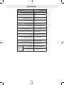
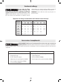
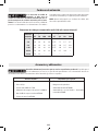
Specifications
Model Number GTR55-85
Speed preselection
Constant electronic control
Soft start
Voltage rating 120 V
Rated power 4.5A
No-load speed n₀ min−1 340–910
Sanding pad diameter 8.5" (215 mm)
Sanding sheet diameter 9" (225 mm)
Dust extraction diameter 1.7/1.3" (45/35 mm)
Short version length
(without extension tube) 43.31" (1.1 m)
Standard version length
(with one extension tube) 66.93" (1.7 m)
Long version length
(with two extension tubes) 90.55" (2.3 m)
Weight
Short version 9.04 lbs (4.1 kg)
Standard version 10.58 lbs (4.8 kg)

-8-
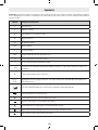
Symbols
Important: Some of the following symbols may be used on your tool. Please study them and learn their meaning. Proper inter-
pretation of these symbols will allow you to operate the tool better and safer.
Symbol Designation/Explanation
V Volts (voltage)
A Amperes (current)
Hz Hertz (frequency, cycles per second)
W Watt (power)
kg Kilograms (weight)
min Minutes (time)
s Seconds (time)
⌀Diameter (size of drill bits, grinding wheels, etc.)
n0No load speed (rotational speed, at no load)
n Rated speed (Maximum attainable speed)
.../min Revolutions or reciprocation per minute (revolutions, strokes, surface speed, orbits etc. per minute)
0 Off position (zero speed, zero torque...)
1, 2, 3, ...
I, II, III, Selector settings (speed, torque or position settings. Higher number means greater speed)
0
Infinitely variable selector with off (speed is increasing from 0 setting)
Arrow (action in the direction of arrow)
Alternating current (type or a characteristic of current)
Direct current (type or a characteristic of current)
Alternating or Direct current (type or a characteristic of current)
Class II construction (designates Double Insulated Construction tools)
Earthing terminal (grounding terminal)

-9-
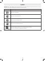
Symbols
Important: Some of the following symbols may be used on your tool. Please study them and learn their meaning. Proper inter-
pretation of these symbols will allow you to operate the tool better and safer.
Symbol Designation/Explanation
Alerts user to read manual.
Alerts user to wear eye protection.
Alerts user to wear hearing protection.
Alerts user to wear respiratory protection.
This symbol designates that this tool is listed by the Canadian Standards
Association, to United States and Canadian Standards.

-10-
Disconnect power cord from tool before making any assembly, adjustments or changing acces-
sories. Such preventive safety measures reduce the risk of starting the tool accidentally.
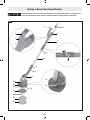
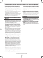
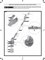
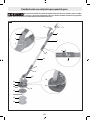
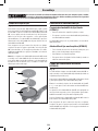
Getting to Know Your Drywall Sander
1
2
4
8
6
10
3
14
15
17
19
5
9
7
13
12
8
9
11
13
16
18
20
9
Fig. 1

-11-
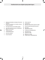
Getting to Know Your Drywall Sander
1 Suction Power Thumbwheel
2 Speed Preselection Thumbwheel
3 On/Off Slide Switch
4 Handle (Insulated Gripping Surface)
5 Vacuum Hose
6 Vacuum Outlet
7 Handle Section
8 Safety Hook
9 Clamping Lever
10 Extension Tube
11 Sanding Head
12 Brush Segment Locking Mechanism
13 Suction Power Adjusting Lever
14 Sanding Sheet
15 Intermediate Pad
16 Screw for Sanding Pad
17 Sanding Pad
18 Brush Segment
19 Connection Hose
20 Sanding Pad Holder

-12-
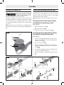
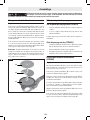
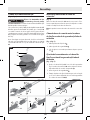
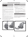
Changing the Sanding Sheet
(Fig. 2)
To remove the Sanding Sheet 14, lift it from the side and
pull it off the Intermediate Pad 15. Remove any dirt or debris
from Intermediate Pad 15 with a brush before attaching a
new sanding sheet. Use hook and loop style sanding sheets
to properly secure to Intermediate Pad 15, press the Sanding
Sheet 14 firmly onto the underside of the Intermediate Pad
15.
To ensure optimum dust extraction, make sure that the
punched holes in the Sanding Sheet 14 are aligned with the
punched holes in the Intermediate Pad 15 and the drilled
holes in the Sanding Pad 17.
Note: An Intermediate Pad 15 is not required when working
with the medium-hard sanding pad; the Sanding Sheet 14 is
attached directly to the Sanding Pad 17. In all other cases, the
change is performed as described here.
Assembly
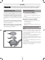
Selection of the Sanding Pad
Soft Sanding Pad Set (GTR801)
• For universal use on flat and curved surfaces.
• The set consists of a soft sanding pad and an intermedi-
ate pad.
The sanding pad may only be used with an intermediate pad.
Medium/Hard Sanding Pad (GTR802)
• High material removal rate, ideal for hard plaster and
removing old wall paints
• For use on flat surfaces
• Optimal suction support makes work easier when using
a dust extractor.
Changing the Intermediate Pad (GTR800)
(Fig. 2)
An Intermediate Pad 15 must always be used when working
with the soft sanding pad (included with the drywall sander).
To remove the Intermediate Pad 15 lift it from the side and pull
it off the Sanding Pad 17.
Remove dirt and dust from the Sanding Pad 17, e.g. with a
paintbrush, before attaching a new intermediate pad.
The surface of the Sanding Pad 17 is fitted with a hook-and-
loop fastening, allowing intermediate pads to be secured
quickly and easily.
Press the Intermediate Pad 15 firmly against the underside of
the Sanding Pad 17.
To ensure optimum dust extraction, make sure that the
punched holes in the Intermediate Pad 15 are aligned with
the drilled holes in the Sanding Pad 17.
Disconnect power cord from tool before making any assembly, adjustments or changing acces-
sories. Such preventative safety measures reduce the risk of starting the tool accidentally.
Fig. 2
14
15
17

-13-
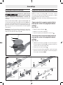
Changing the Sanding Pad
(Fig. 2, Fig. 3)
Observe for and replace damaged
sanding pad immediately. Using a
damaged sanding pad could cause a hazard.
Pull off the Sanding Sheet 14 and the Intermediate Pad
15. While grabbing the Sanding Pad 17, turn the screw 16
counter-clockwise to loosen completely and remove it. Attach
the new Sanding Pad 17 and retighten the screw by turning
it clockwise.
Note: For proper fit, the keyed hub on the sanding pad must
align with the keyed flange on the Sanding Head Output Shaft
21.
Assembly
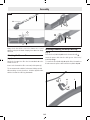
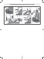
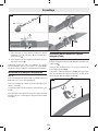
Inserting and Removing Extension Tubes
(Fig. 4)
Use the Extension Tubes 10 when necessary. The effort re-
quired to perform the sanding operation is reduced when
working without the extension tube.
Note: A maximum of two extension tubes may be inserted.
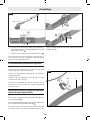
Undoing the Connection between Sanding
Head/Handle Section/Extension Tube
(Fig. 1, Fig. 4)
1. Open the Clamping Lever 9 .
2. Open the Safety Hook 8 .
3. Pull the previously connected parts apart .
Fastening the Connection between Sanding
Head/Handle Section/Extension Tube
(Fig. 1, Fig. 5)
1. Slide the Sanding Head 11, Handle Section 7, and/or
Extension Tubes 10 into each other depending on the
required connection .
2. Close the Safety Hook 8 .
3. Push the Clamping Lever 9 until it is at a right angle to
the Sanding Head 11, Handle Section 7, or Extension
Tube 10 .
4. To avoid loosening during operation, firmly tighten the
Eccentric Screw 22 clockwise .
5. Close the Clamping Lever 9 by pressing it back in place
.
17
16
21
Fig. 3
9
8
8
9
10
7
11
10
11
10 7
10
7
11
Fig. 4

-14-
Always check that all the connection elements are secured
with the Safety Hooks 8 and clamping levers 9 and are firmly
attached.
Attaching the Vacuum Hose
(Fig. 1)
Attach the Vacuum Hose 5 to the Vacuum Outlet 6 on the
Handle Section 7.
Connect the Vacuum Hose 5 to a vacuum (sold separately).
The vacuum must be suitable for the material being sanded.
When working on vertical surfaces, hold the drywall sander
with the Vacuum Hose 5 facing downwards.
Installing/Removing the Hose/Cable Clip
(Fig. 6)
Place the Hose/Cable Clip 23 over the Vacuum Hose 5 .
Insert the power cable into the cable groove of the Hose/
Cable Clip 23 .
To remove the Hose/Cable Clip 23, pull it off the Vacuum Hose
5 and remove the power cable from the Hose/Cable Clip 23.
Assembly
5
23
Fig. 6
7
11
922
8
89
Fig. 5

-15-
Dry Wall Sander Operation
Starting Operation
Pay attention to the mains voltage. The voltage of the power
source must match the voltage specified on the rating plate of
the power tool. Power tools marked with 120V can and should
be operated with 120V.
Preselecting the Speed
You can preselect the required speed using the Speed Pre-
selection Thumbwheel 2, even during operation. The higher
numbers indicate a high speed, while the smaller ones repre-
sent a low speed.
The Constant Electronic keeps the speed at no load and under
load virtually consistent, producing uniform performance.
The electronic soft start limits the torque when the power tool
is switched on and increases the service life of the motor.
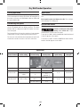
Applications
See the table "Applications" below for application informa-
tion.
Do not put the power tool down on its side. This could per-
manently warp the sanding pad.
On/Off Slide Switch
(Fig. 1)
Hold the tool with both hands while
turning on or off the tool. Torque
from the motor can cause the tool to twist.
To turn the tool "ON," slide the On/Off Slide Switch 3 forward
so that "I" appears on the switch.
To turn the tool "OFF," slide the On/Off Slide Switch 3 back-
wards so that "0" appears on the switch.
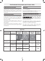
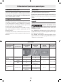
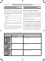
Applications
joint compound/
plaster hardness wall or ceiling
internal/external
air flow setting suction power speed setting
sanding
sheet grit
very soft/soft wall or ceiling 1 6 2–4 from P180
medium hardness
wall 1 6
4–6 from P120
ceiling 3 1–5
(optimum: 3)
extremely hard wall or ceiling
1 on uneven
surfaces 64–6 from P100
3 on even surfaces 1–3

-16-
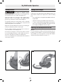
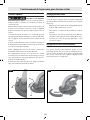
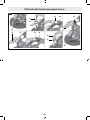
Sanding Close to Edges
(Fig. 7, Fig. 8)
Taking out the removable Brush Segment 18 helps reduce the
lateral distance between the edges/corners and the sanding
pad.
• Press and hold the Locking Mechanism 12 for the Brush
Segment 18.
• Swivel the Brush Segment 18 forwards and remove it.
• To insert, hook the Brush Segment 18 onto the opposite
side of the Locking Mechanism 12, and swivel it towards
the Sanding Head 11 until it clicks into place.
Adjusting the Internal/External Airflow
(Fig. 1)
You can switch between different air flow operating modes de-
pending on the intended use. Turn the Suction Power Adjust-
ing Lever 13 to one of the 3 positions. (See the table "Adjust-
ing the Internal/External Airflow" on page 17.)
Dry Wall Sander Operation
Sanding Surfaces
Always wait until the power tool
has come to a complete stop be-
fore placing it down. The spinning accessory may grab a sur-
face and cause you to lose control of the power tool.
Switch the power tool on, place the entire sanding surface
against the surface of the workpiece and apply moderate
pressure as you move the sander over the workpiece.
The material removal rate and sanding result are primarily
determined by the choice of sanding sheet, the preselected
speed setting and the contact pressure.
Only new or unused sanding sheets achieve good sanding per-
formance and make the power tool last longer.
Be sure to apply consistent contact pressure in order to in-
crease the lifetime of the sanding sheets.
Excessively increasing the contact pressure will not lead to
increased sanding performance, rather it will cause more se-
vere wear of the power tool and of the sanding sheet.
Do not use a sanding sheet for other materials after it has been
used to work on metal.
Fig. 8
12
18
11
Fig. 7

-17-
Dry Wall Sander Operation
Adjusting Suction Power
(Fig. 1)
You can adjust the suction power to achieve your preferred
balance between sanding speed and suction power. This is
only possible when the Suction Power Adjusting Lever 13 is
set to position 3. (See the table "Adjusting the Internal/Exter-
nal Airflow" below.)
Adjust the suction power with the Thumbwheel 1:
• 1−5: Low to high suction power, suitable for sanding
ceilings
• 6: Highest suction power, suitable for sanding walls
Start with a low suction power (position 1) and increase slow-
ly, until there is a noticeable contact pressure.
High suction power allows low-fatigue sanding of ceilings and
walls. An excessively high suction power can cause the power
tool to vibrate, which can make handling more difficult.
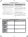
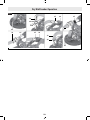
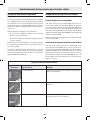
Changing the Connection Hose
(Fig. 9)
Removing the Connection Hose
To remove the Connection Hose 19, loosen the screw on the
Hose Clamp 24 with a screwdriver and lift the Hose Clamp 24
off with the Connection Hose 19. Remove the Hose Clamp
24. Pull out the Inner Housing 25 of the Hose Mount 26 at the
other end of the Connection Hose 19.
Hold the Inner Housing 25 in place and unscrew the Connec-
tion Hose 19.
Inserting a New Connection Hose
To insert a new Connection Hose 19, hold the Inner Hous-
ing 25 in place and screw in the new Connection Hose 19 all
the way. Fit the hose Hose Clamp 24 on the other side of the
Connection Hose 19. Position the screw head so that you can
tighten the Hose Clamp 24 effortlessly on the Sanding Head
11 with a screwdriver with a torque of around 17.7 Lbf-in
(2 Nm).
Adjusting the Internal/External Airflow
switch position type of airflow use
1 - External airflow Ideal for sanding walls at high sanding speeds without
vacuum suction.
2 - Mixed external and internal airflow Medium sanding performance with low vacuum suction.
3 - Mixed external and internal airflow Ideal for sanding ceilings at low sanding speeds but with
high vacuum suction.

-18-
Dry Wall Sander Operation
19
19
19
19
24
24
24
24
25
25 25
25
26
26
Fig. 9

-19-
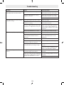
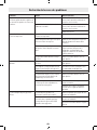
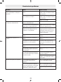
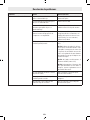
Troubleshooting
Problem Cause Corrective Action
The drywall sander does not run
smoothly or jolts across the surface.
The suction effect is too strong. Reduce the suction power or switch to
external dust extraction, if necessary.
The joint compound material and/or
substrates are hard.
Reduce the suction power or switch to
external dust extraction, if necessary.
Reduce the speed.
The removal rate of the material being
sanded is too high.
The drywall sander's speed is too high. Reduce the speed.
The suction effect on the drywall
sander is too strong.
Reduce the suction effect or switch to
external dust extraction.
The joint compound material has a high
proportion of compound or is very soft.
Switch on the external dust extraction,
set the suction power thumbwheel to
setting 6 and, in extreme cases, reduce
the speed.
The grit of the abrasive is too coarse. Use a sanding sheet with a finer grit.
The surface quality is not optimal. The grit of the abrasive is too coarse. Use a sanding sheet with a finer grit.
The drying times for the joint
compound material have not been
observed.
Refer to the technical information
sheets and manufacturer's recom-
mendations.
The suction effect is too strong. Reduce the suction power.
The joint compound material has a high
proportion of filler or is very soft.
Use a sanding sheet with a finer grit.
The drywall sander's head scratches
the drywall while operating (scoring).
Position the power tool before switch-
ing it on.
Work on the surface and always work
with the removable brush segment.
There are sanding marks on the
surface.
The hard sanding pad has been posi-
tioned at an angle on the surface.
Use a soft sanding pad with an interme-
diate pad.
In the case of very soft joint compound
material, the sanding pad is too hard or
the grit of the abrasive is too coarse.
Use a soft sanding pad with an interme-
diate pad.
Choose a finer abrasive grit.

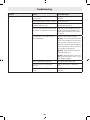
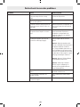
-20-
Problem Cause Corrective Action
The suction effect is insufficient. The suction power on the dust extrac-
tor is too low.
Increase the suction power on the dust
extractor.
The drywall sander's speed is too high. Reduce the speed.
The internal dust extraction on the
drywall sander is too low.
Reduce the suction power or switch to
external dust extraction.
The joint compound material has a high
proportion of compound or is very soft.
Switch on the external dust extraction,
set the suction power thumbwheel to
setting 6 and, in extreme cases, reduce
the speed.
The main filter on the dust extractor is
blocked/jammed.
Clean the filter element regularly:
Option 1: Set the suction power regu-
lation to the maximum suction power.
Seal the nozzle, extraction hose or in-
take port on the dust extractor with the
palm of your hand for 10 seconds until
the automatic cleaning starts.
Option 2: Clean the filter element me-
chanically (extraction).
Option 3: Check the filter element for
damage and blockages. Insert a new
filter element regularly.
A fleece dust bag is being used. Use a waste disposal dust bag.
The extraction hose is blocked or
twisted.
Remove the blockage or untwist the
hose.
The dust extractor's dust container
is full.
Empty the dust extractor's dust
container.
Troubleshooting
La page charge ...
La page charge ...
La page charge ...
La page charge ...
La page charge ...
La page charge ...
La page charge ...
La page charge ...
La page charge ...
La page charge ...
La page charge ...
La page charge ...
La page charge ...
La page charge ...
La page charge ...
La page charge ...
La page charge ...
La page charge ...
La page charge ...
La page charge ...
La page charge ...
La page charge ...
La page charge ...
La page charge ...
La page charge ...
La page charge ...
La page charge ...
La page charge ...
La page charge ...
La page charge ...
La page charge ...
La page charge ...
La page charge ...
La page charge ...
La page charge ...
La page charge ...
La page charge ...
La page charge ...
La page charge ...
La page charge ...
La page charge ...
La page charge ...
La page charge ...
La page charge ...
La page charge ...
La page charge ...
La page charge ...
La page charge ...
-
 1
1
-
 2
2
-
 3
3
-
 4
4
-
 5
5
-
 6
6
-
 7
7
-
 8
8
-
 9
9
-
 10
10
-
 11
11
-
 12
12
-
 13
13
-
 14
14
-
 15
15
-
 16
16
-
 17
17
-
 18
18
-
 19
19
-
 20
20
-
 21
21
-
 22
22
-
 23
23
-
 24
24
-
 25
25
-
 26
26
-
 27
27
-
 28
28
-
 29
29
-
 30
30
-
 31
31
-
 32
32
-
 33
33
-
 34
34
-
 35
35
-
 36
36
-
 37
37
-
 38
38
-
 39
39
-
 40
40
-
 41
41
-
 42
42
-
 43
43
-
 44
44
-
 45
45
-
 46
46
-
 47
47
-
 48
48
-
 49
49
-
 50
50
-
 51
51
-
 52
52
-
 53
53
-
 54
54
-
 55
55
-
 56
56
-
 57
57
-
 58
58
-
 59
59
-
 60
60
-
 61
61
-
 62
62
-
 63
63
-
 64
64
-
 65
65
-
 66
66
-
 67
67
-
 68
68


Bosch GTR55-85 9 Manuel utilisateur
- Catégorie
- Outils électroportatifs
- Taper
- Manuel utilisateur
dans d''autres langues
- English: Bosch GTR55-85 9 User manual
- español: Bosch GTR55-85 9 Manual de usuario