CAME 3199ZL90, 3199ZL90110 Spare Parts Manual
- Taper
- Spare Parts Manual

RICAMBI ORIGINALI
ORIGINAL SPARE PARTS
PIECES DE RECHANGE ORIGINALES
ORIGINALERSATZTEILE
REPUESTOS ORIGINALES
ORIGINEEL ONDERDEEL
SCHEDA ELETTRONICA
CONTROL BOARD
CARTE ELECTRONIQUE
STEUER PLATINE
TARJETA ELECTRONICA
ELEKTRONISCHE PRINTKAART
Nederlands NL
Español ES
Deutch DE
Français FR
English EN
Italiano IT
ZL90

L1T L2T
LNM1 N1
ENC1
M2 N2
ENC2
10 11 E1 1233P 457CX CY TS
B1 B2
2345678910
26V 17V 0V
T.PROTECTION
BA
G
C
F
E
D
L1T L2T
LNM1 N1
ENC1
M2 N2
ENC2
10 11 E1 1233P 457CX CY TS
B1 B2
2345678910
26V 17V 0V
T.PROTECTION
BA
G
C
F
E
D

ITALIANO
Pag.
3
- Codice manuale:
319
319
LR0
LR0
7
ver.
1.0
1.0 11/2007 © CAME cancelli automatici s.p.a.
I dati e le informazioni indicate in questo manuale sono da ritenersi suscettibili di modifica in qualsiasi momento e senza obbligo di preavviso da parte di CAME cancelli automatici s.p.a.
Collegamento antenna
Alimentazione 230V (a.c.) 50/60 Hz
Collegamenti elettrici
Pulsante di stop (contatto N.C.)
2-CX
2-4
2-3P
2-3
1-2
10-11
B1-B2
Uscita eventuale secondo canale del ricevitore radio (N.O.).
Portata contatto: 5A-24V (d.c.).
L-N
Alimentazione accessori 24V (a.c.)
M1-N1-ENC1 Motoriduttore 24V d.c. ad azione ritardata in apertura
M2-N2-ENC2 Motoriduttore 24V d.c. ad azione ritardata in chiusura
10-E1
Lampeggiatore di segnalazione (portata
contatto: 24V - 25W max.)
Spia cancello aperto (Portata contatto: 24V - 3W max.).
10-5
2-CY -Contatto (N.C.) di «stop parziale»/«attesa ostacolo»
(vedi Selezioni Funzioni, pag. 5)
Contatto (N.C.) di «riapertura durante la chiusura»
Selettore a chiave e/o pulsante di apertura (N.O.)
Selettore a chiave e/o pulsante di apertura parziale (N.O.)
Selettore a chiave e/o pulsante di chiusura (N.O.)
2-7
Selettore a chiave e/o pulsante per comandi (N.O.)
IT
-Collegare il cavo RG58 dell’antenna agli appositi morsetti.
-Innestare la scheda di radiofrequenza sulla scheda elettronica D DOPO AVER TOLTO LA TENSIONE (o scollegato le batterie).
N.B.: La scheda elettronica riconosce la scheda di radiofrequenza solo quando viene alimentata.
Attivazione del comando radio
Memorizzazione
B C
CH1 = Canale per comandi diretti a una funzione della scheda del moto-
riduttore (comando “solo apre” / “apre-chiude-inversione” oppure
“apre-stop-chiude-stop”, a seconda della selezione effettuata sui
dip-switch 2 e 3).
CH2 = Canale per comando diretto a un dispositivo accessorio collegato
su B1-B2.
-Tenere premuto il tasto “CH1” sulla scheda elettronica. Il led lampeggia.
-Premere il tasto del trasmettitore da memorizzare. Il led rimarrà acceso a segnalare l’avvenuta memorizzazione.
-Ripetere la procedura del punto 1 e 2 per il tasto “CH2” associandolo con un altro tasto del trasmettitore.

ITALIANO
I dati e le informazioni indicate in questo manuale sono da ritenersi suscettibili di modifica in qualsiasi momento e senza obbligo di preavviso da parte di CAME cancelli automatici s.p.a.
Pag.
4
- Codice manuale:
319
319
LR0
LR0
7
ver.
1.0
1.0 11/2007 © CAME cancelli automatici s.p.a.
Serratura elettrica
Dopo averla connessa come da illustrazione, operare come segue:
a) - Selezionare il dip 6 in ON (e il 3 in OFF) E;
b) - premere CH1: il led rosso PROG inizia a lampeggiare B C;
c) - quando il led rimane acceso (dopo circa 5 s) l’operazione è
terminata;
d) - riportare i dip in OFF (o allo stato precedente, determinato
dalla selezione delle funzioni, vedi pag. 6).
N.B.: per tornare alla selezione di default (lampada spia su 10-5),
seguire la stessa procedura premendo CH2.
ZL90 consente di collegare, in alternativa alla lampada spia su 10-5, un’elettroserratura a 12V (15W max) e, se necessario, attivare
anche la funzione “colpo d’ariete”.
Per attivare il “colpo d’ariete”(1):
a) - Selezionare i dip 3 e 6 in ON;
b
b
),
),
c
c
),
),
d
d
)
) - continuare con la PROCEDURA COMUNE sudescritta.
N.B.: per escludere il colpo d’ariete, seguire la stessa procedura premendo CH2.
(1) Ad ogni comando di apertura, le ante premono in battuta di chiusura per un secondo, facilitando l’operazione di sgancio dell’elettroserratura.
% 0 #8 #9 43
5
interporre
un fusibile
da 3.15 A
morsetto
17V del
trasformatore

ITALIANO
Pag.
5
- Codice manuale:
319
319
LR0
LR0
7
ver.
1.0
1.0 11/2007 © CAME cancelli automatici s.p.a.
I dati e le informazioni indicate in questo manuale sono da ritenersi suscettibili di modifica in qualsiasi momento e senza obbligo di preavviso da parte di CAME cancelli automatici s.p.a.
Regolazioni G
Trimmer ACT Regola il tempo di attesa in posizione di apertura. Trascorso questo tempo, viene effettuata
automaticamente una manovra di chiusura. Il tempo di attesa può essere regolato da 1 secondo
a 150 secondi.
Trimmer DELAY 2M Regola il tempo di attesa del secondo motore a ogni manovra di chiusura. Il tempo di attesa è da
1 secondo a 16 secondi.
Trimmer -- SENS -- RUN Regola la sensibilità amperometrica che controlla la forza sviluppata dal motore durante il
movimento; se la forza supera il livello di regolazione, il sistema interviene invertendo il senso
di marcia.
Trimmer -- SENS -- SLOWING Regola la sensibilità amperometrica che controlla la forza sviluppata dal motore durante i ral-
lentamenti; se la forza supera il livello di regolazione, il sistema interviene invertendo il senso
di marcia.
Trimmer -- SPEED -- RUN Regola la velocità di marcia dell’anta in apertura e chiusura.
Trimmer -- SPEED -- SLOWING Regola la velocità di rallentamento dell’anta a fi necorsa in apertura e in chiusura.
Selezione funzioni F
1 OFF - Abilita la funzione di attesa ostacolo o stop parziale; collegare il dispositivo di sicurezza sui morsetti [2-CY]. Se non è utilizzato
dispositivo, posizionare il dip in ON;
1 OFF - 2 ON - Attesa ostacolo - Arresto del cancello in presenza di ostacolo rilevato dal dispositivo di sicurezza; a ostacolo rimosso,
il cancello riprende automaticamente il movimento nello stesso senso. Collegare dispositivo di sicurezza sul morsetto
[2-CY];
1 OFF - 2 OFF - Stop parziale - Arresto del cancello in presenza di ostacolo rilevato dal dispositivo di sicurezza; a ostacolo rimosso,
il cancello rimane fermo o esegue la chiusura se è attivata la funzione di chiusura automatica. Collegare dispositivo di
sicurezza sul morsetto [2-CY];

ITALIANO
I dati e le informazioni indicate in questo manuale sono da ritenersi suscettibili di modifica in qualsiasi momento e senza obbligo di preavviso da parte di CAME cancelli automatici s.p.a.
Pag.
6
- Codice manuale:
319
319
LR0
LR0
7
ver.
1.0
1.0 11/2007 © CAME cancelli automatici s.p.a.
Selezione funzioni E
1 ON - Chiusura automatica - Il temporizzatore della chiusura automatica si attiva a finecorsa in apertura. Il tempo prefissato è regolabile,
ed è comunque condizionato dall’eventuale intervento dei dispositivi di sicurezza e non si attiva dopo uno «stop» totale di sicurezza
o in mancanza di energia elettrica.
2 ON - Funzione di "apre-stop-chiude-stop" con pulsante [2-7] e trasmettitore radio (con scheda radiofrequenza inserita).
2 OFF - Funzione di "apre-chiude-inversione" con pulsante [2-7] e trasmettitore radio (con scheda radiofrequenza inserita).
3 ON - Funzione di "solo apre" con trasmettitore radio (con scheda radiofrequenza inserita).
4 ON - Prelampeggio in apertura e in chiusura - Dopo un comando di apertura o di chiusura, il lampeggiatore collegato su [10-E],
lampeggia per 5 secondi prima di iniziare la manovra.
5 ON - Rilevazione di presenza ostacolo - A motore fermo (cancello chiuso, aperto o dopo un comando di stop totale), impedisce qualsiasi
movimento se i dispositivi di sicurezza (es. fotocellule) rilevano un ostacolo.
6 ON - Azione mantenuta - Il cancello funziona tenendo premuto il pulsante (un pulsante [2-3] per l’apertura, e un pulsante [2-4] per la
chiusura).
7 ON - Abilitazione al comando di motoriduttori A1824.
7 OFF - Abilitazione al comando di motoriduttori FROG J.
8 ON - Funzionamento del test di sicurezza delle fotocellule - Consente alla scheda di verificare l’efficienza dei dispositivi di sicurezza
(fotocellule) dopo ogni comando di apertura o di chiusura.
9 OFF - Stop totale - Questa funzione arresta il cancello con conseguente esclusione dell’eventuale ciclo di chiusura automatica; per
riprendere il movimento bisogna agire sulla pulsantiera o sul trasmettitore. Inserire dispositivo di sicurezza su [1-2]; se non
utilizzato, selezionare il dip in ON.
10 OFF - Riapertura in fase di chiusura - Se le fotocellule rilevano un ostacolo durante la chiusura del cancello, si attiva l’inversione di
marcia fi no a completa apertura; collegare il dispositivo di sicurezza sui morsetti [2-CX].
NB - i dip 3 e 6 sono usati, in modo indipendente, anche per l’attivazione della elettroserratura e del colpo d’ariete (pagina 4).

ITALIANO
Pag.
7
- Codice manuale:
319
319
LR0
LR0
7
ver.
1.0
1.0 11/2007 © CAME cancelli automatici s.p.a.
I dati e le informazioni indicate in questo manuale sono da ritenersi suscettibili di modifica in qualsiasi momento e senza obbligo di preavviso da parte di CAME cancelli automatici s.p.a.
- .
%.#
- Sbloccare entrambi i motoriduttori (vedi par. “sblocco manuale” nel manuale di installazione dell’automazione), posizionare le ante a
metà corsa, ribloccare i motoriduttori.
Verifica preliminare del senso di marcia in apertura E A
Attenzione! nel caso di una sola anta, collegare il motoriduttore ai morsetti M2-N2-ENC2.
Le operazioni di taratura sono le stesse descritte di seguito.
Taratura automatica della corsa
Attenzione! Per Frog J, selezionare Dip n° 7 in OFF.
Per A1824, selezionare Dip n° 7 in ON.
Premere brevemente il tasto “OPEN MOTOR”. Controllare che entrambe le ante eseguano il
movimento di apertura.
In caso contrario:
1) se le ante si chiudono, invertire le fasi M-N su entrambi i motoriduttori;
2) se l’anta del primo motoriduttore si chiude, invertire la fase M1-N1.
3) se l’anta del secondo motoriduttore si chiude, invertire la fase M2-N2.
Operazione di taratura automatica dei motoriduttori A C
- Posizionare le ante circa a metà corsa premendo il tasto “OPEN MOTOR”.
- Premere il tasto “SET UP” per 3 secondi circa.
- L’anta del secondo motoriduttore effettua una manovra di chiusura e una di apertura, ...
...di seguito, l’anta del primo motoriduttore eseguirà le stesse manovre.
- Ad ante aperte, il led PROG rimane acceso per qualche secondo a indicare la corretta taratura automatica.
Se il led lampeggia, verifi care i collegamenti e ripetere l’operazione di taratura.
/.
/.
7OFF = FROG J7ON = A1824

ITALIANO
I dati e le informazioni indicate in questo manuale sono da ritenersi suscettibili di modifica in qualsiasi momento e senza obbligo di preavviso da parte di CAME cancelli automatici s.p.a.
Pag.
8
- Codice manuale:
319
319
LR0
LR0
7
ver.
1.0
1.0 11/2007 © CAME cancelli automatici s.p.a.
CAME Cancelli Automatici S.p.A.
via Martiri della Libertà, 15
31030 Dosson di Casier - Treviso - ITALY
tel (+39) 0422 4940 - fax (+39) 0422 4941
internet: www.came.it - e-mail: [email protected]
Dichiara sotto la propria responsabilità, che i seguenti prodotti per l’automazione di cancelli e porte da garage,
così denominati:
… sono conformi ai requisiti essenziali ed alle disposizioni pertinenti, stabilite dalle seguenti Direttive e alle parti
applicabili delle Normative di riferimento in seguito elencate.
73/23/CEE - 93/68/CE DIRETTIVA BASSA TENSIONE
89/336/CEE - 92/31/CEE DIRETTIVA COMPATIBILITÀ ELETTROMAGNETICA
EN 60335-1 EN 61000-6-2 EN 13241-1 EN 61000-6-3
DICHIARAZIONE CE DI CONFORMITÀ
Ai sensi della Direttiva Bassa Tensione 73/23/CEE
L’AMMINISTRATORE DELEGATO
Andrea Menuzzo
ZL90
I nostri prodotti sono realizzati con materiali diversi. La maggior parte di essi (alluminio, plastica, ferro, cavi elettrici) è assimilabile ai rifi uti
solidi e urbani. Possono essere riciclati attraverso la raccolta e lo smaltimento differenziato nei centri autorizzati.
Altri componenti (schede elettroniche, batterie dei transmettitori etc.) possono invece contenere sostanze inquinanti.
Vanno quindi rimossi e consegnati a ditte autorizzate al recupero e allo smaltimento degli stessi.
Dismissione e smaltimento
Codice di riferimento per richiedere una copia conforme all’originale: DDF L IT Z002a
AVVERTENZA IMPORTANTE!
È vietato mettere in servizio il/i prodotto/i, oggetto della presente dichiarazione, prima del completamento
e/o incorporamento, in totale conformità alle disposizioni della Direttiva Bassa Tensione 73/23/CEE

The data and information reported in this installation manual are susceptible to change at any time and without obligation on CAME cancelli automatici s.p.a. to notify users.
Pag.
9
- Manual code:
319
319
LR0
LR0
7
ver.
1.0
1.0 11/2007 © CAME cancelli automatici s.p.a.
ENGLISH
Connection of antenna
Electrical connections
Power supply 230V (a.c.) 50/60 Hz
Stop button (N.C. socket)
2-CX
2-4
2-3P
2-3
1-2
10-11
B1-B2
Possible output of the radio receiver’s second channel
(N.O.). Socket rating: 5A-24V (d.c.).
L-N
Terminals for powering 24V (a.c.) accessories
M1-N1-ENC1 24V d.c. gearmotor featuring delayed action on
opening
M2-N2-ENC2 24V d.c. gearmotor featuring delayed action on
closing
10-E1
Flashing light (socket rating: 24V - 25W max.)
Open gate indicator-light (socket rating: 24V - 3W max.).
10-5
2-CY -“partial stop”/“Stand-by Obstacle” (N.C.) socket
(see Function Selection, page 11)
“Re-open during closing” (N.C.) socket
Keyswitch and/or opening button (N.O.)
Keyswitch and/or partial opening button (N.O.)
Keyswitch and/or closing button (N.O.)
2-7
Keyswitch and/or commands button (N.O.)
EN
-Connect the antenna’s RG58 cable to the apposite terminals.
-Lock the radiofrequency card into the electronic card D AFTER CUTTING OFF THE POWER SUPPLY (or after disconnecting the batteries).
N.B.: the electronic card only recognises the radiofrequency card when the power is on.
Activating the remote control
Memorisation
B C
CH1 = Channel for direct command to a function of the the gearmotor’s card,
(“open only / “open-close-invert” or “open-stop-close-stop” command,
depending on the choice made on DIP switches 2 and 3).
CH2 = Channel for direct command an accessory device connected to
B1-B2.
-Keep the “CH1” button on the electronic card pressed. The LED fl ashes.
-Press the transmitter button you wish to memorise. The LED will stay on to show memorisation has been successful.
-Repeat the points 1 and 2 procedures for the “CH2” button associating this to another button on the transmitter.

The data and information reported in this installation manual are susceptible to change at any time and without obligation on CAME cancelli automatici s.p.a. to notify users.
Pag.
10
10 - Manual code:
319
319
LR0
LR0
7
ver.
1.0
1.0 11/2007 © CAME cancelli automatici s.p.a.
ENGLISH
Electrical lock
After hooking it up as shown in the illustration, proceed as follows:
a) - Set dip switch 6 to ON (and dip switch 3 to OFF) E;
b) - press CH1: the red PROG led will start to blink B C;
c) - when the led stays on (after about 5 seconds) the procedure
is complete;
d) - set to the dip switches back to OFF (or to the previous
position, which depends on the functions selection, see page 12).
N.B.: to return to default (indicator lamp on 10-5), follow the same
procedure while pressing CH2.
ZL90 allows you to connect, alternatively to the indicator light on 10-5, a 12V (15W max) electrolock, and if necessary also the “Ram Blow”
function.
To activate the “ram blow” (1):
a
a
) - Set
) - Set
dip switches 3 and 6 to ON
dip switches 3 and 6 to ON
;
;
b
b
),
),
c
c
),
),
d
d
) - continue with the above
) - continue with the above
COMMON PROCEDUR
COMMON PROCEDURE.
N.B.: to exclude the ram blow, follow the same procedure while pressing CH2.
(1) Upon each opening command, the gate leaves press on the closing jamb for one second, assisting the electrolock release operation.
% 0 #8 #9 43
5
place
a 3.15 A
fuse in between
17V
transformer
terminal

The data and information reported in this installation manual are susceptible to change at any time and without obligation on CAME cancelli automatici s.p.a. to notify users.
Pag.
11
11 - Manual code:
319
319
LR0
LR0
7
ver.
1.0
1.0 11/2007 © CAME cancelli automatici s.p.a.
ENGLISH
Adjustment Trimmer G
Trimmer ACT Adjusts the waiting time when gate is open. Once this time has elapsed, the gate closes automa-
tically. The waiting time can be adjusted anywhere between 1 and 150 seconds.
Trimmer DELAY 2M Adjusts the waiting time of the second motor during each closing run. The waiting time can be
adjusted anywhere between 1 and 16 seconds.
Trimmer -- SENS -- RUN Adjusts the amperometric sensibility which controls the power developed by the motor during
motion; if the power exceeds the adjusted level, the system sets in motion to invert the direction
of motion.
Trimmer -- SENS -- SLOWING Adjusts the amperometric sensibility which controls the power developed by the motor during
slowing downs; if the power exceeds the adjusted level, the system sets in motion to invert the
direction of motion.
Trimmer -- SPEED -- RUN Adjusts the gate-leaf running speed when opening or closing.
Trimmer -- SPEED -- SLOWING Adjusts the gate leaf’s slowing speed at the end of the stroke when opening and closing.
1 OFF Enables the obstacle stand-by or partial stop function; connect the safety device to terminals [2-CY]. If device is unused, set
the DIP switch to ON;
1 OFF - 2 ON Obstacle stand-by – stops the gate when there is an obstacle is detected by the safety device; once the obstacle has
been cleared, the gate is automatically set back in motion to finish initial run. Connect the safety devices to terminal
[2-CY];
1 OFF - 2 OFF Partial stop – stops gate when an obstacle is detected by the safety devices; once the obstacle is cleared, the gate
remains still or closes if the automatic closing function is enabled. Connect the safety devices to terminal [2-CY];
Function Selection F

The data and information reported in this installation manual are susceptible to change at any time and without obligation on CAME cancelli automatici s.p.a. to notify users.
Pag.
12
12 - Manual code:
319
319
LR0
LR0
7
ver.
1.0
1.0 11/2007 © CAME cancelli automatici s.p.a.
ENGLISH
Function Selection E
1 ON - Automatic closing - the automatic closing timer is activated when on opening the gate leaf has reached the full open stroke.
The time is preset and adjustable, and is subject to the action of any safety devices. It does not activate after a total safety
“stop” or during a power outage;
2 ON - “Open-stop-close-stop” function with button [2-7] and remote control (with built-in radiofrequency card);
2 OFF - “open-close-inversion” function with button [2-7] and remote control (with built-in radiofrequency card);
3 ON - “Open only” function with remote control (featuring built-in radiofrequency card);
4 ON - Pre-Flashing during opening and closing - Following an opening or closing command, the flasher connected to [10-E], flashes
for 5 seconds before initiating the operation;
5 ON - Obstacle detection - When motor is idle (gate closed, open or after a total stop command), it prevents any motion if the safety
devices (e.g. photocells) detect any obstacle;
6 ON - Maintained action - the gate works by keeping the button pressed (one button [2-3] for opening, and one button [2-4] for
closing);
7 ON - Enables to the command of A1824 operators;
7 OFF - Enables to the command of FROG J operators;
8 ON - Operation of the photocells safety test - this allows the card to assess the efficiency of the safety devices (photocells) after
each opening and closing command;
9 OFF - Total stop - this function halts the gate, consequently excluding any closing cycle; press buttons or remote control to set back
in motion. Insert safety devices on 1-2]; if not used, set DIP switch to ON;
10 OFF - Reopening during closing - if the photocells detect an obstacle during gate closing, the gate motion is inverted until total
opening is reached; connect the safety device to terminals [2-CX];
NB -Dip switches 3 and 6 are used, independently, also to activate the electrolock and ram blow (page 10).

The data and information reported in this installation manual are susceptible to change at any time and without obligation on CAME cancelli automatici s.p.a. to notify users.
Pag.
13
13 - Manual code:
319
319
LR0
LR0
7
ver.
1.0
1.0 11/2007 © CAME cancelli automatici s.p.a.
ENGLISH
- .
%.#
- Release both gearmotors (see paragraph on “manual release” in the installation manual), position the gate leaves to be half-way open,
block the gearmotors again.
Preliminary checks of the direction of movement during opening E A
Warning! With single-leaf gates, connect the gearmotor to terminals M2-N2-ENC2.
The calibration procedures are the same as those described below.
Automatic calibration of the gate run
Warning! For Frog J, set Dip switch n. 7 to OFF.
For A1824, set DIP switch n. 7 to ON.
Briefl y press the “OPEN MOTOR” button. Check that both gate leaves perform the
opening movement.
Otherwise:
1) If the gate leaves close, invert the M-N phases on either of the gearmotors;
2) If the gate leaf of the fi rst gearmotor closes, invert the M1-N1 phase.
3) If the gate leaf of the second gearmotor closes, invert the M2-N2 phase.
Process for automatic calibration of the gearmotors A C
- Position the gate leaves so that they are half-way open by pressing on the “OPEN MOTOR” button.
- Press the “SET UP” button for about 3 seconds.
- The gate leaf of the second gearmotor perform a closing run and an opening run, ...
...Then, the gate leaf of the the fi rst gearmotor performs the same runs.
- With gate leaves fully open, the PROG LED stays on for some seconds to show the proper automatic calibration.
If the LED fl ashes check the connections and repeat the calibration procedure.
/.
/.
7OFF = FROG J7ON = A1824

The data and information reported in this installation manual are susceptible to change at any time and without obligation on CAME cancelli automatici s.p.a. to notify users.
Pag.
14
14 - Manual code:
319
319
LR0
LR0
7
ver.
1.0
1.0 11/2007 © CAME cancelli automatici s.p.a.
ENGLISH
Disposal
This product, including the packaging, is made up of several types of materials that can be recycled.
Investigate the recycling or disposal systems of the product, complying with prevailing local legislation.
Some electronic components may contain polluting substances. Do not litter.
CAME Cancelli Automatici S.p.A.
via Martiri della Libertà, 15
31030 Dosson di Casier - Treviso - ITALY
tel (+39) 0422 4940 - fax (+39) 0422 4941
internet: www.came.it - e-mail: [email protected]
Declares under its own responsibility that the equipments for automatic garage doors and gates listed below:
… comply with the National Law related to the following European Directives and to the applicable parts of the
following Standards.
73/23/EEC - 93/68/EC LOW VOLTAGE DIRECTIVE
89/336/EEC - 92/31/EEC ELECTROMAGNETIC COMPATIBILITY DIRECTIVE
EN 60335-1 EN 61000-6-2 EN 13241-1 EN 61000-6-3
EC DECLARATION OF CONFORMITY
Pursuant to the Low Voltage Directive 73/23/EEC
THE MANAGING DIRECTOR
Andrea Menuzzo
ZL90
Reference code to request a true copy of the original: DDF L EN Z002a
IMPORTANT WARNING!
Do not use the equipment specifi ed here above, before completing the full installation. In full compliance to
the Low Voltage Directive 73/23/EEC

Pag.
15
15 - Code manuel:
319
319
LR0
LR0
7
ver.
1.0
1.0 11/2007 © CAME cancelli automatici s.p.a.
Les données et les indications fournies dans ce manuel d’installation peuvent subir des modifications à tout moment sans avis préalable de la part de CAME cancelli automatici s.p.a.
FRANÇAIS
Branchement antenne
Branchements électriques
Alimentation 230V (a.c.) 50/60 Hz
Boutons de stop (N.C.)
2-CX
2-4
2-3P
1-2
10-11
B1-B2 Sortie éventuelle du deuxième canal du récepteur radio (N.O.).
Portée contact : 5A-24V (d.c.)
L-N
Alimentation des accessoires 24V (a.c.)
M1-N1-ENC1 Motoréducteur 24V d.c.à action retardée en
ouverture
M2-N2-ENC2 Motoréducteur 24V d.c. à action retardée en
fermeture
10-E1
Clignotant de signalisation (portée contact : 24V - 25W max.)
Voyant portail ouvert (Portée contact : 24V - 3 W max.)
10-5
2-CY -
Contact (N.C.) de “stop partiel”/“attente obstacle”
(voir Commutateurs et Fonctions, page 17)
Contact (N.C.) de “réouverture pendant la fermeture”
Sélecteur à clé et/ou bouton d’ouverture (N.O.)
Sélecteur à clé et/ou bouton d’ouverture partielle (N.O.)
Sélecteur à clé et/ou bouton de fermeture (N.O.)
2-7 Sélecteur à clé et/ou bouton pour les commandes (N.O.)
FR
-Branchez le câble RG58 de l’antenne aux borniers correpondants.
-Branchez la carte de radiofréquence sur la carte électronique D APRÈS AVOIR COUPÉ LE COURANT (ou débranchez les batteries).
N.B. : La carte électronique reconnaît la carte de radiofréquence seulement quand elle est alimentée.
Mise en service de l’émetteur
Mise en mémoire
B C
CH1 = Canal pour commandes directes à une fonction de la carte du mo-
toréducteur (commande “ouvre seulement” / “ouvre-ferme-inversion”
ou bien “ouvre-stop-ferme-stop”, selon la sélection effectuée sur les
dip-switch 2 et 3).
2-3
CH2 = Canal pour commande directe à un dispositif accessoire branché
sur B1-B2.
-Appuyez sans relâcher la touche “CH1” sur la carte électronique. La led clignote.
-Appuyez sur la touche de l’émetteur à mémoriser. La led restera allumée pour confi rmer que la mise en mémoire a été effectuée.
-Répétez l’opération en partant du point 1 et 2 pour la touche “CH2” en l’associant à une autre touche de l’émetteur.

Les données et les indications fournies dans ce manuel d’installation peuvent subir des modifications à tout moment sans avis préalable de la part de CAME cancelli automatici s.p.a.
Pag.
16
16 - Code manuel:
319
319
LR0
LR0
7
ver.
1.0
1.0 11/2007 © CAME cancelli automatici s.p.a.
FRANÇAIS
Serrure électrique
ZL90 permet de connecter, en alternative à la lampe témoin sur 10-5, une serrure électrique en 12V (15W max.) et, s’il le faut, de mettre
aussi en service la fonction “coup de bélier”).
% 0 #8 #9 43
5
interposez
un fusible
de 3.15 A
bornier
17V du
transformateur
Après l’avoir connectée comme sur le dessin, agissez de la façon suivante :
a) - Sélectionnez le dip 6 sur ON (et le dip 3 sur OFF) E ;
b) - appuyez sur CH1 : la led rouge PROG commence à clignoter B C ;
c) - quand la led reste allumée (5 s après environ) l’opération est
terminée ;
d) - replacez les dips sur OFF (ou sur la position précédente, défi nie par la
sélection des fonctions, voir page 18).
N.B.: pour revenir à la sélection de défaut (lampe témoin sur 10-5), suivez la
même procédure en appuyant sur CH2.
Pour mettre en service le “coup de bélier” (1) :
a) - Sélectionnez les dip 3 et 6 sur ON ;
b), c), d) - continuez avec la PROCÈDURE COURANTE décrite ci-dessus.
N.B.: pour exclure le coup de bélier, suivez la même procédure en appuyant sur CH2.
(1) A chaque commande d’ouverture, les vantaux appuient sur la butée de fermeture pendant une seconde, cela facilite l’opération de déclenchement de la
serrure électrique.

Pag.
17
17 - Code manuel:
319
319
LR0
LR0
7
ver.
1.0
1.0 11/2007 © CAME cancelli automatici s.p.a.
Les données et les indications fournies dans ce manuel d’installation peuvent subir des modifications à tout moment sans avis préalable de la part de CAME cancelli automatici s.p.a.
FRANÇAIS
Réglages des compensateurs G
Trimmer ACT Il règle la durée de l’attente en position d’ouverture. Ce délai écoulé, une manœuvre de fermeture s’ef-
fectue automatiquement. La durée de l’attente peut être réglée de 1 seconde à 150 secondes.
Trimmer DELAY 2M Il règle la durée de l’attente du deuxième moteur à chaque manœuvre de fermeture. La durée de
l’attente est de 1 seconde à 16 secondes.
Trimmer -- SENS -- RUN Il règle la sensibilité ampérométrique qui contrôle la force développée par le moteur pendant le
mouvement ; si la force dépasse le niveau du réglage, le système intervient en inversant le sens
de marche.
Trimmer -- SENS -- SLOWING Il règle la sensibilité ampérométrique qui contrôle la force développée par le moteur pendant les
ralentissements ; si la force dépasse le niveau du réglage, le système intervient en inversant le
sens de marche.
Trimmer -- SPEED -- RUN Il règle la vitesse de marche de la porte en ouverture et en fermeture.
Trimmer -- SPEED -- SLOWING Il règle la vitesse de ralentissement de la porte en fin de course en ouverture et en fermeture.
1 OFF Il autorise la fonction de attente obstacle ou stop partiel ; branchez le dispositif de sécurité sur les borniers [2-CY]. Si vous
n’utilisez pas le dispositif, placez le dip sur ON.
1 OFF - 2 ON Attente obstacle - Arrêt du portail en présence d’obstacle détecté par le dispositif de sécurité ; le mouvement
reprend automatiquement dans le même sens dès que l’obstacle est éliminé. Branchez le dispositif de sécurité sur le
bornier [2-CY].
1 OFF - 2 OFF Stop partiel - Arrêt du portail en présence d’obstacle détecté par le dispositif de sécurité ; le portail reste à l’arrêt ou
effectue la fermeture dès que l’obstacle est éliminé si la fonction de fermeture automatique est en service. Branchez
le dispositif de sécurité sur le bornier [2-CY].
Commutateurs et fonctions F

Les données et les indications fournies dans ce manuel d’installation peuvent subir des modifications à tout moment sans avis préalable de la part de CAME cancelli automatici s.p.a.
Pag.
18
18 - Code manuel:
319
319
LR0
LR0
7
ver.
1.0
1.0 11/2007 © CAME cancelli automatici s.p.a.
FRANÇAIS
Commutateurs et fonctions E
1 ON - Fermeture automatique - Le temporisateur de la fermeture automatique se déclenche en fi n de course en ouverture. La durée
fi xée est réglable, et de toute façon liée à l’intervention éventuelle des dispositifs de sécurité mais elle ne se déclenche pas
après un «stop» total de sécurité ou en cas d’absence de courant.
2 ON - Fonction de ”ouvre-stop-ferme-stop” avec bouton [2-7] et transmetteur radio (avec carte de radiofréquence incorporée).
2 OFF - Fonction de “ouvre-ferme-inversion” avec bouton [2-7] et transmetteur radio (avec carte de radiofréquence incorporée).
3 ON - Fonction de “ouverture seulement” avec transmetteur radio (avec carte de fréquence incorporée).
4 ON - Pré-clignotement en ouverture et en fermeture - Après une commande d’ouverture ou de fermeture, le clignotant branché sur
[10-E], clignote pendant 5 secondes avant de commencer la manœuvre.
5 ON - Détection de présence d’obstacle - Avec le moteur à l’arrêt (portail fermé, ouvert ou après une commande de stop total), il
empêche tout mouvement si les dispositifs de sécurité (ex. photocellules) détectent un obstacle.
6 ON - Maintien de l’action - Le portail se met en marche en appuyant sur le bouton (un bouton [2-3] pour l’ouverture, et un bouton
[2-4] pour la fermeture).
7 ON - Validation à la commande des motoréducteurs A1824
7 OFF - Validation à la commande des motorèducteurs FROG J
8 ON - Mise en marche du test de sécurité des photocellules - Il permet à la carte de vérifier l’efficacité des dispositifs de sécurité
(photocellules) après chaque commande d’ouverture ou de fermeture.
9 OFF - Stop total - Cette fonction arrête le portail et provoque successivement l’exclusion de l’éventuel cycle de fermeture
automatique ; pour reprendre le mouvement il faut agir sur le tableau de commande (ou les touches = pulsantiera) ou sur le
transmetteur. Placez le dispositif de sécurité sur [1-2] ; si vous ne l’utilisez pas, sélectionnez le dip sur ON.
10 OFF - Réouverture en étape de fermeture - Si les photocellules détectent un obstacle pendant la fermeture du portail, l’inversion de
marche s’effectue jusqu’à l’ouverture complète ; branchez le dispositif de sécurité sur les borniers [2-CX].
NB - les dip 3 et 6 sont aussi utilisés, de manière indépendante, pour la mise en activité de la serrure électrique et du coup de bélier (page 16).

Pag.
19
19 - Code manuel:
319
319
LR0
LR0
7
ver.
1.0
1.0 11/2007 © CAME cancelli automatici s.p.a.
Les données et les indications fournies dans ce manuel d’installation peuvent subir des modifications à tout moment sans avis préalable de la part de CAME cancelli automatici s.p.a.
FRANÇAIS
- .
%.#
- Débloquez les deux motoréducteurs (voir par. “déblocage manuel” sur le Manuel de montage de l’automatisme), placez les vantaux au
milieu de la course, bloquez de nouveau les motoréducteurs.
Contrôle préliminaire du sens de marche en ouverture E A
Attention ! En présence d’ un seul vantail, branchez le motoréducteur aux borniers M2-N2-ENC2.
Les opérations de calibrage sont les opérations décrites ci-après.
Calibrage automatique de la course
Attention ! Pour Frog J , sélectionnez Dip n°7 sur OFF.
Pour A 1824 , sélectionnez Dip n°7 sur ON.
Appuyez brièvement sur la touche “OPEN MOTOR”. Contrôlez si les deux vantaux effectuent
le mouvement d’ouverture.
Dans le cas contraire:
1) si les vantaux se ferment, invertissez les étapes M-N sur les deux motoréducteurs.
2) si la vantaux du premier motoréducteur se ferme, invertissez l’étape M1-N1.
3) si la vantaux du deuxième motoréducteur se ferme, invertissez l’étape M2-N2.
Opération de calibrage automatique des motoréducteurs A C
- Placez les vantaux à peu près au milieu de la course en appuyant sur la touche “OPEN MOTOR”.
- Appuyez sur la touche “SET UP” pendant 3 secondes environ.
- Le vantail du deuxième motoréducteur effectue une manœuvre de fermeture et une d’ouverture , ...
... successivement, le vantail du premier motoréducteur exécutera la même manœuvre.
- Avec les vantaux ouverts, la led PROG reste allumée pendant quelques secondes pour indiquer que le calibrage automatique est cor-
rect. Si la led clignote, contrôlez les connexions et répétez l’opération de calibrage.
/.
/.
7OFF = FROG J7ON = A1824

Les données et les indications fournies dans ce manuel d’installation peuvent subir des modifications à tout moment sans avis préalable de la part de CAME cancelli automatici s.p.a.
Pag.
20
20 - Code manuel:
319
319
LR0
LR0
7
ver.
1.0
1.0 11/2007 © CAME cancelli automatici s.p.a.
FRANÇAIS
Cet appareil, y compris l’emballage, est constitué de plusieurs types de matériaux pouvant être recyclés.
S’informer sur les systèmes de recyclage ou d’élimination de l’appareil en se conformant aux lois locales en vigueur.
Certains composants électroniques pourraient contenir des substances polluantes, ne pas les jeter n’importe où.
Recyclage et élimination
CAME Cancelli Automatici S.p.A.
via Martiri della Libertà, 15
31030 Dosson di Casier - Treviso - ITALY
tel (+39) 0422 4940 - fax (+39) 0422 4941
internet: www.came.it - e-mail: [email protected]
Déclare sous sa responsabilité, que les produits suivants pour l’automation de portails et portes de garage, ainsi
dénommés:
... sont conformes aux conditions nécessaires et aux dispositions appropriées, fi xées par les Directives suivantes
et aux articles applicables des Règlementations de référence indiqués ci-après.
73/23/CEE - 93/68/CE DIRECTIVE BASSE TENSION
89/336/CEE - 92/31/CEE DIRECTIVE COMPATIBILITÉ ELECTROMAGNETIQUE
EN 60335-1 EN 61000-6-2 EN 13241-1 EN 61000-6-3
DECLARATION CE DE CONFORMITE
Aux termes de la Directive Basse Tension 73/23/CEE
L’ADMINISTRATEUR DÉLÉGUÉ
Andrea Menuzzo
ZL90
Code de référence pour demander une copie conforme à l’original: DDF L FR Z002a
AVIS IMPORTANT !
Il est interdit de mettre en service les produits, objet de cette déclaration, avant de les incorporer à
l’installation et/ou de terminer le montage de cette dernière, conformément aux dispositions de la Directive
Basse Tension 73/23/CEE
La page est en cours de chargement...
La page est en cours de chargement...
La page est en cours de chargement...
La page est en cours de chargement...
La page est en cours de chargement...
La page est en cours de chargement...
La page est en cours de chargement...
La page est en cours de chargement...
La page est en cours de chargement...
La page est en cours de chargement...
La page est en cours de chargement...
La page est en cours de chargement...
La page est en cours de chargement...
La page est en cours de chargement...
La page est en cours de chargement...
La page est en cours de chargement...
La page est en cours de chargement...
La page est en cours de chargement...
La page est en cours de chargement...
La page est en cours de chargement...
-
 1
1
-
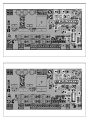 2
2
-
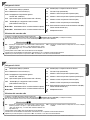 3
3
-
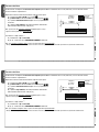 4
4
-
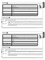 5
5
-
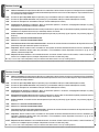 6
6
-
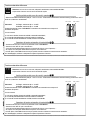 7
7
-
 8
8
-
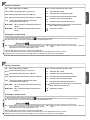 9
9
-
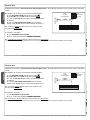 10
10
-
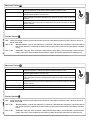 11
11
-
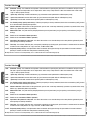 12
12
-
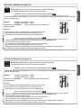 13
13
-
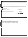 14
14
-
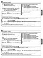 15
15
-
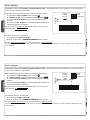 16
16
-
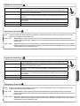 17
17
-
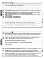 18
18
-
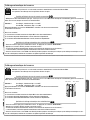 19
19
-
 20
20
-
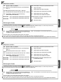 21
21
-
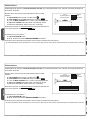 22
22
-
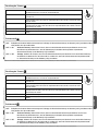 23
23
-
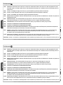 24
24
-
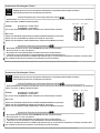 25
25
-
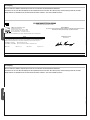 26
26
-
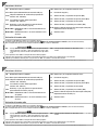 27
27
-
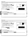 28
28
-
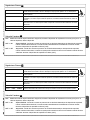 29
29
-
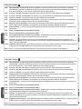 30
30
-
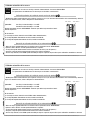 31
31
-
 32
32
-
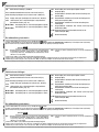 33
33
-
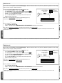 34
34
-
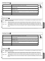 35
35
-
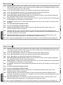 36
36
-
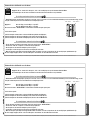 37
37
-
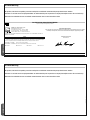 38
38
-
 39
39
-
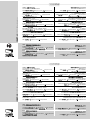 40
40


CAME 3199ZL90, 3199ZL90110 Spare Parts Manual
- Taper
- Spare Parts Manual
dans d''autres langues
- italiano: CAME 3199ZL90, 3199ZL90110
- English: CAME 3199ZL90, 3199ZL90110
- Deutsch: CAME 3199ZL90, 3199ZL90110
- Nederlands: CAME 3199ZL90, 3199ZL90110
Documents connexes
-
CAME ZL92 Guide d'installation
-
-
-
-
-
-
-
-
-
CAME ZL170N Manuel utilisateur