Scheppach MIX125 Manuel utilisateur

Taper
Manuel utilisateur
Art.Nr.
5908403901
5908403903
5908403850 | 02/2013
D
Betonmischer
Original-Anleitung
GB
Concrete mixer
Translation from the original instruction manual
FR
Bétonnière
Traduction du manuel d’origine
I
Betoniera
Vertaling van originele handleiding
SK
Miešačka betónu
Preklad originálneho návodu
CZ
Míchač betonové směsi
Překlad originálního návodu
MIX125
D
Betonmischer
Original-Anleitung
9
GB
Concrete mixer
Translation from the original instruction manual
14
FR
Bétonnière
Traduction du manuel d’origine
18
I
Betoniera
Vertaling van originele handleiding
23
SK
Miešačka betónu
Preklad originálneho návodu
28
CZ
Míchač betonové směsi
Překlad originálního návodu
33
Fig. 1
Fig. 2
Fig. 3
2
6
2
2
2
2
4
M8 70
M8 70
M8 65
M8 20
M8 16
M8 20
2
M8 25
1
M10 65
4
M8
1
42
Fig. 4
Fig. 5
Fig. 6
Fig. 7
Fig. 8
Fig. 9
Fig. 10
Fig. 11
Art.Nr.
590 8403 901
5908403850 | 09/2012
D
Betonmischer
Original-Anleitung
GB
Concrete mixer
Translation from the original instruction manual
FR
Bétonnière
Traduction du manuel d’origine
I
Betoniera
Vertaling van originele handleiding
MIX125
1
2
3
4
5
6
7
8
9
1011
12
13
4
Fig. 3
Fig. 4
2
M8 70
Fig. 5
2
M8 70
Fig. 6
Fig. 7
2
M8 65
142
2
M8 20
Fig. 8
Fig. 9
Fig. 10
F
2
M8 20
6
M8 16
2
M8 25
1
M10 65
Fig. 11
4
M8
Befüllposition
Filling position
Position de remplissage
Posizione di riempimento
Plniaca pozícia
Poloha pro plnění
Entleerung Position
Emptying position
Position de vidage
Svuotamento posizione
Vyprázdňovacia pozícia
Poloha pro vyprazdňování
Lager Position
Storage position
Position de rangement
Memorizzazione della posizione
Paměťová pozícia
Poloha pro skladování
Für Mörtel
For mortar
Pour le mortier
Per malta
pre malty
pro malty
Für Beton
For concrete
Pour le béton
Per calcestruzzo
pre betón
pro beton
Mischposition
Mixing position
Position de mélange
Posizione di miscelazione
Miešacia pozícia
Poloha pro míchání
Fig. 12
WIRING DIAGRAM
Save This Manual for Future Reference
Fig. 13
Allgemeine Hinweise
Wir wünschen Ihnen viel Freude und Erfolg
beim Arbeiten mit Ihrer neuen Maschine.
Hinweis:
Der Hersteller dieses Gerätes haftet nach
dem geltenden Produkthaftungsgesetz nicht
für Schäden, die an diesem Gerät oder durch
dieses Gerät entstehen bei:
unsachgemäßer Behandlung,
Nichtbeachtung der Bedienungsanweisung,
Reparaturen durch nicht autorisierte Fach-
kräfte,
Einbau und Austausch von nicht originalen
Ersatzteilen,
nicht bestimmungsgemäßer Verwendung,
Ausfällen der elektrischen Anlage bei
Nichtbeachtung der elektrischen Vorschrif-
ten und VDE-Bestimmungen 0100, DIN
57113 / VDE0113.
Wir empfehlen Ihnen:
Lesen Sie vor der Montage und vor Inbetrieb-
nahme den gesamten Text der Bedienungsan-
weisung durch. Diese Bedienungsanweisung
soll es Ihnen erleichtern, Ihre Maschine kennen
zu lernen und ihre bestimmungsgemäßen Ein-
satzmöglichkeiten zu nutzen.
Die Bedienungsanweisung enthält wichtige
Hinweise, wie Sie mit der Maschine sicher, fach-
gerecht und wirtschaftlich arbeiten, und wie Sie
Gefahren vermeiden, Reparaturkosten sparen,
Ausfallzeiten verringern und die Zuverlässigkeit
und Lebensdauer der Maschine erhöhen.
Zusätzlich zu den Sicherheitsbestimmungen
dieser Bedienungsanweisung müssen Sie unbe-
dingt die für den Betrieb der Maschine gelten-
den Vorschriften Ihres Landes beachten.
Die Bedienungsanweisung, in einer Plastikhülle
geschützt vor Schmutz und Feuchtigkeit, bei der
Maschine aufbewahren.
Sie muss von jeder Bedienungsperson vor
Aufnahme der Arbeit gelesen und sorgfältig be-
achtet werden. An der Maschine dürfen nur Per-
sonen arbeiten, die im Gebrauch der Maschine
unterwiesen und über die damit verbundenen
Gefahren unterrichtet sind. Das geforderte Min-
destalter ist einzuhalten.
Überpfen Sie nach dem Auspacken alle
Teile auf eventuelle Transportschäden. Bei
Beanstandungen muss sofort der Zubrin-
ger verständigt werden. Spätere Reklama-
tionen werden nicht anerkannt.
Überprüfen Sie die Sendung auf Vollstän-
digkeit.
Machen Sie sich vor dem Einsatz anhand
der Bedienungsanweisung mit dem Gerät
vertraut.
Verwenden Sie bei Zubehör sowie Ver-
schleiß- und Ersatzteilen nur Original-Teile.
Ersatzteile erhalten Sie bei Ihrem Fach-
händler.
Geben Sie bei Bestellungen unsere Arti-
kelnummern sowie Typ und Baujahr des
Gerätes an.
Allgemeine Sicherheitshinweise m
In dieser Bedienungsanweisung haben wir
Stellen, die Ihre Sicherheit betreffen, mit
diesem Zeichen versehen: m
WARNUNG: Wenn Sie Elektrowerkzeuge
verwenden, sollten Sie die nachstehenden
grundlegenden Sicherheitsvorkehrungen
befolgen, um so das Risiko von Feuer, elek-
trischem Schlag und Personenverletzungen
zu reduzieren.
Bitte lesen Sie alle Anweisungen, bevor sie
mit diesem Werkzeug arbeiten.
Alle Sicherheits- und Gefahrenhinweise an
der Maschine beachten.
Alle Sicherheits- und Gefahrenhinweise
an der Maschine vollzählig in lesbarem
Zustand halten.
Die Sicherheitseinrichtungen an der
Maschine dürfen nicht demontiert oder
unbrauchbar gemacht werden.
Netzanschlussleitungen überprüfen. Keine
fehlerhaften Anschlussleitungen verwen-
den.
Vor Inbetriebnahme die korrekte Funktion
prüfen.
Die Bedienungsperson muss mindestens
18 Jahre alt sein. Auszubildende müs-
sen mindestens 16 Jahre alt sein, dürfen
aber nur unter Aufsicht an der Maschine
arbeiten.
Personen die unter Alkohol-, Drogen -
Medikamenteneinuss stehen ist der
Gebrauch nicht gestattet.
Beim Arbeiten Arbeitshandschuhe tragen.
Vorsicht beim Arbeiten: Verletzungsgefahr
durch rotierende Teile
Wartungsarbeiten und Beheben von
Störungen nur bei ausgeschaltetem Motor
durchführen. Netzstecker ziehen!
Installationen, Reparaturen und Wartungs-
arbeiten an der Elektroinstallation dürfen
nur von Fachkräften ausgeführt werden.
Sämtliche Schutz -und Sicherheitseinrich-
tungen müssen nach abgeschlossenen
Reparatur- und Wartungsarbeiten sofort
wieder montiert werden.
Beim Verlassen des Arbeitsplatzes den
Motor ausschalten. Netzstecker ziehen!
Achten sie auf eine ausreichende Beleuch-
tung
Im Gefahrenfall Maschine ausschalten und
Netzstecker ziehen!
Niemals bei eingeschalteter Maschine
die Hände auf sich bewegende Teile der
Maschine legen.
Zusätzliche Sicherheitshinweise für Betonmischer m
Der Betonmischer darf nur vollständig mon-
tiert in Betrieb genommen werden.
Die Anschlussleitungen vor Inbetriebnahme
auf Beschädigungen überprüfen.
Sicherheitsschuhe, Handschuhe, Schutz-
brille und Atemschutzmaske tragen.
Hände und Füße von beweglichen Teilen
fernhalten.
Nicht in die laufende Mischtrommel greifen.
Keine Gegenstände in die laufende
Mischtrommel stecken z.B. Schaufel oder
ähnliches.
Verletzungsgefahr bei drehender Misch-
trommel.
Betonmischer darf nur mit Original- Ersatz-
teilen betrieben werden.
Reparaturen am Betonmischer dürfen nur
durch autorisierte Fachbetriebe durchge-
führt werden.
Betriebsbereiten Betonmischer nicht unbe-
aufsichtigt lassen.
Beim Verlassen des Arbeitsplatzes Maschi-
ne ausschalten und Netzstecker ziehen.
Symbole m
Vor Inbetriebnahme das Bedienungsanweisung lesen!
Betonmischer waagerecht auf ebenen und festen Boden
stellen!
Betonmischer darf im Betrieb nicht bewegt werden!
Nicht autorisierte Personen und Kinder vom Gerät fern
halten!
9
D
Das Gerät ist schutzisoliert!
Achtung!
Die Schutzklasse bleibt nur erhalten, wenn im Servicefall
Originalisolierstoffe verwendet werden und die Isolationsab-
stände nicht verändert werden.
Vor Reinigung oder Wartung Netzstecker ziehen!
Size: 20 (mm) 40 (mm)
Ø 25 mm
129 x 70
Betonmischer darf nur mit vollständig geschlossener
Schutzeinrichtung betrieben werden!
Schutzkleidung tragen!
Nicht in die sich bewegende Trommel greifen!
Vorsicht!
Quetschgefahr am Zahnkranz
Montagehilfe!
Siehe: Montage, Trommeloberteil montieren (Fig.6)
Bestimmungsgemäße Verwendung m
Die Maschine entspricht der gültigen EG
Maschinenrichtlinie.
Der Betonmischer ist nur für den privaten
Gebrauch in Haus und Garten bestimmt.
Er darf nur im Rahmen der technischen
Daten betrieben werden.
Der Betonmischer ist ausschließlich zur
Herstellung von Beton und Mörtel be-
stimmt.
Die zutreffenden Unfallverhütungsvorschrif-
ten und die sonstigen allgemein anerkann-
ten sicherheitstechnischen Regeln müssen
beachtet werden.
Die Maschine darf nur von Personen ge-
nutzt, gewartet oder repariert werden, die
damit vertraut und über die Gefahren unter-
richtet sind. Eigenmächtige Veränderungen
an der Maschine schließen eine Haftung
des Herstellers für daraus resultierende
Schäden aus.
Die Maschine darf nur mit Originalzubehör
und Original-Werkzeugen des Herstellers
genutzt werden.
Jeder darüber hinausgehende Gebrauch
gilt als nicht bestimmungsgemäß. Für
daraus resultierende Schäden haftet der
Hersteller nicht; das Risiko dafür trägt allein
der Benutzer.
Achtung! Es ist nicht gestattet:
Der Betrieb in Explosionsgefährdender
Atmosphäre
Der Einsatz im Lebensmittelgewerbe
Das Mischen von explosiven, brennbaren
und gesundheitsscdlichen Stoffen.
Restrisiken m
Die Maschine ist nach dem Stand der Tech-
nik und den anerkannten Sicherheitstechni-
schen Regeln gebaut. Dennoch können beim
Arbeiten einzelne Restrisiken auftreten.
Verletzungsgefahr durch rotierende Teile.
Gefährdung durch Strom bei Verwendung
nicht ordnungsgemäßer Elektroanschluss-
leitungen
Des Weiteren können trotz aller getroffener
Vorkehrungen nicht offensichtliche Restrisi-
ken bestehen.
Restrisiken können minimiert werden, wenn
die Sicherheitshinweise und die Bestim-
mungsgemäße Verwendung, sowie die
Bedienungsanweisung beachtet werden.
Elektrischer Anschluss m
Der installierte Elektromotor ist betriebsfertig
angeschlossen. Der Anschluss entspricht den
einschlägigen VDE- und DIN Bestimmungen.
Der kundenseitige Netzanschluss sowie die ver-
wendete Verlängerungsleitung müssen diesen
Vorschriften entsprechen.
Wichtige Hinweise
Bei Überlastung des Motors schaltet dieser
Selbsttätig ab.
Nach einer Abkühlzeit (zeitlich unterschiedlich)
lässt sich der Motor wieder einschalten.
Schadhafte Elektro-Anschlussleitungen
An elektrischen Anschlussleitungen entstehen
oft Isolationsschäden.
Ursachen sind:
Druckstellen, wenn Anschlussleitungen
durch Fenster oder Türspalten geführt
werden.
Knickstellen, durch unsachgemäße Befes-
tigung oder Führung der Anschlussleitun-
gen.
Schnittstellen durch Überfahren der An-
schlussleitungen.
Isolationsschäden durch Herausreißen aus
der Wandsteckdose.
Risse durch Alterung der Isolation. Solche
schadhaften Elektro-Anschlussleitungen
dürfen nicht verwendet werden und sind
auf Grund der Isolationsschäden lebens-
gefährlich!
Elektrische Anschlussleitungen regelmäßig auf
Schäden überpfen. Achten Sie darauf, dass
beim Überprüfen die Anschlussleitung nicht
am Stromnetz hängt. Elektrische Anschlusslei-
tungen müssen den einschlägigen VDE- und
DIN-Bestimmungen entsprechen. Verwenden
Sie nur Anschlussleitungen mit Kennzeichnung
H 07 RN.
Ein Aufdruck der Typenbezeichnung auf der
Anschlussleitung ist Vorschrift.
Wechselstrommotor
Wechselstrommotor 230 V/ 50 Hz, Netzspan-
nung 230 Volt / 50 Hz.
Die Verwendung einer Fehlerstrom-Schutzein-
richtung („FI“) wird bei einem 230V Anschluss
empfohlen. Wenn Sie ein Verlängerungskabel
verwenden, stecken Sie es direkt in den FI.
Beim Betrieb in der Schweiz, stecken Sie den
Betonmischer nur in Steckdosen, die durch ei-
nen Fehlerstrom-Schutzschalter geschützt sind.
Netzanschluss und Verlängerungsleitung kön-
nen sowohl 3-, als auch 2-adrig sein.
3-Adrig: P + N + SL. - (1/N/PE); 2-Adrig: P +
N – (1/N)
Verlängerungsleitungen müssen einen Mindest-
querschnitt von 1,5 mm² aufweisen.
Anschlussleitung, Stecker und Kupplungsdose
müssen spritzwassergeschützt sein.
Der Netzanschluss wird mit maximal 16A abge-
sichert.
Anschsse und Reparaturen an der Elek-
trischen Ausrüstung dürfen nur von einer
Elektro- Fachkraft durchgeführt werden.
D
10
Bei Rückfragen bitte folgende Daten ange-
ben.
Stromart des Motors.
Daten des Maschinen- Typschildes.
Bei Rücksendung des Motors immer die kom-
plette Antriebseinheit mit Schalter einsenden.
Ausstattung Packliste Fig.1
1. Standfuß vorn
2. Motorgehäuse
3. Rahmen
4. Schwenkrad
5. Trommel-Oberteil
6. Lagerhalterung
7. Trommel-Unterteil
8. Anleitung
9. Mischwerk
10. Beipackbeutel (Fig. 2 Inhalt)
11. Standfuß hinten mit Radachse
12. 2 Räder
13. Rasterscheibe
Technische Daten
Motor ..........................................................................................................................230V / 50 Hz 0,55 kW
Fassungsvolumen ..................................................................................................................................125 l
Schutzklasse ......................................................................................................................................IP 45D
(IP=International Protection; 4=Schutz geg. Berührung m. Draht d=1mm + Schutz geg. Eindringen von Fremdkörpern d/=1mm; 5=Schutz gegen Wasserstrahl aus allen Richtungen; D=Schutz geg. Berührung mit Draht d=1mm 100 mm lang)
Abmessung ................................................................................................... 1200mm x 710mm x 1400mm
Gewicht .................................................................................................................................................50 kg
Information zur Geräuschentwicklung
Die Geräuschpegel dieser Maschine während
des Betriebs sind die folgenden:
L
pA
: 73,2dB(A) K=3dB(A)
L
wA
: 93dB(A) K=3dB(A)
Vibration: 4.51m/s
2
K=1.5m/s
2
Warnung: Lärm kann gravierende Auswirkun-
gen auf Ihre Gesundheit haben. Übersteigt der
Maschinenlärm 85 dB (A), tragen Sie bitte einen
geeigneten Gehörschutz. Falls der elektrische
Anschluss defekt ist, kann der Strom beim Start
der Maschine abfallen. Dies kann andere Maschi-
nen beeinträchtigen (z. B. blinkende Lampen).
Entspricht die elektrische Leistung Zmax < 0,27,
solten solche Störungen nicht auftreten. (Falls
doch, informieren Sie Ihren Fachhändler).
Der angegebene Schwingungsemissionswert
ist nach einem genormten Prüfverfahren
gemessen worden und kann zum Vergleich
eines Elektrowerkzeugs mit einem anderen
verwendet werden;
Der angegebene Schwingungsemissionswert
kann auch zu einer ersten Beurteilung der
Belastung verwendet werden.
Warnung:
Der Schwingungsemissionswert kann sich
während der tatsächlichen Benutzung des
Elektrowerkzeugs von dem Angabewert
unterscheiden, abhängig von der Art und
Weise, in der das Elektrowerkzeug verwendet
wird;
Versuchen Sie, die Belastung durch
Vibrationen so gering wie möglich zu halten.
Beispielhafte Maßnahmen zur Verringerung
der Vibrationsbelastung sind das Tragen von
Handschuhen beim Gebrauch des Werkzeugs
und die Begrenzung der Arbeitszeit. Dabei
sind alle Anteile des Betriebszyklus sind zu
berücksichtigen (beispielsweise Zeiten, in
denen das Elektrowerkzeug abgeschaltet ist,
und solche, in denen es zwar eingeschaltet ist,
aber ohne Belastung läuft).
Auspacken
Betonmischer mit zwei Personen aus dem Karton nehmen.
Überprüfen Sie den Inhalt auf Vollständigkeit.
Bei Mängeln Händler informieren.
Montage
Achtung!
Der Betonmischer darf erst nach kompletter
Montage benutzt werden.
1. Räder montieren Fig.3
An Standfuß hinten mit Radachse (11), beid-
seitig Splint, Scheibe, Rad (12), Scheibe, Splint
montieren.
Splinte nach dem montieren leicht aufbiegen
2. Standfuß vorn mit Rahmen montieren
Fig.4
Standfuß vorn (1) mit 2 Schrauben M8x70, 2
Scheiben 8mm, 2 Federringe, 2 Muttern M8 an
Rahmen (3) montieren und fest anziehen.
3. Rahmen mit Radstütze montieren Fig. 5
Rahmen und Radstütze kpl. mit 2 Sechs-
kantschrauben M8x70, 2 Scheiben 8mm, 2Fe-
derringe, 2 Muttern M8 montieren. Schrauben
fest anziehen.
4. Trommelunterteil mit Rahmen montieren
Fig.6
Trommelunterteil(7) mit Lagerhalterung(6) auf
Vormontiertes Gestell setzen, mit 2 Sechs-
kantschrauben M8x65, 2 Scheiben, 2 Federrin-
ge und 2 Muttern M8 festziehen.
Mit Spiralring Ø42 sichern.
5. Mischwerk montieren Fig.7
Mischwerk (9) mit 2 Kreuzschlitzschrauben
M8x20 an Trommelunterteil mit 2 Scheiben, 2
Federringe und 2 Muttern M8 sichern. Zwischen
Mischwerk und Trommel je eine Gummischeibe
einlegen.
6. Trommeloberteil montieren Fig.8
Gummiring auf das Unterteil legen. Tromme-
loberteil aufsetzen.
Achtung! Die aufgeklebten Pfeile markieren
die exakte Ausrichtung des Trommelunter und
-oberteils. Trommeloberteil ausrichten und mit
6 Kreuzschlitzschrauben M8x16, an Trommel-
unterteil montieren und festziehen. Mischwerk
(9) mit 2 Kreuzschlitzschrauben M8x20, 2
Sicherungsscheiben an Trommelunterteil mit
2 Scheiben, 2 Federringe und 2 Muttern M8
sichern. Zwischen Mischwerk und Trommel je
eine Gummischeibe einlegen.
7. Rasterscheibe montieren Fig.9
Rasterscheibe (13) mit 2 Sechskantschrauben
M8x25, 2 Scheiben, 2 Federringe an Schwenk-
achse montieren und festziehen.
8. Schwenkrad montieren. Fig.10
Die Feder des Schwenkrades ist für die leichtere
Montage mittels eines U-Bleches gesichert.
Schwenkrad (4) auf Schwenkachse schieben mit
Sechskantschraube M10x65, Scheibe, Scheibe
und Selbstsichernde Mutter M10 sichern. U-
Blech entfernen.
9. Motorgehäuse montieren. Fig.11
Motorgehäuse auf die Halteplatte setzen, mit 4
Sicherheitsmuttern M8 sichern.
11
D
Betrieb
Betreiben Sie den Betonmischer nur, wenn
keine Teile (z.B. Schutzabdeckungen) fehlen
oder defekt sind und wenn die Anschlusslei-
tung keine Beschädigung aufweist.
Aufstellen:
Stellen Sie den Betonmischer waagrecht
auf ebenen, festen Untergrund.
Stellen Sie den Betonmischer nicht auf die
Anschlussleitung!
Verlegen Sie die Anschlussleitung so, dass
diese nicht geknickt, gequetscht oder auf
andere Weise beschädigt werden kann.
Hinweis:
Die Trommel muss nach rechts und links
schwenkbar sein. Zum Entleeren der Trom-
mel muss unter der Trommel Platz für eine
Schubkarre sein.
Einschalten:
Stecken Sie das Gerät an Steckdose ein
Einschalten auf „I“ (Gne Taste) / Aus-
schalten auf „0“ (Rote Taste)
Verstellen der Trommel (Fig. 12):
Zum Verstellen der Trommel müssen Sie
das seitliche Handrad zurückziehen, so-
dass Sie die Trommel bewegen können.
Bendet sich die Trommel in der gewünsch-
ten Position, rasten Sie das Handrad
wieder ein.
Befüllen
Achten Sie vor dem Befüllen darauf, dass
die Öffnung der Trommel so ausgerichtet
ist, dass kein Mischgut aus der Trommel
herausfallen kann. (Fig. 13)
Füllen Sie das Mischgut bei laufender
Trommel ein (Überfüllen Sie die Trommel
nicht)
Vorsicht! Gefahr vor bewegten Teilen
Entleeren
Schwenken Sie zum Entleeren der Trommel
diese nach unten
Achten Sie darauf, dass unter der Trommel
ein ausreichendes Behältnis (z.B. Schub-
karren) bereitsteht.
Achten Sie darauf, dass kein Mischgut auf
den Boden gelangen kann
Transport
Achtung!
Vor jedem Transport Netzstecker ziehen.
1. Einfüllöffnung nach unten stellen.
2. Beim Transport mit einem Fahrzeug Schrauben entfernen und Füße einklappen.
3. Mischer mit Spanngurt gegen Verschiebungen sichern
4. Betonmischer nicht mit dem Kran anheben
Wartung
Achtung!
Bei allen Arbeiten oder Reparaturen am Beton-
mischer:
Betonmischer ausschalten, Stillstand der
Trommel abwarten und Netzstecker ziehen.
Reparaturen dürfen nur durch autorisierte Fach-
kräfte durchgeführt werden.
Vor jedem Einsatz des Betonmischers, Sicht-
kontrolle vornehmen.
Sämtliche Sicherheitsteile müssen montiert
sein.
Defekte Anschlussleitungen dürfen nicht ver-
wendet werden
Reinigung
Achtung! Maschine ausschalten Stillstand
der Trommel abwarten und Netzstecker
ziehen.
Nach jedem Gebrauch des Betonmischers
Trommel mit Wasser reinigen.
Zement und Mörtelkruste entfernen. Motorge-
häuse und Trommel nicht mit einer Schaufel
oder einem anderen harten Gegenständen
abklopfen, da diese sonst beschädigt werden
können.
Riemenspannung prüfen/nachstellen
Achtung! Maschine ausschalten Stillstand
der Trommel abwarten und Netzstecker
ziehen.
Abdeckung des Motorgehäuses entfernen,
Riemenspannung prüfen (durch Druck mit
dem Finger auf den Riemen, sollte der
Riemen ca. 5mm nachgeben.)
Riemen sind Verschleißteile die nach einer
bestimmten Zeit ausgetauscht werden
müssen. Bei Bedarf Schrauben am Motor
lösen, Riemen tauschen, auf Spannung
bringen und Schrauben wieder anziehen.
Motorabdeckung wieder montieren.
Störungsabhilfe
Störung Mögliche Ursache Abhilfe
Motor schaltet ab Motor überlastet Motor abkühlen lassen
Motor läuft, Trommel bleibt stehen Keilriemen rutscht durch Keilriemen tauschen
Bei sonstigen Störungen Betonmischer ausschalten, Netzstecker ziehen und Störung von einem autorisierten Fachbetrieb beheben lassen
D
12
Abbau und Entsorgung
Die Maschine enthält keine gesundheits- oder
umweltschädlichen Stoffe, da sie aus völlig wie-
derverwertbaren oder auf normalem Wege
zu entsorgenden Materialien gebaut wurde.
Zur Entsorgung sollte man sich an Spezialrmen
oder an qualiziertes Fachpersonal wenden, das
die möglichen Risiken kennt, die vorliegenden
Gebrauchsanweisungen gelesen hat und genau
befolgt. Wenn die Maschine ausgedient hat,
geht man unter Beachtung aller angegebenen
Unfallverhütungsnormen folgendermaßen vor:
die Energiezufuhr unterbrechen (elektrisch
oder PTO),
alle Stromkabel entfernen und an eine
spezialisierte Sammelstelle übergeben,
indem man die jeweils im Lande geltenden
Bestimmungen befolgt.
Alle übrigen Maschinenteile an eine
Schrottsammelstelle abgeben, indem man
die jeweils im Lande geltenden Bestimmun-
gen befolgt.
Darauf achten, dass jedes Maschinenteil ent-
sorgt wird, indem man die jeweils im Lande
geltenden Bestimmungen befolgt.
13
D
General instructions
We wish you lots of fun and success whilst
working with your new machine.
Note:
According to the applicable Product Liability
Law, the manufacturer of this machine is not
liable for damages that occur at this machine or
on account of this machine attributable to:
Improper handling,
Non-observation of the operating instruc-
tions,
Repairs by unauthorised technicians,
Installation or replacement of spare parts
that are not original,
Improper use,
Failure of electrical system, due to non-
observation of electrical specications
and VDE provisions 0100, DIN 57113 /
VDE0113.
We recommend the following:
Please read the entire text of the operating
instructions before installation and start-up.
These operating instructions will enable you to
get to know your machine better and to exploit
the options for its proper use.
The operating instructions contain important
instructions on how you can work with your ma-
chine safely, professionally and economically,
and how you can avoid risks, save repair costs,
reduce downtimes and increase the reliability
and life span of the machine.
In addition to the safety provisions of these
operating instructions, you must also observe
without fail, the applicable specications of your
country, for the operation of the machine.
Keep the operating instructions in a plastic
cover near the machine, protected against dirt
and humidity.
The instructions must be read by every member
of the operating staff before starting work and
then observed carefully. Only persons who are
trained to use the machine, and instructed about
the risks associated with it, should operate
it. The minimum age requirements must be
observed.
After unpacking, check all parts for possible
transport damage. In the case ofcomp-
laints, the distributor must be contacted
immediately. Complaints will not be enter-
tained later.
Check to ensure that the delivery is com-
plete.
Familiarise yourself with the machine befo-
re using it, by referring to the operatingin-
structions.
For accessories as well as parts and spa-
res, please use only original parts. Spare
parts can be obtained from your specialist
dealer.
In your orders, please quote our article
Nos. as well as the type and year of manu-
facture of the machine.
General safety instructions m
We have marked the positions that affect
your safety in the operation instructions
with this sign: m
WARNING: If you use electrical tools, please
comply with the basic safety-related preven-
tive measures given below so as to minimize
the risk of re, electric shock and physical
injuries.
Please read all the instructions before star-
ting work with this tool.
All safety- and risk-related instructions on
the machine must be observed.
All safety- and risk-related instructions on
the machine must be kept near to the ma-
chine in complete and readable condition.
The safety devices on the machine are not
to be dismantled or disabled.
Check the mains power cables. Do not use
faulty connecting cables.
Check the correct functioning before start-
up.
The operator must be a minimum of 18
years old. Trainees must be a minimum of
16 years old; however they may work at
the machine only under supervision.
Persons under the inuence of alcohol,
drugs or medicine are not allowed to use
the machine.
Wear working gloves when working.
Exercise caution during work: risk of injury
from rotating parts
Maintenance jobs and troubleshooting
should be performed only after switching
the motor off. Pull out the power plug!
Only electricians should be allowed to per-
form installation, repair and servicing jobs
on the electrical installations.
All protection and safety devices must be
reactivated after the repair and servicing
jobs have been completed.
Switch the motor off when leaving the work-
place. Pull out the power plug!
Ensure that there is adequate illumination.
In case of danger, switch off the machine
and pull out the power plug!
Never put your hands on moving parts of
the machine, when the machine is inope-
ration.
Additional safety instructions for concrete mixers m
The concrete mixer should be commissi-
oned only after it is fully installed.
Check the connecting cables for damage
before start-up.
Wear safety shoes, gloves, protective glas-
ses and respirator masks.
Keep hands and feet away from moving
parts.
Do not put your hands into the running
mixing drum.
Do not insert any object into the running
mixing drum e.g., shovel etc.
Risk of physical injury when mixing drum is
rotating.
The concrete mixer should be operated
only with original spare parts.
Repairs on the concrete mixer should be
performed only by authorised technicians.
Do not leave an operation-ready concrete
mixer without supervision.
Switch the machine off and pull the power
plug out before leaving the workplace.
Symbols m
Read the operating instructions before start-up!
Place the concrete mixer horizontally on even and rm
ground!
The concrete mixer should not be moved when in operation!
Keep unauthorised persons and children away from the
device!
14
DGB
The machine has protective insulation!
Caution!
The protection class is retained only if original insulating
material is used during maintenance and the insulation dis-
tances are not changed.
Pull the power plug out before cleaning or maintenance!
Size: 20 (mm) 40 (mm)
Ø 25 mm
129 x 70
The concrete mixer can be operated only with fully closed
protection device!
Wear protective clothes!
Do not put your hands into the moving drum!
Caution!
Risk of getting crushed at the sprocket
Installation help!
See: Installation, installing the upper section of the drum
(Fig.6)
Correct use according to manufacturer´s instructions m
The machine corresponds to the applicable
EC Machine Directive.
The concrete mixer is intended exclusively
for private use at home and in the garden.
It should be operated only within the frame-
work of the technical data.
The concrete mixer is meant exclusively for
the production of concrete and mortar.
The applicable accident prevention rules
and the other generally recognised techni-
cal safety regulations must be observed.
The machine may be used, serviced or
repaired only by persons who are familiar
with it and are instructed about its risks.
Arbitrary alterations in the machine will free
the manufacturer from any liability for the
resulting damage.
The machine is to be used only with the
manufacturers original accessories and
original tools.
Any use that goes beyond this will be
treated as improper use. The manufacturer
will not be responsible for damage resulting
from improper use; the risk will be borne
solely by the user.
Caution! The Following Actions are Forbid-
den:
Operation in atmosphere that is exposed to
the risk of explosion
Use in the food products industry
Mixing explosive, combustible and health-
endangering substances.
Residual risks m
The machine is built on the basis of the
latest technology and in accordance with the
recognised technical safety rules. Never-
theless, individual residual risks can occur
while working.
Risk of injury from rotating parts
Risk from power where improper electrical
connecting cables are used
Further, indeterminate residual risks may
remain even after taking all relevant pre-
ventive measures.
Residual risks can be minimised if the sa-
fety instructions and conditions for proper
use, as well as the operating instructions,
are observed
Electrical connection m
The installed electric motor is connected in
operation-ready condition. The connection
corresponds to the common VDE and DIN
provisions.
The customer-side mains connection, as well as
the used extension cable, must correspond to
these specications.
Important Instructions
In case of overload, the motor is switched off
automatically.
The motor can be activated again after a
cooling period (different times for different
models).
Damaged Electrical Connecting Cables
Electrical connecting cables frequently experi-
ence insulation damage.
The causes are:
Pressure points, if connecting cables are
routed through windows or doors.
Kinks, due to improper mounting or routing
of the connecting cables.
Cuts due to connecting cables being run
over.
Insulation damages due to tearing away
from the wall socket.
Cracks in insulation due to ageing. Such
damaged electrical connecting cables
should not be used, they can be fatal due to
damaged insulation!
Check electrical connecting cables regularly
for damage. Ensure that when checking the
connecting cable, it does not hang from the
power mains. Electrical connecting cables must
correspond to the common VDE and DIN provi-
sions. Use only connecting cables that have the
designation H 07 RN.
An imprint of the type designation on the con-
necting cable is mandatory.
AC Motor
AC motor 230 V/ 50 Hz, mains voltage 230 Volt
/ 50 Hz.
Use of a residual current protection device (FI“)
is recommended for a 230V connection. If you
use an extension cable, insert it directly into the
FI.
15
DGB
If operating it in Switzerland, insert the concrete
mixer only in sockets that are protected by a
residual current-operated circuit breaker.
Mains connection and extension cable can have
3 wires as well as 2.
3-wire: P + N + SL. - (1/N/PE); 2-wire: P + N –
(1/N)
Extension cables must have a minimum cross-
section of 1.5 mm².
Connecting cable, plug and coupling jack must
be protected against water spray.
The mains connection is protected with a maxi-
mum 16A fuse.
Connections and repairs of the electrical
equipment should be performed by electri-
cians only.
Please quote the following information in
your queries:
Current type of the motor.
Data on the machine ratings plate.
When returning the motor, always send the
complete drive unit with switch.
Equipment packing list Fig.1
1. Supporting stand, front
2. Motor casing
3. Frame
4. Swivel wheel
5. Drum upper section
6. Bearing bracket
7. Drum lower section
8. Instructions
9. Mixer
10. Bag provided (Fig. 2 Content)
11. Supporting stand, rear with wheel axle
12. 2 wheels
13. Locking washer
Technical data
Motor ..........................................................................................................................230V / 50 Hz 0,55 kW
Capacity .................................................................................................................................................125 l
Protection class .................................................................................................................................. IP 45D
(IP=International Protection; 4=Protection against contact with wire d=1mm+Protection against ingress of foreign bodies d>/= 1mm; 5=Protection against water jets from all directions; D=Protection against contact with wire d=1mm, 100mm
long)
Dimensions ................................................................................................... 1200mm x 710mm x 1400mm
Weight ...................................................................................................................................................50 kg
Information on noise
The noise levels of the machine during operation
are as follows:
L
pA
: 73,2dB(A) K=3dB(A)
L
wA
: 93dB(A) K=3dB(A)
Vibration: 4.51m/s
2
K=1.5m/s
2
Warning: Noise can seriously damage your
health. If the engine noise exceeds 85 dB (A),
please wear appropriate hearing protection. If
the electrical connection is faulty, the current may
drop when the machine starts. This may affect
other machines (e.g. ashing lights). If the elec-
tric output corresponds to Zmax <0.27, such in-
terference should not occur. (If it does, notify your
dealer).
The vibration emission value given below has
been measured by a standardized test, and
can be used for comparing one power tool to
another;
The vibration emission value given below
may also be used for a rst assessment of
exposure.
Warning:
The vibration emission value may vary during
actual use of the power tool from the specied
value, depending on the manner in which the
power tool is used;
Try to keep exposure to vibration to a minimum.
Examples of ways to reduce vibration levels
are wearing gloves when using the tool and
limiting working hours. In doing so, all parts of
the operating cycle must be taken into account
(for example, times in which the power tool is
turned off, or when it is turned on without load).
Unpacking
Take the concrete mixer out of the carton with
the help of two persons.
Check to ensure that the delivery is complete.
Inform the dealer if there are faults.
Montage
Caution!
The concrete mixer should be used only after it
is installed fully.
1. Installing wheels Fig.3
Install splint on both sides, washer, wheel (12),
washer, splint on the supporting stand rear with
wheel axle (11).
Bend the splints slightly after installation
2. Installing the front supporting stand with
frame Fig.4
Install front supporting stand (1) with 2 M8x70
screws, 2 8mm washers, 2 lockwashers, 2 M8
nuts on the frame (3) and tighten the screws.
3. Installing the frame with the wheel sup-
ports Fig. 5
Install frame and wheel supports fully with 2
M8x70 hexagon bolts, 2 8mm washers, 2 lock-
washers and 2 M8 nuts. Tighten the screws.
4. Installing the lower section of drum with
frame Fig.6
Set the lower section of the drum (7) with bea-
ring bracket (6) on the pre-installed framework,
tighten with 2 M8x65 hexagon bolts, 2 washers,
2 lockwashers and 2 M8 nuts.
Secure with a Ø42 spiral ring.
5. Installing mixer Fig.7
Lock mixer (9) with 2 M8x20 cross-head screws
to the lower section of the drum with 2 washers,
2 lockwashers and 2 M8 nuts. Insert one rubber
washer each between mixer and drum.
6. Installing upper section of drum Fig.8
Place rubber ring on the lower section. Place the
upper section of drum on it.
Caution! The pasted arrows mark the exact di-
rection of the upper or lower section of the drum.
Align the upper section of the drum and install
it on the lower section with 6 M8x16 cross-head
screws and tighten. Lock mixer (9) with 2 M8x20
cross-head screws and 2 lockwashers to the
lower section of the drum with 2 washers, 2
lockwashers and 2 M8 nuts. Insert one rubber
washer each between mixer and drum.
7. Installing lockwasher Fig.9
Install lockwasher (13) with 2 M8x25 hexagon
bolts, 2 washers, 2 lockwashers on the swivel
axis and tighten.
8. Installing swivel wheel. Fig.10
The spring of the swivel wheel is locked to facili-
tate installation with the help of a U-sheet. Slide
swivel wheel (4) onto the swivel axis and secure
with M10x65 hexagon bolt, washer, washer and
self-locking M10 nuts. Remove U-sheet.
9. Installing motor casing. Fig.11
Place the motor casing on the retaining plate,
secure with 4 M8 safety nuts.
16
DGB
Operation
Operate the concrete mixer only if no parts
(e.g., safety covers) are missing or defective,
and the connecting cable is not damaged.
Set up:
Place the concrete mixer horizontally on
even, rm ground.
Do not place it on the connecting cable!
Route the connecting cable in a manner,
such that it cannot be kinked, crushed or
damaged in some other way.
Note:
It should be possible to swivel the drum to
the right and left. There must be sufcient
space for a wheelbarrow under the drum, so
that it can be emptied.
Activation:
Plug the device into the socket Activation
on “I” (green button) / Deactivation on
“0” (red button)
Moving the drum (Fig. 12):
To move the drum, pull back the hand
wheel so that the drum can be moved.
When the drum is in the desired position,
lock the hand wheel again.
Filling
Before lling the drum, ensure that the
opening is aligned in such a way that the
mixture cannot fall out of the drum. (Fig.
13)
Put the mixture in when the drum is rotating
(do not overll the drum)
Caution! Risk of moving parts
Emptying
Swivel the drum in the downward direction
to empty it
Ensure that there is an adequate container
under the drum (e.g., wheelbarrow).
Ensure that no mixture falls on the ground
Transport
Caution!
Pull the power plug out, every time, before transporting the machine.
1. Set the lling opening downwards.
2. During transportation by motor vehicle, remove the screws and fold the stands.
3. Lock the mixer with a strap to prevent displacement
4. Do not lift the concrete mixer with the help of a crane
Maintenance
Caution!
While working with the concrete mixer or perfor-
ming repairs on it, please do the following:
Switch off the concrete mixer, wait for the drum
to come to a standstill and pull out the pow-
er plug.
Repairs on the concrete mixer should be perfor-
med only by authorised technicians.
Perform visual inspection before each use of the
concrete mixer.
All safety parts must be installed.
Defective connecting cables should not be used.
Cleaning
Caution! Switch off the machine, wait for the
drum to come to a standstill and pull out the
power plug.
Clean the drum with water after each use of the
concrete mixer.
Remove cement and mortar residues. Do not
tap motor casing and drum with a shovel or any
other hard object, as these can be damaged.
Checking/re- adjusting belt tension
Caution! Switch off the machine, wait for the
drum to come to a standstill and pull out the
power plug.
Remove the cover of the motor casing,
check the belt tension (on pressing the belt
with the nger, it should yield by approx.
5mm.)
Belts are wear and tear parts that must be
replaced after a certain period. If necessa-
ry, detach the screws on the motor, replace
the belt, adjust the correct tension and
tighten the screws again.
Reinstall the motor cover.
Troubleshooting
Fault Possible cause Remedy
Motor switches off Motor is overloaded Let motor cool down
Motor runs, drum does not move V-belt skids through Replace V-belt
Switch off the concrete mixer if such faults occur, pull out the power plug and get the fault rectied by an authorised professional company
Dismantling and disposal
The machine does not contain any substances
that are hazardous to health or harmful for the
environment, as it was produced entirely from
recyclable materials or materials that can be
disposed through normal means.
For disposal, please contact a specialist com-
pany or a qualied professional who knows the
possible risks, has read these instructions for
use, and follows them scrupulously. If the ma-
chine has served its time, please comply with all
the specied accident prevention standards, and
proceed as follows:
Disconnect the energy supply (electrical or
PTO),
Remove all power cables and deposit them
at a specialist location, in accordance
with the applicable country-specic legal
provisions.
Put all the remaining machine parts at a
scrap collection location, in accordance
with the applicable country-specic legal
provisions.
Ensure that each machine part is disposed
of in accordance with the relevant applicable
country-specic legal provisions.
17
DGB
F
18
Consignes générales
Nous espérons que vous travaillerez avec
plaisir et selon vos exigences sur votre nouvelle
machine.
Consigne :
Conforment à la loi en vigueur sur la respon-
sabilité du fait des produits, le fabricant de cet
appareil n‘est pas responsable des dommages
survenus sur l‘appareil ou générés sur l‘appareil
en cas de :
manipulation incorrecte,
inobservation de la notice d‘utilisation,
réparations effectuées par des spécialistes
non autorisés,
montage et remplacement des pièces de
rechange non originales,
utilisation non conforme,
pannes de l‘installation électrique
L‘inobservation des prescriptions élec-
triques et des dispositions de la VDE 0100,
DIN 57113 / VDE0113.
Nos recommandations sont les suivantes :
Lisez l‘ensemble du texte de la notice
d‘utilisation avant le montage et la mise en
service. Cette notice d‘utilisation vous permet
de faciliter la découverte de votre machine et
d‘exploiter conformément aux dispositions ses
possibilités d‘utilisation.
La notice d‘utilisation contient des consignes
importantes sur la manière de travailler en toute
sécurité, réglementairement et économique-
ment avec la machine, et sur la fon d‘éviter
les dangers, économiser les coûts de réparati-
on, réduire les périodes d‘arrêt et augmenter la
abilité et la durée de vie de la machine.
Outre les dispositions de sécurité de cette noti-
ce d‘utilisation, vous devez absolument obser-
ver les prescriptions de votre pays en vigueur
pour le fonctionnement de la machine.
Conserver la notice d‘utilisation dans une po-
chette en plastique à l‘abri de la poussière et de
l‘humidité près de la machine.
Chaque opérateur doit l‘avoir lue avant le début
des travaux et doit la respecter minutieusement.
Seules des personnes formées à l‘utilisation de
la machine et informées des dangers afférents
sont autorisées à travailler sur la machine. Res-
pecter la limite d‘âge minimum requis.
Après le déballage, vériez que toutes
les pièces sont exemptes d‘éventuels
dommages liés au transport. En cas de
réclamations, le livreur doit en être informé
immédiatement. Les réclamations ultérieu-
res ne seront pas acceptées.
Vériez que la commande est complète.
Familiarisez-vous avec l‘appareil à l‘aide de
la notice d‘utilisation avant de commencer
à l‘utiliser.
N‘utilisez que des pièces originales pour
les accessoires ainsi que les pièces
d‘usure et de rechange. Vous trouverez les
pièces de rechange chez votre distributeur
spécialisé.
Lors de la commande, indiquez nos nu-
méros d‘articles ainsi que le type et l‘année
de construction de l‘appareil.
Consignes de sécurité générales m
Dans cette notice d‘utilisation, nous avons
placé les signes suivants à certains endroits
en rapport avec votre sécurité : m
AVERTISSEMENT : Si vous utilisez des
appareils électriques, vous devriez suivre
les mesures préventives de sécurité fon-
damentales suivantes, an de réduire les
risques d‘incendie, de choc électrique et de
blessures.
Veuillez lire toutes les indications avant de
commencer à travailler sur cet outil.
Observer toutes les consignes relatives à la
sécurité et aux dangers sur cette machine.
S‘assurer que toutes les consignes
relatives à la sécurité restent entièrement
lisibles sur la machine.
Les équipements de sécurité sur la machi-
ne ne doivent pas être démontés ni rendus
inutilisables.
Vérier les lignes de raccordement au
réseau. N‘utiliser aucune ligne de raccor-
dement défectueuse.
Vériez que le fonctionnement est correct
avant la mise en service.
Les opérateurs doivent être âgés de plus
de 18 ans. Les apprentis doivent être âgés
de plus de 16 ans, et ne doivent travailler
sur la machine qu‘en étant supervisés.
Il est interdit aux personnes sous l‘inuence
de l‘alcool, de drogues ou de médicaments
d‘utiliser la machine.
Porter des gants de travail pendant les
travaux.
Prudence en travaillant : risque de blessu-
res dû aux pièces rotatives.
Ne procéder aux travaux de maintenance
et à la réparation des pannes que lorsque
le moteur est à l‘arrêt. Débrancher la che !
Les installations, réparations et travaux de
maintenance sur l‘installation électrique ne
doivent être réalisés que par des spécia-
listes.
Tous les équipements de protection et de
sécurité doivent être immédiatement re-
montés à l‘issue des travaux de réparation
et de maintenance.
Mettre le moteur immédiatement à l‘arrêt en
quittant votre poste de travail. Débrancher
la che !
Attention à disposer d‘un éclairage suf-
sant
En cas de danger, mettre la machine à
l‘arrêt et débrancher la che !
Ne jamais mettre les mains dans les pièces
mobiles de la machine lorsque la machine
est en marche.
Consignes de sécurité additionnelles pour la bétonneuse m
La bétonneuse ne doit être mise en service
qu‘une fois montée complètement.
Vérier avant la mise en service que les
lignes de raccordement ne sont pas en-
dommagées.
Porter des chaussures de sécurité, gants
de sécurité, lunettes de protection et
masque de protection respiratoire.
Ne pas approchez les mains et pieds des
pièces mobiles;
Ne pas toucher le tambour mélangeur en
marche.
Ne pas introduire d‘objets dans le tambour
mélangeur en marche, comme par ex. une
pelle ou autre.
Risque de blessure pendant le fonctionne-
ment du tambour mélangeur.
Le tambour mélangeur ne doit être opéré
qu‘avec des pièces de rechange originales.
Les réparations sur le tambour mélangeur
ne doivent être effectués que par des ent-
reprises spécialisées agréées.
Ne pas laisser les tambours mélangeurs
prêts à fonctionner sans surveillance.
Mettre la machine à l‘arrêt et débrancher la
che en quittant votre poste de travail.
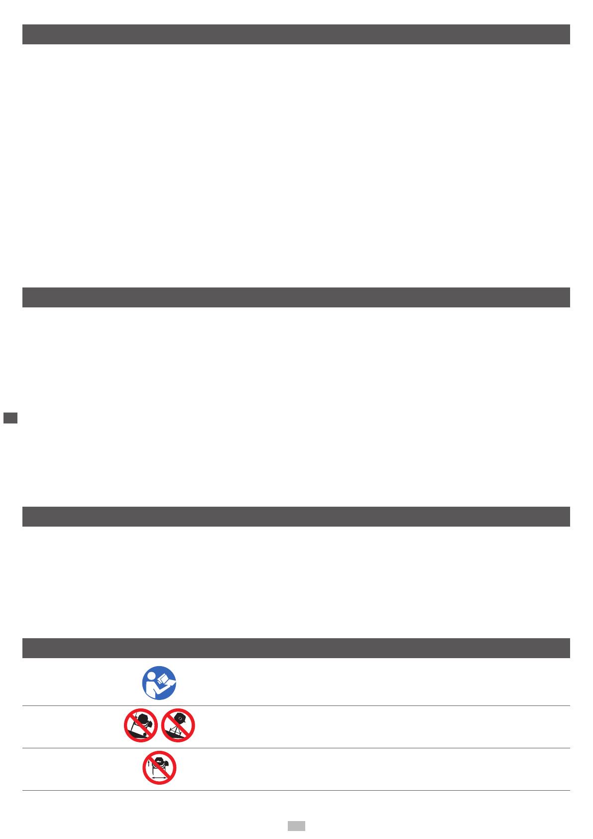
Symboles m
Lire la notice d‘utilisation avant la mise en service !
Placer la bétonneuse horizontalement sur un sol plan et
solide !
La bétonnière ne doit pas être déplacée en cours de
fonctionnement !
F
19
Ne pas laisser les personnes non autorisées et les enfants
s‘approcher de la machine !
Lappareil est doté d‘une isolation de protection !
Attention !
La classe de protection ne reste acquise que si des matéri-
aux isolants originaux sont utilisés en cas d‘intervention et si
les distances d‘isolation ne sont pas modiées.
Débrancher la che avant le nettoyage ou la maintenance !
Size: 20 (mm) 40 (mm)
Ø 25 mm
129 x 70
Le tambour mélangeur ne doit être opéré qu‘avec des équi-
pements de protection complètement fermés !
Porter des vêtements de protection !
Ne pas toucher le tambour en mouvement
Attention !
Risque d’écrasement au niveau du pignon/de la roue
crantée
Aide au montage !
Voir : Montage, Monter le tambour supérieur (Fig.6)
Utilisation conforme m
La machine correspond à la directive CE sur
les machines en vigueur.
La bétonneuse n‘est conçue que pour un
usage privé dans une maison ou un jardin.
Elle doit être utilisée dans le cadre des
caractéristiques techniques.
La bétonneuse est exclusivement conçue
pour fabriquer du béton et du mortier.
Les instructions de prévention des acci-
dents conceres et autres règles tech-
niques de sécurité généralement admises
doivent être observées.
La machine ne doit être utilisée, entrete-
nue ou réparée que par des personnes
la connaissant et infores des dangers.
Toute modication arbitraire de la machine
annule toute garantie du fabricant pour les
dommages en résultant.
La machine ne doit être utilisée qu‘avec des
accessoires originaux et des outils origin-
aux du fabricant.
Toute utilisation hors de ce cadre est con-
sidérée comme non conforme. Le fabricant
n‘est pas responsable des dommages
en résultant, seul l‘utilisateur en porte le
risque.
Attention ! Sont interdits :
Le fonctionnement dans des atmosphères
explosibles
Lutilisation dans le secteur alimentaire
Le mélange de substances explosives,
inammables et nocives.
Risques résiduels m
La machine est construite à la pointe de la
technique et selon les règles techniques de
sécurité reconnues. Toutefois, des risques
siduels peuvent survenir lors des travaux.
Risque de blessures dû aux pièces rotati-
ves
Danger dû au courant en cas d‘utilisation
de ligne de raccordement électrique non
conformes
En outre, et ce malgré toutes les mesures
préventives prises, des risques résiduels
cachés peuvent demeurer.
Les risques résiduels peuvent être minimi-
sés en observant les consignes de sécu-
rité, l‘une utilisation conforme et la notice
d‘utilisation.
Raccordement électrique m
Le moteur électrique installé est prêt à fonc-
tionner une fois raccordé. Le raccordement
correspond au dispositions de la VDE et DIN en
vigueur.
Le branchement au secteur effectué par le client
ainsi que la rallonge électrique utilisée doivent
correspondre à ces prescriptions.
Consignes importantes
En cas de surcharge du moteur, ce dernier
s‘arrête de lui-même.
Après un temps de refroidissement (d‘une durée
variable), le moteur peut être remis en marche.
Lignes de raccordement électriques défec-
tueuses
Des détériorations de l‘isolation sont souvent
présentes sur les lignes de raccordement élec-
triques
Les causes peuvent en être :
Des points de pression, si les lignes de
raccordement passent par des fenêtres ou
interstices de portes.
Des pliures dues à une xation ou à un
cheminement incorrects des lignes de
raccordement.
Des points d‘intersection si les lignes de
raccordement se croisent.
Des détériorations de l‘isolation dues à un
arrachement hors de la prise murale.
Des ssures dues au vieillissement de
l‘isolation. Des lignes de raccordement
électriques endommagées de la sorte ne
doivent pas être utilisées et, en raison de
F
20
leur isolation défectueuse, sont mortelle-
ment dangereuses !
Vérier régulièrement que les lignes de raccor-
dement électriques ne sont pas endommagées.
Assurez-vous que la ligne de raccordement ne
soit pas raccordée au réseau lors de la véri-
cation. Les lignes de raccordement électriques
doivent correspondre aux dispositions VDE et
DIN en vigueur. N‘utilisez que des lignes de
raccordement dotées du signe F 07 RN.
Lindication de la désignation du type sur la ligne
de raccordement est obligatoire.
Moteur à courant alternatif
Moteur à courant alternatif 230 V/ 50 Hz, tension
réseau 230 volt / 50 Hz.
L‘utilisation d‘un dispositif de protection contre
le courant de fuite (« FI ») est recommandé pour
un raccordement de 230 V. Si vous utilisez une
rallonge électrique, branchez-la directement
dans le FI.
Pour une utilisation en Suisse, ne branchez la
bétonneuse que dans les prises protégées par
un disjoncteur de protection contre le courant
de fuite.
Le branchement au secteur et la rallonge élec-
trique peuvent comporter 3 ou 2 brins.
3 brins : P + N + SL. - (1/N/PE); 2 brins : P +
N – (1/N)
Les rallonges électriques doivent avoir une sec-
tion transversale d‘au moins 1,5 mm².
La ligne de raccordement, la che et la boîte de
raccordement doivent être protégés des écla-
boussures d‘eau.
Le branchement au secteur est sécurisé avec 16
A maximum.
Les raccordements et réparations sur
l‘équipement électrique ne doivent être ef-
fectués que par un électricien spécialisé.
Pour toute question, veuillez indiquer les
données suivantes.
Type de courant du moteur.
Données de la plaque signalétique de la
machine.
En cas de retour du moteur, toujours envo-
yer l‘unité d‘entraînement complète avec
l‘interrupteur.
Éléments compris dans la liste de colisage Fig.1
1. Pied de support avant
2. Carter du moteur
3. Châssis
4. Roue pivotante
5. Partie supérieure du tambour
6. Fixation du support
7. Partie inférieure du tambour
8. Notice
9. Mécanisme mélangeur
10. Sachet suppmentaire (contenu dans g. 2)
11. Pied de support arrière avec essieu
12. 2 roues
13. Disque d‘arrêt
Caractéristiques techniques
Moteur ........................................................................................................................230V / 50 Hz 0,55 kW
Capacité .................................................................................................................................................125 l
Classe de protection .......................................................................................................................... IP 45D
(IP=International Protection; 4= Protection contre le contact avec un l d=1mm + Protection contre la pénétration de corps étrangers d>/=1mm; 5= Protection contre les jets d‘eau de toutes directions; D= Protection contre le contact avec un l
d=1mm 100mm de long)
Dimensions ................................................................................................... 1200mm x 710mm x 1400mm
Poids .....................................................................................................................................................50 kg
Information sur le bruit
Les niveaux sonores de la machine en fonction-
nement sont les suivants:
L
pA
: 7,2dB(A) K=3dB(A)
L
wA
: 93dB(A) K=3dB(A)
Vibration: 4.51m/s
2
K=1.5m/s
2
Avertissement : le bruit peut nuire gravement
à votre santé. Veuillez porter une protection
auditive si le bruit du moteur dépasse 85 dB
(A). Si le branchement électrique est défaillant,
le courant peut diminuer lors du démarrage de
la machine. Cela peut endommager d’autres
machines (par ex. des lampes clignotantes). Si la
puissance électrique correspond à Zmax < 0, 27,
une telle interférence ne devrait pas se produire
(si elle se produit, informez-en votre revendeur).
La valeur des émissions vibratoires donnée
ci-dessous a été mesurée grâce à un test
standardisé, et elle peut être utilisée pour
comparer une machine à usiner par rapport à
une autre ;
La valeur des émissions vibratoires donnée ci-
dessous peut également être utilisée pour une
première estimation de l’exposition.
Avertissement:
La valeur des émissions vibratoires peut dif-
férer lors de l’utilisation réelle de la machine
à usiner par rapport à la valeur spéciée, en
fonction de la manière dont la machine à usi-
ner est utilisée ;
Essayez de limiter au minimum l’exposition
aux vibrations. Pour réduire les niveaux de vi-
bration, vous pouvez par exemple porter des
gants lors de l’utilisation de la machine et li-
miter les heures de travail. Ce faisant, toutes
les parties du cycle de fonctionnement doivent
être prises en compte (par exemple, les pé-
riodes pendant lesquels la machine à usiner
est éteinte ou allumée sans charge).
Déballage
Sortir à deux la bétonneuse du carton.
Vériez l‘intégralité du contenu.
Informez le vendeur de toute irrégularité.
Montage
Attention !
La bétonneuse ne doit être utilisée qu‘après
avoir été montée complètement.
1. Monter les roues g. 3
Sur le pied de support arrière avec l‘essieu (11),
monter des deux côtés la goupille, la rondelle, la
roue (12), la rondelle, la goupille.
Courber légèrement la goupille après le mon-
tage
2. Monter le pied de support avant avec le
châssis g. 4
Monter le pied de support avant (1) avec 2 vis
M8x70, 2 rondelles de 8 mm, 2 bagues élas-
tiques, 2 écrous M8 sur le châssis (3) et serrez
fermement.
3. Monter le cssis avec le montant de roue
g. 5
Monter le cssis et le montant de roue cpl.
avec 2 vis à tête hexagonale M8x70, 2 rondelles
8 mm, 2 bagues élastiques, 2 écrous M8. Serrer
fermement les vis
4. Monter la partie inrieure du tambour
avec le châssis g. 6
Placer la partie inférieure du tambour (7) avec la
xation du tambour (6) sur le châssis prémonté,
serrer avec 2 vis à tête hexagonale M8x65, 2
  • Page 1 1
  • Page 2 2
  • Page 3 3
  • Page 4 4
  • Page 5 5
  • Page 6 6
  • Page 7 7
  • Page 8 8
  • Page 9 9
  • Page 10 10
  • Page 11 11
  • Page 12 12
  • Page 13 13
  • Page 14 14
  • Page 15 15
  • Page 16 16
  • Page 17 17
  • Page 18 18
  • Page 19 19
  • Page 20 20
  • Page 21 21
  • Page 22 22
  • Page 23 23
  • Page 24 24
  • Page 25 25
  • Page 26 26
  • Page 27 27
  • Page 28 28
  • Page 29 29
  • Page 30 30
  • Page 31 31
  • Page 32 32
  • Page 33 33
  • Page 34 34
  • Page 35 35
  • Page 36 36
  • Page 37 37
  • Page 38 38
  • Page 39 39
  • Page 40 40
  • Page 41 41
  • Page 42 42

Scheppach MIX125 Manuel utilisateur

Taper
Manuel utilisateur