Hitachi CM625ET Manuel utilisateur
- Catégorie
- Surveille CRT
- Taper
- Manuel utilisateur

USERS GUIDE
CM625ET

1
Table of Content
s
INTRODUCTION.............................................................2
Features
Package Overview
CAUTIONS.................................................................... 3
FCC Statement Warning .................................................5
TCO'99 Statement..........................................................6
For the Customers in the UK...........................................8
INSTALLATION..............................................................10
USER CONTROLS........................................................11
OSD FUNCTION DESCRIPTION.................................12
OSD ICON SUMMARY ................................................16
SPECIFICATIONS .........................................................18
TROUBLESHOOTING ...................................................19
Mon
i
tor

2
INTRODUCTION
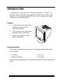
Congratulations on your purchase of this high performance 17" monitor. Us-
ing state-of-the-art electronics, this monitor can support up to 1600 x 1200
resolution. The on-screen display(OSD) allows you to customize the display
setting to suit your individual needs.
Features
J 17-inch monitor with a large, 325 x
243 mm viewable screen for
comfortable viewing.
J OSD controls for easy and accurate
adjustment of the screen image.
J Energy Star compliant to reduce
power consumption.
Package Overview
Please make sure the following items are in the shipping packing and found in
good condition:
* 17" Monitor * Power cord
* Tilt and swivel stand * This manual
Please save this packing material in case the monitor needs warranty service in the
future.

3
CAUTIONS
NEVER REMOVE THE REAR COVER !
The rear cover MUST be removed only by authorized service personnel. This colour monitor
contains high voltage components.
THE RECEPTACLE SHOULD BE CLOSE TO THE MONITOR AND EASILY ACCESSIBLE !
INSTALL THE UNIT IN AN SUITABLE ENVIRONMENT !
DO NOT expose this monitor to rain or moisture to prevent electric shock or fire hazard. This unit
is designed to be used in an office or business environment.
DO NOT subject the unit to vibrations, dust, or corrosive gases.
KEEP IN A WELL VENTILATED PLACE !
DO NOT cover this monitor or place anything against any sides (not only the top, right and left
side but also the rear and bottom side) of unit. Ventilation holes are provided at all sides of the
rear cover to prevent the temperature from rising.
KEEP AWAY FROM HEAT SOURCES !
AVOID placing the unit in direct sunshine or near a heating appliance.
BE CAREFUL OF MAGNETIC FIELDS !
DO NOT place a magnet, loudspeaker system, floppy disk drive, printer, or anything which will
generate magnetism near the unit. A magnetic field may cause blurred colours or distortion of the
displayed pattern.
BE CAREFUL OF GENERATED MAGNETISM !
After the power has been turned on or “DEGAUSS” button has been pressed, the CRT is
demagnetised for approximately 10 seconds. This generates a strong magnetic field around the
front cover which may affect the data stored on magnetic tape or disks near the front cover. Place
such magnetic recording equipment and tapes/disks away from this unit.
AMBIENT ILLUMINATION
Avoid direct rays of the sun or room lighting onto the CRT screen in order to prevent eye fatigue.
THE ENCLOSED POWER CORD MUST BE USED !
In Europe, a proper European standard approved power cord is to be used with this monitor. For
a rated current up to 6 A, a type not lighter than H05VV-F 3G 0.75 mm
2
or H05VVH2-F 3G 0.75
mm
2
must be used.
In USA/Canada, use a UL LISTED/CSA LABELLED or CERTIFIED power cord set meeting the
following specifications
Rating: min. 125V, 7A
Length: max. 3.0m
Type: SVT or SJT
Plug type: NEMA 5-15P figure, Parallel blade, Grounding type
Failure to do so may cause fire or electric shock hazard.
USE ONLY THE CORRECT VOLTAGE POWER OUTLET WITH SAFETY GROUND
CONNECTION !
100 - 120 V for USA, Canada, etc.
200 - 240 V for Europe, etc.
(This monitor will automatically adjust to the input voltage 100 - 120 / 200 - 240V.)
CAUTION for 200 - 240V operation only

4
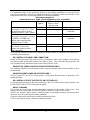
This equipment relies on the protective devices in the building installation for short-circuit and
over-current protection. Refer to the following table for the suitable number and location of the
protective devices which should be provided in the building installation.
Informative examples of
protective devices in single - phase equipment or sub - assemblies
Protection
against
Minimum number of
fuses or circuit -
breaker poles
Location
Case A: Equipment to be
connected to POWER SYSTEMS
wi
th earthed neutral reliably
identified, except for Case C below.
Earth faults
Overcurrent
1
1
Phase conductor
Either of the two
conductors
Case B: Equipment to be
connected to any supply, including
IT POWER SYSTEMS and
supplies with reversible plugs,
except for Case C below.
Earth faults
Overcurrent
2
1
Both conductors
Either of the two
conductors
Case C: Equipment to be
connected to 3-wire power
systems with earthed neutral
reliably identified.
Earth faults
Overcurrent
2
2
Each phase conductor
Each phase conductor
Verify that the protective devices in the building installation meets the conditions in the table prior
to installing the equipment.
BE CAREFUL OF POWER CORD CONNECTION !
Before inserting the plug of the power cord into a receptacle of the correct voltage, check that the
connection portion of the power cord is clean (with no dust). Then, insert the plug of power cord
to a receptacle firmly, otherwise it may cause electrical shock or fire.
REMOVE THE POWER CORD FOR COMPLETE SEPARATION !
For complete separation from the power source, remove the power cord from the monitor or from
the wall outlet.
AVOID FREQUENT POWER ON-OFF SWITCHING !
DO NOT repeat OFF and ON in a short period. It may cause blurred colours or distortion of the
displayed pattern.
BE CAREFUL OF STATIC ELECTRICITY ON CRT SURFACE !
To prevent electrical shock by the static electricity on the CRT surface, disconnect the power cord
at least 30 SECONDS AFTER turning off the power.
ABOUT CLEANING
This monitor has a non-glare and anti-electrostatic treatment on the surface of the screen. Use
water or alcoholic solvent with soft cloth like gauze to clean the surface of the screen.
NEVER use abrasive, glass cleaner containing highly concentrated ammonia and strong base
chemicals since they damage the surface treatment.
Clean the cabinet and controls with a lightly moistened soft cloth.
DO NOT use aerosol sprays, solvents or abrasive cleaners.

5
CAUTIONS (Continued)
FCC Statement Warning
WARNING : This equipment has been tested and found to comply with the limits for a Class B
digital device, pursuant to Part 15 of the FCC Rules. These limits are designed to provide
reasonable protection against harmful interference in a residential installation. This equipment
generates, uses, and can radiate radio frequency energy and, if not installed and used in
accordance with the instructions, may cause harmful interference to radio communications.
However, there is no guarantee that interference will not occur in a particular installation. If this
equipment does cause harmful interference to radio or television reception, which can be
determined by turning the equipment off and on, the user is encouraged to try to correct the
interference by one or more of the following measures:
- Reorient or relocate the receiving antenna.
- Increase the separation between the equipment and receiver.
- Connect the equipment into an outlet on a circuit different from that to which the receiver is
connected.
- Consult the dealer or an experienced radio / TV technician for help.
INSTRUCTIONS TO USERS : This equipment complies with the requirements of FCC (Federal
Communication Commission) equipments provided that following conditions are met.
(1) Power cord: Unshielded power cord must be used.
(2) Do not exceed the specified level.
CAUTION : Changes or modifications not expressly approved by the party responsible for
compliance could void the user’s authority to operate the equipment.
Declaration of Conformity
According to 47CFR, Part 2 and 15 for
Class B Personal Computers and
Peripherals; and / or
CPU Boards and Power Supplies used
With Class B Personal Computers:
We: HITACHI America, Ltd.
Located at: 2000 Sierra Point Parkway, Brisbane, CA 94005-1835 U.S.A.
Declare under sole responsibility that the product identified herein, complies with 47CFR Part 2 and 15 of the FCC
rules as a Class B digital device. Each product marketed, is identical to the representative unit tested and found
to be compliant with the standards.. Records maintained continue to reflect the equipment being produced can be
expected to be within the variation accepted, due to quantity production and testing on a statistical basis as
required by 47FCR § 2.909. Operation is subject to the following two conditions: (1) This device may not cause
harmful interference, and (2) This device must accept any interference received, including interference that may
cause undesired operation. The above named party is responsible for ensuring that the equipment complies with
the standards of 47CFR §§ 15.101 to 15.109.
Trade name: Colour Monitor
Model Number: CM625
Signature of Party Responsible:
Printed name of Party Responsible: Hideaki Kusaba
Executed on (Date), at (Place): April 10, 2000, CA, U.S.A.
For the Customers in CANADA
NOTICE : This Class B digital apparatus complies with Canadian ICES-003.

6
TCO'99 Statement
Congratulations!
You have just purchased a TCO'99 approved and labelled product! Your choice has provided you with a
product developed for professional use. Your purchase has also contributed to reducing the burden on the
environment and also to the further development of environmentally adapted electronics products.
This product meets the requirements for the TCO'99 scheme which provides for an international environ-
mental and quality labelling of personal computers. The labelling scheme was developed as a joint effort by
the TCO (The Swedish Confederation of Professional Employees), Svenska Naturskyddsforeningen (The
Swedish Society for Nature Conservation), Statens Energimyndighet (The Swedish National Energy
Administration) and SEMKO AB.
The requirements cover a wide range of issues: environment, ergonomics, usability, reduction of electric
and magnetic fields, energy consumption and electrical safety.
Why do we have environmentally labelled computers?
In many countries, environmental labelling has become an established method for encouraging the
adaptation for goods and services to the environment. The main problem, as far as computers and other
electronics equipment are concerned, is that environmentally harmful substances are used both in the
products and during their manufacture. Since it is not so far possible to satisfactorily recycle the majority of
electronics equipment, most of these potentially damaging substances sooner or later enter nature.
There are also other characteristics of a computer, such as energy consumption levels, that are important
from the viewpoints of both the work (internal) and natural (external) environments. Since all methods of
electricity generation have a negative effect on the environment (e.g. acidic and climate-influencing
emissions, radioactive waste). It is vital to save energy. Electronics equipment in offices is often left running
continuously and thereby a lot of energy.
What does the environmental labelling involve?
The environmental demands has been developed by Svenska Naturskyddsforeningen (The Swedish Society
for Nature Conservation). These demands impose restrictions on the presence and use of heavy metals,
brominated and chlorinated flame retardants, CFCs (freons) and chlorinated solvents, among other things.
The product must be prepared for recycling and the manufacturer is obliged to have an environmental policy
which must be adhered to in each country where the company implements its operational policy.
The energy requirements include a demand that the computer and/or display, after a certain period of
inactivity, shall reduce its power consumption to a lower level in one or more stages. The length of time to
reactivate the computer shall be reasonable for the user.

7
Below you will find a brief summary of the environmental requirements met by this product. The complete
environmental criteria document may be ordered from:
TCO Development
SE-114 94 Stockholm, Sweden
Fax: +46 8 782 92 07
Email (Internet) : [email protected]
Current information regarding TCO'99 approved and labelled products may also be obtained via the Internet, using
the address: http://www.tco-info.com/
Environmental requirements
Flame retardants
Flame retardants are present in printed circuit boards, cables, wires, casings and housings. Their purpose is to
prevent, or at least to delay the spread of fire. Up to 30% of the plastic in a computer casing can consist of flame
retardant substances. Most flame retardants contain bromine or chloride, and those flame retardants are chemically
related to another group of environmental toxins, PCBs. Both the flame retardants containing bromine or chloride
and the PCBs are suspected of giving rise to severe health effects, including reproductive damage in fish-eating
birds and mammals, due to the bio-accumulative* processes. Flame retardants have been found in human blood
and researchers fear that disturbances in foetus development may occur.
The relevant TCO'99 demand requires that plastic components weighing more than 25 grams must not contain
flame retardants with organically bound bromine or chlorine. Flame retardants are allowed in the printed circuit
boards since no substitutes are available.
Cadmium
Cadmium is present in rechargeable batteries and in the colour-generating layers of certain computer displays.
Cadmium damages the nervous system and is toxic in high doses. The relevant TCO'99 requirement states that
batteries, the colour-generating layers of display screens and the electrical or electronics components must not
contain any cadmium.
Mercury
Mercury is sometimes found in batteries, relays and switches. It damages the nervous system and is toxic in high
doses. The relevant TCO'99 requirement states that batteries may not contain and mercury. It also demands that
mercury is not present in any of the electrical or electronics components associated with the labelled unit. There is
however one exception. Mercury is, for the time being, permitted in the back light system of flat panel monitors as
there today is no commercially available alternative. TCO aims on removing this exception when a mercury free
alternative is available.
CFCs (freons)
The relevant TCO'99 requirement states that neither CFCs nor HCFCs may be used during the manufacture and
assembly of the product. CFCs (freons) are sometimes used for washing printed circuit boards. CFCs break down
ozone and thereby damage the ozone layer in the stratosphere, causing increased reception on earth of ultraviolet
light with e.g. increased risks of skin cancer (malignant melanoma) as a consequence.
Lead
Lead can be found in picture tubes, display screens, solders and capacitors. Lead damages the nervous system and
in higher doses, causes lead poisoning. The relevant TCO'99 requirement permits the inclusion of lead since no
replacement has yet been developed.
*Bio-accumulative is defined as substances which accumulate within living organisms
**Lead, Cadmium and Mercury are heavy metals which are BIO-accumulative

8
CAUTIONS (Continued)
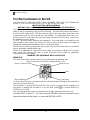
For the Customers in the UK
THIS PRODUCT IS SUPPLIED WITH A TWO PIN MAINS PLUG FOR USE IN MAINLAND
EUROPE. FOR THE UK PLEASE REFER TO THE NOTES ON THIS PAGE.
IMPORTANT FOR UNITED KINGDOM
WORDING FOR CLASS ? EQUIPMENT INSTRUCTION BOOKS AND LABELS
The mains lead on this equipment is supplied with a moulded plug incorporating a fuse, the
value of which is indicated on the pin face of the plug. Should the fuse need to be replaced,
an ASTA or BSI approved BS 1362 fuse must be used of the same rating. If the fuse cover
is detachable never use the plug with the cover omitted. If a replacement fuse cover is re-
quired, ensure it is of the same colour as that visible on the pin face of the plug. Fuse covers
are available from your dealer.
DO NOT cut off the mains plug from this equipment. If the plug fitted is not suitable for the
power outlets in your home or the cable is too short to reach a power outlet, then obtain an
appropriate safety approved extension lead or consult your dealer.
Should it be necessary to change the mains plugs, this must be carried out by a competent
person, preferably a qualified electrician.
If there is no alternative to cutting off the mains plug, ensure that you dispose of it immedi-
ately, having first removed the fuse, to avoid a possible shock hazard by inadvertent
connection to the mains supply.
WARNING: THIS EQUIPMENT MUST BE EARTHED
IMPORTANT
The wires in the mains lead are coloured in accordance with the following code:
Green and Yellow = Earth, Blue = Neutral, Brown = Live.
Green & Yellow to Earth Brown to Live
Fuse
Blue to Neutral Cord Clamp
As these colours may not correspond with the coloured markings identifying the terminals in
your plug, proceed as follows:
The wire which is coloured GREEN and YELLOW must be connected to the terminal in the
plug which is marked with the letter E or by the earth symbol or coloured GREEN or
GREEN and YELLOW.
The wire coloured BLUE must be connected to the terminal marked with the letter N or
coloured BLUE or BLACK. The wire coloured BROWN must be connected to the
terminal marked with the letter L or coloured BROWN or RED.

9
NOTE:
The information in this manual is subject to change without notice. The manufacturer assumes no
responsibility for any errors that may appear in this manual.
TRADEMARK ACKNOWLEDGEMENT
VGA is a registered trademark of International Business Machines Corporation.
VESA is a trademark of a non-profit organization, Video Electronics Standard Association.
ENERGY STAR
®
is a U.S. registered mark of Environmental Protection Agency (EPA).
REMARQUE:
Les informations contenues dans ce manuel peuvent être modifiées sans préavis. Le constructeur
n’accepte aucune responsabilité pour les erreurs qui peuvent éventuellement apparaître dans ce
manuel.
MARQUES DÉPOSÉES
VGA est une marque déposée d’ International Business Machines Corporation.
VESA est la marque d’une organisation sans but lucratif, la Video Electronics Standard Association.
ENERGY STAR
®
est une marque de l’ EPA (Environmental Protection Agency, USA).
HINWEIS:
Änderungen der Daten in dieser Bedienungsanleitung sind vorbehalten. Der Hersteller übernimmt
keine Haftung für jegliche in diesem Handbuch eventuell enthaltenen lrrtümer.
GESCHÜTZTE WARENZEICHEN
VGA ist ein eingetragenes Warenzeichen der International Business Machines Corporation.
VESA ist ein Warenzeichen der Video Electronics Standard Association, einer Organisation ohne
Erwerbscharakter.
ENERGY STAR
®
ist ein Warenzeichen der Environmental Protection Agency (EPA).
NOTA:
La información contenida en este manual está sujeta a cambios sin previo aviso. El fabricante no se
responsabiliza de los errores que puedan aparecer en este manual.
RECONOCIMIENTO DE MARCAS
VGA es una marca registrada de International Business Machines Corporation.
VESA es una marca registrada de una organización sin ánimo de lucro, Video Electronics Standard
Association.
ENERGY STAR
®
es una marca de Environmental Protection Agency (EPA).
NOTA:
Tutte le informazioni di questo manuale sono soggette ad essere modificate senza preavviso. Il
costruttore non si assume responsabilita’ per errori che possono essere riportati sul manuale.
Marchi di fabbrica riconosciuti.
VGA e’ um marchio di fabbrica regisrato da International Business Machine Corporation.
VESA e’ il marchio di riconoscimento della organizzazione a non-profitto, Video Electronics Standard
Association.
ENERGY STAR
®
e’ il marchio di fabbrica della Eviromental Protection Agency (EPA).

10
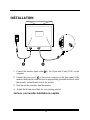
INSTALLATION
12
1. Connect the monitor signal cable to the 15-pin mini D-sub (VGA) on the
computer.
2. Connect the power cord to the power connector on the back panel of the
monitor, then plug the other end into an appropriately grounded electrical outlet
that is easily accessible and close to the monitor.
3. First turn on the computer, then the monitor.
4. Adjust the tilt and swivel base for your viewing comfort.
And now, your monitor installation is complete.
1

11
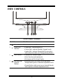
USER CONTROLS
Front Panel Controls
Control Function
1
Power Button Turn monitor on and off.
2
Power LED
Indicator
• Green light - indicates power on
• Yellow light - indicates Standby/ Suspend mode
• Amber light - indicates Sleep mode For more infor-
mation on power states, see "Energy Saving Modes."
3
Select Button
• Launches On -Screen Display
• Select functions and adjustments
• Exit menus and On-Screen Display
4
Backward and
Forward
Buttons
• Backward button (left arrow) moves backward
through menu options or decreases adjustment levels.
• Forward button (right arrow) moves forward through
menu options or increases adjustment levels.

12
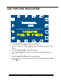
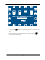
OSD FUNCTION DESCRIPTION
1. Press the select button to display the OSD Menu.
2. To select function, press and button until the function you want is high-
lighted.
3. Press the select button to choose the function
4. Use the and button to increase or decrease the adjustment of this func-
tion.
5. Press the select button to save the new adjustment.
6. Select the Exit icon if you want to exit the OSD function then press the select
button once.

13
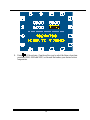
7. If you select the function, the second page function is available just like
above.
Repeat step2~step5 to adjust the function you want, then select the
icon to go back to the first page.

14
8. Enter ( Colour temp. ) function allow you to select the three colour tem-
peratures (9300, 6500 and 5000 ) or the user that makes your desired colour
temperature.

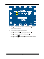
15
(a) Press to select 9300, 6500, 5000 or USER then press . It will
be save and exit this function.
(b) If select USER, R,G,B gain function available.
Press select R,G,B, ( Reset Default),then press .
Press to adjust the gain ( R,G or B ),then press .
Press to select , then press to save and exit this function.

16
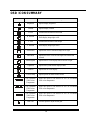
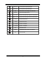
OSD ICON SUMMARY
Icon Function Function Description
Brightness Adjusts display brightness
Contrast Adjusts display contrast
H. Size Increases and decreases screen width
H. Position
Shifts display image right or left
V. Size Increases and decrease screen height
V. Position Shifts display image up or down
Pin Balance Adjusts the curve of the entire image left or right
Pincushion Adjusts the curve of the left and right sides inward and
outward
Parallelogram Adjusts the tilt of the display sides to the left or right
Trapezoid Adjusts the top and bottom display widths
Rotation Adjusts the tilt of the display
Colour Temp Adjusts picture to make vibrant colours
CIE coordinate
9300 Colour
Temperature
Select this option to set monitor for the CIE coordinate
9300 colour temperature.
CIE coordinate
6500 Colour
Temperature
Select this option to set monitor for the CIE coordinate
6500 colour temperature.
CIE coordinate
5000 Colour
Temperature
Select this option to set monitor for the CIE co
ordinate
5000 colour temperature.
Red Gain Use this option to adjust the red gain.

17
Green Gain Use this option to adjust the green gain.
Blue Gain Use this option to adjust the blue gain.
Reset Reset the three colour settings to the default value.
Advanced Enter the second page function
Top Corner Adjusts screen upper-right & upper-left corner distortion
Bottom Corner Adjusts screen lower-right & lower-left corner distortion
H. Moire Adjusts horizontal moire.
V. Moire Adjusts vertical moire.
H. Convergence Adjusts H convergence
V. Convergence Adjusts V convergence
Reset
Reset default values
Degauss Demagnetises screen to reduce colour impurities
Exit Close OSD menu

18
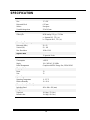
SPECIFICATION
Screen
Size 17" CRT
Horizontal Pitch 0.25 mm
Surface Non-glare
Viewable Image Area 325x 243 mm
Input Signal
Video Sync. RGB Analog 0.7Vp-p / 75 Ohm
a. Separate H/V, TTL (+/-)
b. Composite H+V, TTL (+/-)
Scanning Frequency
Horizontal (KHz) 30 - 95
Vertical (Hz) 50 - 160
Max. Resolution 1600 x 1200
Signal Cable
15-pin mini D-sub
Power
Consumption <105 W
Supply 100 - 240VAC, 50 /60Hz
Power Management Complies with EPA Energy Star, VESA DPMS
Display Modes
Preset 13
User 15
Operating
Operating Temperature
0 - 35 °C
Relative Humidity 10 - 90 %
Dimensions (L x W x H)
Including Stand 442 x 404 x 431 (mm)
Weight
Unpacked 16.8 kgs ( 37.0 lbs )
Packed in box 19.8 kgs ( 43.6 lbs )

19
TROUBLESHOOTING
Please make reference to following solutions for most of the failure symptoms
occurred. If the symptom remains after trying the suggested solutions, please con-
tact your local authorized service centre.
Problem: Power LED is not lit when monitor is powered on.
@ Check to make sure that the power cord is properly connected.
@ Make sure that extension cord or the surge protector is turned on if the
monitor is plugged into such equipment.
Problem: No display appears on screen.
@ Make sure that the computer is turned on.
@ Make sure that the signal cable is properly connected to the video adapter
port on the PC.
Problem: Display image is either flickering or unstable.
@ Make sure that the signal cable is properly connected to the video adapter
port on the PC.
Problem: Image is bouncing or in a wave pattern.
@ Move any electrical devices interference. (Please refer to the FCC state-
ment at the beginning of the manual for more details of display
interference).
Problem: There are two slim horizontal lines on the screen of the
monitor.
@ That is one of Monitor's characters. It is not out of work.
La page est en cours de chargement...
-
 1
1
-
 2
2
-
 3
3
-
 4
4
-
 5
5
-
 6
6
-
 7
7
-
 8
8
-
 9
9
-
 10
10
-
 11
11
-
 12
12
-
 13
13
-
 14
14
-
 15
15
-
 16
16
-
 17
17
-
 18
18
-
 19
19
-
 20
20
-
 21
21


Hitachi CM625ET Manuel utilisateur
- Catégorie
- Surveille CRT
- Taper
- Manuel utilisateur
dans d''autres langues
- English: Hitachi CM625ET User manual
Documents connexes
-
Hitachi CM615ET Manuel utilisateur
-
-
-
-
-
-
Hitachi CP-A302WN Manuel utilisateur
-
-
Hitachi CPD32WN Mode d'emploi
-
Hitachi iPJAW250N Mode d'emploi
