
CAUTION – RISK OF SHOCK – Disconnect Power at the main
circuit breaker panel or main fuse box before starting and during
the installation.
1) Thread hexnut onto the threaded pipe about 1/4”.
2) Screw the same end of threaded pipe into hole in center of
mounting strap so a few threads are exposed on the
extruded side of mounting strap. Tighten the hexnut.
3) Connect the mounting stap to the outlet box with the strap
mounting screws.
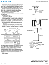
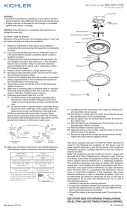
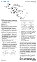
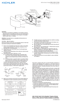
4) Grounding instructions: (See Illus. A or B).
A) On fixtures where mounting strap is provided with a hole
and two raise dimples. Wrap ground wire from outlet
box around green ground screw, and thread into hole.
B) On fixtures where a cupped washer is provided. Attach
ground wire from outlet box under cupped washer and
green ground screw, and thread into mounting strap.
If fixture is provided with ground wire. Connect fixture
ground wire to outlet box ground wire with wire connector.
(Not provided.) After following the above steps. Never connect
ground wire to black or white power supply wires.
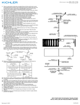
5) Make wire connections (connectors not provided.) Reference
chart below for correct connections and wire accordingly.
GREEN GROUND
SCREW
CUPPED
WASHER
OUTLET BOX
GROUND
FIXTURE
GROUND
DIMPLES
WIRE CONNECTOR
OUTLET BOX
GROUND
GREEN GROUND
SCREW
FIXTURE
GROUND
A
B
Connect Black or
Red Supply Wire to:
Connect
White Supply Wire to:
Black White
*Parallel cord (round & smooth) *Parallel cord (square & ridged)
Clear, Brown, Gold or Black
without tracer
Clear, Brown, Gold or Black
with tracer
Insulated wire (other than green)
with copper conductor
Insulated wire (other than green)
with silver conductor
*Note: When parallel wires (SPT I & SPT II)
are used. The neutral wire is square shaped
or ridged and the other wire will be round in
shape or smooth (see illus.)
Neutral Wire
Date Issued: 1/13/17 IS-10795LED-US
We’re here to help 866-558-5706
Hrs: M-F 9am to 5pm EST
SEE OTHER SIDE FOR SPANISH TRANSLATIONS.
VEA EL OTRO LADO DE TRADUCCIONES AL ESPAÑOL.
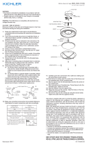
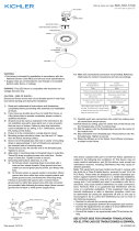
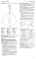
6) Carefully push wire connections back into outlet box making
sure all connections remain secure.
7) Push fixture to wall, carefully passing mounting screws
through holes in fixture.
8) Slip the spacer onto the threaded pipe and into the center of
the module hole.
9) Slip lockwasher over threaded pipe. Thread hexnut onto the
threaded pipe. Tighten to secure.
10) Raise a diffuser bracket arm (with the slot facing up) to the
bottom of the canopy. Align the two holes of the bracket arm
with the holes of the canopy.
11) Thread two lock-up knobs through the holes to secure the
lower diffuser bracket arm into place.
12) Lower the diffuser and rest the center edge into the slot of
the bracket arm.
13) While holding the diffuser in place: lower the second diffuser
bracket arm (with the slot facing down) to the top of the
canopy.
14) Slip the the slot of the upper bracket arm over the top edge
of the diffuser.
15) Align the two holes of the upper diffuser bracket arm with
the holes of the canopy.
16) Thread two lock-up knobs through the holes to secure the
upper diffuser bracket arm into place.
WIRE
CONNECTORS
OUTLET BOX
HEXNUT
THREADED PIPE
SPACER
HEXNUT
LED MODULE
COVER
CANOPY
DIFFUSER
DIFFUSER BRACKET ARM
DIFFUSER BRACKET ARM
LOCK-UP KNOBS
LOCK-UP KNOBS
STRAP MOUNTING SCREW(S)
MOUNTING STRAP

PRECAUCIÓN – RIESGO DE DESCARGA ELÉCTRICA – Desco-
necte la electricidad en el panel principal del interruptor automáti-
co o caja principal de fusibles antes de comenzar y durante la
instalación.
1) Enrosque la tuerca hexagonal sobre el tubo roscado
alrededor de 1/4 “.
2) Atornille el mismo extremo del tubo roscado en el orificio en
el centro de la correa de montaje, de modo que queden
expuestas unas cuantas roscas en el lado extruido de la
correa de montaje. Apriete la tuerca hexagonal.
3) Instrucciones de conexión a tierra solamente para los
Estados Unidos. (Vea la ilustracion A o B).
A) En las lámparas que tienen el fleje, de montaje con un
agujero y dos hoyuelos realzados. Enrollar el alambre a
tierra de la caja tomacorriente alrededor del tornillo
verde y pasarlo por el aquiero.
B) En las lámparas con una arandela acopada. Fijar el
alambre a tierra de la caja tomacorriente del ajo de la
arandela acoada y tornillo verde, y paser por el fleje de
montaje.
Si la lámpara viene con alambre a tierra. Conecter el
alambre a tierra de la lámpara al alambre a tierra de la caja
tomacorriente con un conector de alambres. (No incluido)
Espués de seguir los pasos anteriores. Nunca conectar el
alambra a tierra a los alambres eléctros negro o blanco.
4) Haga les conexiones de los alambres (no se proveen los
connectores.) La tabla de referencia de abajo indica las
conexiones correctas y los alambres correspondientes.
Date Issued: 1/13/17 IS-10795LED-US
Conectar el alambre de
suministro negro o rojo al
Conectar el alambre de
suministro blanco al
Negro Blanco
*Cordon paralelo (redondo y liso)
*Cordon paralelo (cuadrado y estriado)
Claro, marrón, amarillio o negro
sin hebra identificadora
Claro, marrón, amarillio o negro
con hebra identificadora
Alambre aislado (diferente del verde)
con conductor de cobre
Alambre aislado (diferente del
verde) con conductor de plata
*Nota: Cuando se utiliza alambre paralelo
(SPT I y SPT II). El alambre neutro es de forma
cuadrada o estriada y el otro alambre será de
forma redonda o lisa. (Vea la ilustracíón).
Hilo Neutral
ARANDELA
CONCAVA
TIERRA DE LA
CAJA DE SALIDA
TORNILLO DE TIERRA,
VERDE
DEPRESIONES
TIERRA
ARTEFACTO
CONECTOR DE ALAMBRE
TIERRA DE LA
CAJA DE SALIDA
TORNILLO DE TIERRA,
VERDE
TIERRA
ARTEFACTO
A
B
We’re here to help 866-558-5706
Hrs: M-F 9am to 5pm EST
SEE OTHER SIDE FOR ENGLISH TRANSLATIONS.
VEA EL OTRO LADO DE TRADUCCIONES AL INGLÉS.
5) Presione con cuidado las conexiones de los cables de nuevo
en la caja de salida asegurándose de que todas las conexio
nes permanezcan seguras. Empuje la unidad contra la pared,
pasando con cuidado al tubo roscado a travès del agujero.
6) Atornille las bolas roscadas en los tornillos de montaje. Ariete
las bolas roscadas para sujetar a través de agujeros en el ac
cesorio.
7) Empuje la fijación a la pared, pasando cuidadosamente los
tornillos de montaje a través de los agujeros en el accesorio.
8) Deslice el espaciador en el tubo roscado y en el centro del
agujero del módulo.
9) Deslice la arandela de seguridad sobre el tubo roscado.
Enrosque la tuerca hexagonal en el tubo roscado. Apriete
para asegurar.
10) Levante un brazo del soporte del difusor (con la ranura hacia
arriba) hacia la parte inferior del toldo. Alinee los dos orificios
del brazo del soporte con los orificios del dosel.
11) Enrosque dos botones de bloqueo a través de los orificios
para fijar el brazo inferior del soporte del difusor en su lugar.
12) Baje el difusor y coloque el borde central en la ranura del
brazo del soporte.
13) Mientras sostiene el difusor en su lugar: baje el brazo del
segundo soporte del difusor (con la ranura hacia abajo) hasta
la parte superior del toldo.
14) Deslice la ranura del brazo del soporte superior sobre el borde
superior del difusor.
15) Alinee los dos orificios del brazo del soporte difusor superior
con los orificios del dosel.
16) Enrosque dos botones de bloqueo a través de los orificios
para fijar el brazo superior del soporte del difusor en su lugar.
Conectores
de alambre
CAJA DE SALIDA
TUERCA HEXAGONAL
TUBO ROSCADO
SEPARADOR
TUERCA HEXAGONAL
CUBIERTA
DEL MÓDULO LED
ESCUDETE
DIFUSER
BRAZO DEL SOPORTE
BRAZO DEL SOPORTE
PERILLAS DE SUJECIÓN
PERILLAS DE SUJECIÓN
TORNILLOS DE MONTAJE
DE LA ABRAZADERA
ABRAZADERA DE MONTAJE

CAUTION – RISK OF SHOCK – Disconnect Power at the main
circuit breaker panel or main fuse box before starting and during
the installation.
1) Thread hexnut onto the threaded pipe about 1/4”.
2) Screw the same end of threaded pipe into hole in center of
mounting strap so a few threads are exposed on the ex
truded side of mounting strap. Tighten the hexnut.
3) Connect the mounting strap to the outlet box with the stap
mounting screws.
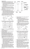
4) Make wire connections (connectors not provided.) Reference
chart below for correct connections and wire accordingly.
5) Carefully push wire connections back into outlet box making
sure all connections remain secure.
6) Push fixture to wall, pass the center hole of the fixture over
the threaded pipe on the mounting strap.
7) Slip the spacer onto the threaded pipe and into the center of
the module hole.
8) Slip lockwasher over threaded pipe. Thread hexnut onto the
threaded pipe. Tighten to secure.
9) Raise a diffuser bracket arm (with the slot facing up) to the
bottom of the canopy. Align the two holes of the bracket arm
with the holes of the canopy.
10) Thread two lock-up knobs through the holes to secure the
lower diffuser bracket arm into place.
11) Lower the diffuser and rest the center edge into the slot of
the bracket arm.
12) While holding the diffuser in place: lower the second diffuser
bracket arm (with the slot facing down) to the top of the
canopy.
13) Slip the the slot of the upper bracket arm over the top edge
of the diffuser.
14) Align the two holes of the upper diffuser bracket arm with
the holes of the canopy.
15) Thread two lock-up knobs through the holes to secure the
upper diffuser bracket arm into place.
Connect Black or
Red Supply Wire to:
Connect
White Supply Wire to:
Black White
*Parallel cord (round & smooth) *Parallel cord (square & ridged)
Clear, Brown, Gold or Black
without tracer
Clear, Brown, Gold or Black
with tracer
Insulated wire (other than green)
with copper conductor
Insulated wire (other than green)
with silver conductor
*Note: When parallel wires (SPT I & SPT II)
are used. The neutral wire is square shaped
or ridged and the other wire will be round in
shape or smooth (see illus.)
Neutral Wire
Date Issued: 1/13/17 IS-10795LED-CB
INSTRUCTIONS
For Assembling and Installing Fixtures in Canada
Pour L’assemblage et L’installation Au Canada
Connecter le fil noir ou
rouge de la boite
Connecter le fil blanc de la boîte
A Noir A Blanc
*Au cordon parallèle (rond et lisse)
*Au cordon parallele (à angles droits el strié)
Au bransparent, doré, marron, ou
noir sans fil distinctif
Au transparent, doré, marron, ou
noir avec un til distinctif
Fil isolé (sauf fil vert) avec
conducteur en cuivre
Fil isolé (sauf fil vert) avec
conducteur en argent
*Remarque: Avec emploi d’un fil paralléle
(SPT I et SPT II). Le fil neutre est á angles
droits ou strié et l’autre fil doit étre rond ou
lisse (Voir le schéma).
Fil Neutre
We’re here to help 866-558-5706
Hrs: M-F 9am to 5pm EST
ATTENTION – RISQUE DE DÉCHARGES ÉLECTRIQUES
Couper le courant au niveau du panneau du disjonc-
teur du circuit principal ou de la boîte à fusibles
principale avant de procéder à l’installation.
1) Enfiler l’écrou hexagonal sur le tuyau fileté d’environ 1/4 “.
2) Vissez la même extrémité de tuyau fileté dans le trou au
centre de La sangle de montage afin que quelques fils
soient exposés sur le côté extruded de la sangle de
montage. Serrer l’hexagone.
3) Raccordez la sangle de montage à la boîte de sortie avec
les vis de fixation stap.
4) Connecter les fils (connecteurs non fournis). Se reporter au
tableau ci-dessous pour faire les connexions.
5) Replacer soigneusement les connexions de fil dans la boîte
de sortie en s’assurant que toutes les connexions restent
sécurisées.
6) Plaquez le luminaire contre le mur, en passant soigneusement
les vis de montage dans le luminaire.
7) Glisser l’entretoise sur le tuyau fileté et dans le centre du
trou du module.
8) Glisser le lave vaisselle sur le tuyau fileté. Enfiler l ‘hexa-
gone sur le tuyau fileté. Serrer pour fixer.
9) Soulevez un bras de support de diffuseur (avec la fente vers
le haut) vers le bas de la verrière. Aligner les deux trous du
bras de support avec les trous de la verrière.
10) Enfiler deux boutons de blocage à travers les trous pour
fixer le bras inférieur du support du diffuseur en place.
11) Abaisser le diffuseur et reposer le bord central dans la fente
du bras de support.
12) Tout en tenant le diffuseur en place: abaissez le deuxième
diffuseur (Avec la fente orientée vers le bas) vers le haut de
la voilure.
13) Glissez la fente du bras de support supérieur sur le bord
supérieur du diffuseur.
14) Alignez les deux trous du bras de support du diffuseur
supérieur avec les trous du couvert.
15) Vissez deux boutons de blocage à travers les trous pour
fixer le bras supérieur du diffuseur en place.
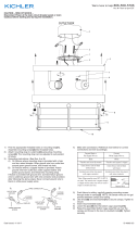
WIRE CONNECTORS
CONNECTEURS DE FIL
OUTLET BOX
BOÎTE À PRISES
HEXNUT
ÉCROU HEXAGONAL
THREADED PIPE
TUBE FILTÉ
SPACER /ENTRETOISE
HEXNUT
ÉCROU HEXAGONAL
LED MODULE COVER
COUVERCLE
DU MODULE LED
CANOPY
CAPUCHON
DIFFUSER
DIFFUSEUR
DIFFUSER BRACKET ARM
BRAS DE SUPPORT
DIFFUSER BRACKET ARM
BRAS DE SUPPORT
LOCK-UP KNOBS
BOULES DE BLOCAGE
LOCK-UP KNOBS
BOULES DE BLOCAGE
STRAP MOUNTING SCREW(S)
VIS DE L'ÉTRIER DE MONTAGE
MOUNTING STRAP
-
 1
1
-
 2
2
-
 3
3


dans d''autres langues
- English: Kichler 10795NILED User manual
- español: Kichler 10795NILED Manual de usuario
Documents connexes
Autres documents
-
 Kichler Lighting 43754AUB Manuel utilisateur
-
 Kichler Lighting 43755AUB Manuel utilisateur
-
 Kichler Lighting 6040NI Manuel utilisateur
-
 Kichler Lighting 11134AZTLED Manuel utilisateur
-
 Kichler Lighting 11131AZTLED Manuel utilisateur
-
 Kichler Lighting 10763NILED Manuel utilisateur
-
 Kichler Lighting 49965AVI Manuel utilisateur
-
 Kichler Lighting 10790NILED Manuel utilisateur
-
 Kichler Lighting 10630PNLED Manuel utilisateur
-
 Kichler Lighting 43034DAG Manuel utilisateur


