Lincoln Electric SAE-400 Mode d'emploi
- Catégorie
- Système de soudage
- Taper
- Mode d'emploi

OPERATOR’S MANUAL
SAE400 & SAE400 WELD’N AIR -
DC ARC WELDING POWER SOURCE
IM640-A
May, 2004
For use with machines having Code Numbers: 10601, 10602, 10884, 10885
Safety Depends on You
Lincoln arc welding and cutting
equipment is designed and built with
safety in mind. However, your overall
safety can be increased by proper
installation ... and thoughtful opera-
tion on your part. DO NOT
INSTALL, OPERATE OR REPAIR
THIS EQUIPMENT WITHOUT
READING THIS MANUAL AND
THE SAFETY PRECAUTIONS
CONTAINED THROUGHOUT.
And, most importantly, think before
you act and be careful.
R
• Sales and Service through Subsidiaries and Distributors Worldwide •
Cleveland, Ohio 44117-1199 U.S.A. TEL: 216.481.8100 FAX: 216.486.1751 WEB SITE: www.lincolnelectric.com
• World's Leader in Welding and Cutting Products •
Copyright © 2004 Lincoln Global Inc.
This manual covers equipment which is no
longer in production by The Lincoln Electric Co.
Specications and availability of optional
features may have changed.

FOR ENGINE
powered equipment.
1.a. Turn the engine off before troubleshooting and maintenance
work unless the maintenance work requires it to be running.
____________________________________________________
1.b. Operate engines in open, well-ventilated
areas or vent the engine exhaust fumes
outdoors.
____________________________________________________
1.c. Do not add the fuel near an open flame weld-
ing arc or when the engine is running. Stop
the engine and allow it to cool before refuel-
ing to prevent spilled fuel from vaporizing on
contact with hot engine parts and igniting. Do
not spill fuel when filling tank. If fuel is spilled,
wipe it up and do not start engine until fumes
have been eliminated.
____________________________________________________
1.d. Keep all equipment safety guards, covers and devices in posi-
tion and in good repair.Keep hands, hair, clothing and tools
away from V-belts, gears, fans and all other moving parts
when starting, operating or repairing equipment.
____________________________________________________
1.e. In some cases it may be necessary to remove safety
guards to perform required maintenance. Remove
guards only when necessary and replace them when the
maintenance requiring their removal is complete.
Always use the greatest care when working near moving
parts.
___________________________________________________
1.f. Do not put your hands near the engine fan.
Do not attempt to override the governor or
idler by pushing on the throttle control rods
while the engine is running.
___________________________________________________
1.g. To prevent accidentally starting gasoline engines while
turning the engine or welding generator during maintenance
work, disconnect the spark plug wires, distributor cap or
magneto wire as appropriate.
i
SAFETY
i
ARC WELDING CAN BE HAZARDOUS. PROTECT YOURSELF AND OTHERS FROM POSSIBLE SERIOUS INJURY OR DEATH.
KEEP CHILDREN AWAY. PACEMAKER WEARERS SHOULD CONSULT WITH THEIR DOCTOR BEFORE OPERATING.
Read and understand the following safety highlights. For additional safety information, it is strongly recommended that you
purchase a copy of “Safety in Welding & Cutting - ANSI Standard Z49.1” from the American Welding Society, P.O. Box 351040,
Miami, Florida 33135 or CSA Standard W117.2-1974. A Free copy of “Arc Welding Safety” booklet E205 is available from the
Lincoln Electric Company, 22801 St. Clair Avenue, Cleveland, Ohio 44117-1199.
BE SURE THAT ALL INSTALLATION, OPERATION, MAINTENANCE AND REPAIR PROCEDURES ARE
PERFORMED ONLY BY QUALIFIED INDIVIDUALS.
WARNING
Mar ‘95
ELECTRIC AND
MAGNETIC FIELDS
may be dangerous
2.a. Electric current flowing through any conductor causes
localized Electric and Magnetic Fields (EMF). Welding
current creates EMF fields around welding cables and
welding machines
2.b. EMF fields may interfere with some pacemakers, and
welders having a pacemaker should consult their physician
before welding.
2.c. Exposure to EMF fields in welding may have other health
effects which are now not known.
2.d. All welders should use the following procedures in order to
minimize exposure to EMF fields from the welding circuit:
2.d.1.
Route the electrode and work cables together - Secure
them with tape when possible.
2.d.2. Never coil the electrode lead around your body.
2.d.3. Do not place your body between the electrode and
work cables. If the electrode cable is on your right
side, the work cable should also be on your right side.
2.d.4. Connect the work cable to the workpiece as close as
possible to the area being welded.
2.d.5. Do not work next to welding power source.
1.h. To avoid scalding, do not remove the
radiator pressure cap when the engine is
hot.
CALIFORNIA PROPOSITION 65 WARNINGS
Diesel engine exhaust and some of its constituents
are known to the State of California to cause can-
cer, birth defects, and other reproductive harm.
The engine exhaust from this product contains
chemicals known to the State of California to cause
cancer, birth defects, or other reproductive harm.
The Above For Diesel Engines
The Above For Gasoline Engines

ii
SAFETY
ii
ARC RAYS can burn.
4.a. Use a shield with the proper filter and cover
plates to protect your eyes from sparks and
the rays of the arc when welding or observing
open arc welding. Headshield and filter lens
should conform to ANSI Z87. I standards.
4.b. Use suitable clothing made from durable flame-resistant
material to protect your skin and that of your helpers from
the arc rays.
4.c. Protect other nearby personnel with suitable, non-flammable
screening and/or warn them not to watch the arc nor expose
themselves to the arc rays or to hot spatter or metal.
ELECTRIC SHOCK can kill.
3.a. The electrode and work (or ground) circuits
are electrically “hot” when the welder is on.
Do not touch these “hot” parts with your bare
skin or wet clothing. Wear dry, hole-free
gloves to insulate hands.
3.b. Insulate yourself from work and ground using dry insulation.
Make certain the insulation is large enough to cover your full
area of physical contact with work and ground.
In addition to the normal safety precautions, if welding
must be performed under electrically hazardous
conditions (in damp locations or while wearing wet
clothing; on metal structures such as floors, gratings or
scaffolds; when in cramped positions such as sitting,
kneeling or lying, if there is a high risk of unavoidable or
accidental contact with the workpiece or ground) use
the following equipment:
• Semiautomatic DC Constant Voltage (Wire) Welder.
• DC Manual (Stick) Welder.
• AC Welder with Reduced Voltage Control.
3.c. In semiautomatic or automatic wire welding, the electrode,
electrode reel, welding head, nozzle or semiautomatic
welding gun are also electrically “hot”.
3.d. Always be sure the work cable makes a good electrical
connection with the metal being welded. The connection
should be as close as possible to the area being welded.
3.e. Ground the work or metal to be welded to a good electrical
(earth) ground.
3.f.
Maintain the electrode holder, work clamp, welding cable and
welding machine in good, safe operating condition. Replace
damaged insulation.
3.g. Never dip the electrode in water for cooling.
3.h. Never simultaneously touch electrically “hot” parts of
electrode holders connected to two welders because voltage
between the two can be the total of the open circuit voltage
of both welders.
3.i. When working above floor level, use a safety belt to protect
yourself from a fall should you get a shock.
3.j. Also see Items 6.c. and 8.
FUMES AND GASES
can be dangerous.
5.a. Welding may produce fumes and gases
hazardous to health. Avoid breathing these
fumes and gases.When welding, keep
your head out of the fume. Use enough
ventilation and/or exhaust at the arc to keep
fumes and gases away from the breathing zone. When
welding with electrodes which require special
ventilation such as stainless or hard facing (see
instructions on container or MSDS) or on lead or
cadmium plated steel and other metals or coatings
which produce highly toxic fumes, keep exposure as
low as possible and below Threshold Limit Values (TLV)
using local exhaust or mechanical ventilation. In
confined spaces or in some circumstances, outdoors, a
respirator may be required. Additional precautions are
also required when welding on galvanized steel.
5.b.
Do not weld in locations near chlorinated hydrocarbon
vapors
coming from degreasing, cleaning or spraying operations.
The heat and rays of the arc can react with solvent vapors
to
form phosgene, a highly toxic gas, and other irritating
products.
5.c. Shielding gases used for arc welding can displace air and
cause injury or death. Always use enough ventilation,
especially in confined areas, to insure breathing air is safe.
5.d. Read and understand the manufacturer’s instructions for this
equipment and the consumables to be used, including the
material safety data sheet (MSDS) and follow your
employer’s safety practices. MSDS forms are available from
your welding distributor or from the manufacturer.
5.e. Also see item 1.b.
Mar ‘95

iii
SAFETY
iii
FOR ELECTRICALLY
powered equipment.
8.a. Turn off input power using the disconnect
switch at the fuse box before working on
the equipment.
8.b. Install equipment in accordance with the U.S. National
Electrical Code, all local codes and the manufacturer’s
recommendations.
8.c. Ground the equipment in accordance with the U.S. National
Electrical Code and the manufacturer’s recommendations.
CYLINDER may explode
if damaged.
7.a. Use only compressed gas cylinders
containing the correct shielding gas for the
process used and properly operating
regulators designed for the gas and
pressure used. All hoses, fittings, etc. should be suitable for
the application and maintained in good condition.
7.b. Always keep cylinders in an upright position securely
chained to an undercarriage or fixed support.
7.c. Cylinders should be located:
• Away from areas where they may be struck or subjected to
physical damage.
• A safe distance from arc welding or cutting operations and
any other source of heat, sparks, or flame.
7.d. Never allow the electrode, electrode holder or any other
electrically “hot” parts to touch a cylinder.
7.e. Keep your head and face away from the cylinder valve outlet
when opening the cylinder valve.
7.f. Valve protection caps should always be in place and hand
tight except when the cylinder is in use or connected for
use.
7.g. Read and follow the instructions on compressed gas
cylinders, associated equipment, and CGA publication P-l,
“Precautions for Safe Handling of Compressed Gases in
Cylinders,” available from the Compressed Gas Association
1235 Jefferson Davis Highway, Arlington, VA 22202.
Mar ‘95
WELDING SPARKS can
cause fire or explosion.
6.a.
Remove fire hazards from the welding area.
If this is not possible, cover them to prevent
the welding sparks from starting a fire.
Remember that welding sparks and hot
materials from welding can easily go through small cracks
and openings to adjacent areas. Avoid welding near
hydraulic lines. Have a fire extinguisher readily available.
6.b. Where compressed gases are to be used at the job site,
special precautions should be used to prevent hazardous
situations. Refer to “Safety in Welding and Cutting” (ANSI
Standard Z49.1) and the operating information for the
equipment being used.
6.c. When not welding, make certain no part of the electrode
circuit is touching the work or ground. Accidental contact can
cause overheating and create a fire hazard.
6.d. Do not heat, cut or weld tanks, drums or containers until the
proper steps have been taken to insure that such procedures
will not cause flammable or toxic vapors from substances
inside. They can cause an explosion even
though
they have
been “cleaned”. For information, purchase “Recommended
Safe Practices for the
Preparation
for Welding and Cutting of
Containers and Piping That Have Held Hazardous
Substances”, AWS F4.1 from the American Welding Society
(see address above).
6.e. Vent hollow castings or containers before heating, cutting or
welding. They may explode.
6.f.
Sparks and spatter are thrown from the welding arc. Wear oil
free protective garments such as leather gloves, heavy shirt,
cuffless trousers, high shoes and a cap over your hair. Wear
ear plugs when welding out of position or in confined places.
Always wear safety glasses with side shields when in a
welding area.
6.g. Connect the work cable to the work as close to the welding
area as practical. Work cables connected to the building
framework or other locations away from the welding area
increase the possibility of the welding current passing
through lifting chains, crane cables or other alternate circuits.
This can create fire hazards or overheat lifting chains or
cables until they fail.
6.h. Also see item 1.c.

iv
SAFETY
iv
Mar. ‘93
PRÉCAUTIONS DE SÛRETÉ
Pour votre propre protection lire et observer toutes les instructions
et les précautions de sûreté specifiques qui parraissent dans ce
manuel aussi bien que les précautions de sûreté générales suiv-
antes:
Sûreté Pour Soudage A L’Arc
1. Protegez-vous contre la secousse électrique:
a. Les circuits à l’électrode et à la piéce sont sous tension
quand la machine à souder est en marche. Eviter toujours
tout contact entre les parties sous tension et la peau nue
ou les vétements mouillés. Porter des gants secs et sans
trous pour isoler les mains.
b. Faire trés attention de bien s’isoler de la masse quand on
soude dans des endroits humides, ou sur un plancher met-
allique ou des grilles metalliques, principalement dans
les positions assis ou couché pour lesquelles une grande
partie du corps peut être en contact avec la masse.
c. Maintenir le porte-électrode, la pince de masse, le câble de
soudage et la machine à souder en bon et sûr état defonc-
tionnement.
d.Ne jamais plonger le porte-électrode dans l’eau pour le
refroidir.
e. Ne jamais toucher simultanément les parties sous tension
des porte-électrodes connectés à deux machines à soud-
er parce que la tension entre les deux pinces peut être le
total de la tension à vide des deux machines.
f. Si on utilise la machine à souder comme une source de
courant pour soudage semi-automatique, ces precautions
pour le porte-électrode s’applicuent aussi au pistolet de
soudage.
2. Dans le cas de travail au dessus du niveau du sol, se protéger
contre les chutes dans le cas ou on recoit un choc. Ne jamais
enrouler le câble-électrode autour de n’importe quelle partie
du corps.
3. Un coup d’arc peut être plus sévère qu’un coup de soliel,
donc:
a. Utiliser un bon masque avec un verre filtrant approprié
ainsi qu’un verre blanc afin de se protéger les yeux du ray-
onnement de l’arc et des projections quand on soude ou
quand on regarde l’arc.
b. Porter des vêtements convenables afin de protéger la
peau de soudeur et des aides contre le rayonnement de
l‘arc.
c. Protéger l’autre personnel travaillant à proximité au
soudage à l’aide d’écrans appropriés et non-inflammables.
4. Des gouttes de laitier en fusion sont émises de l’arc de
soudage. Se protéger avec des vêtements de protection libres
de l’huile, tels que les gants en cuir, chemise épaisse, pan-
talons sans revers, et chaussures montantes.
5. Toujours porter des lunettes de sécurité dans la zone de
soudage. Utiliser des lunettes avec écrans lateraux dans les
zones où l’on pique le laitier.
6. Eloigner les matériaux inflammables ou les recouvrir afin de
prévenir tout risque d’incendie dû aux étincelles.
7. Quand on ne soude pas, poser la pince à une endroit isolé de
la masse. Un court-circuit accidental peut provoquer un
échauffement et un risque d’incendie.
8. S’assurer que la masse est connectée le plus prés possible de
la zone de travail qu’il est pratique de le faire. Si on place la
masse sur la charpente de la construction ou d’autres endroits
éloignés de la zone de travail, on augmente le risque de voir
passer le courant de soudage par les chaines de levage,
câbles de grue, ou autres circuits. Cela peut provoquer des
risques d’incendie ou d’echauffement des chaines et des
câbles jusqu’à ce qu’ils se rompent.
9. Assurer une ventilation suffisante dans la zone de soudage.
Ceci est particuliérement important pour le soudage de tôles
galvanisées plombées, ou cadmiées ou tout autre métal qui
produit des fumeés toxiques.
10. Ne pas souder en présence de vapeurs de chlore provenant
d’opérations de dégraissage, nettoyage ou pistolage. La
chaleur ou les rayons de l’arc peuvent réagir avec les vapeurs
du solvant pour produire du phosgéne (gas fortement toxique)
ou autres produits irritants.
11. Pour obtenir de plus amples renseignements sur la sûreté, voir
le code “Code for safety in welding and cutting” CSA Standard
W 117.2-1974.
PRÉCAUTIONS DE SÛRETÉ POUR
LES MACHINES À SOUDER À
TRANSFORMATEUR ET À
REDRESSEUR
1. Relier à la terre le chassis du poste conformement au code de
l’électricité et aux recommendations du fabricant. Le dispositif
de montage ou la piece à souder doit être branché à une
bonne mise à la terre.
2. Autant que possible, I’installation et l’entretien du poste seront
effectués par un électricien qualifié.
3. Avant de faires des travaux à l’interieur de poste, la debranch-
er à l’interrupteur à la boite de fusibles.
4. Garder tous les couvercles et dispositifs de sûreté à leur
place.

v
SAFETY
v
WARNING
Assure that tank and compressor relief
valves work properly, and are at correct
pressure settings.
NEVER move compressor with pressure in
tank.
DO NOT modify or repair air tank.

vi
SAFETY
vi

viivii
Thank You
for selecting a QUALITY product by Lincoln Electric. We want you
to take pride in operating this Lincoln Electric Company product •••
as much pride as we have in bringing this product to you!
Read this Operators Manual completely before attempting to use this equipment. Save this manual and keep it
handy for quick reference. Pay particular attention to the safety instructions we have provided for your protection.
The level of seriousness to be applied to each is explained below:
WARNING
This statement appears where the information must be followed exactly to avoid serious personal injury or
loss of life.
This statement appears where the information must be followed to avoid minor personal injury or damage to
this equipment.
CAUTION
Please Examine Carton and Equipment For Damage Immediately
When this equipment is shipped, title passes to the purchaser upon receipt by the carrier. Consequently, Claims
for material damaged in shipment must be made by the purchaser against the transportation company at the time
the shipment is received.
Please record your equipment identification information below for future reference. This information can be found
on your machine nameplate.
Product _________________________________________________________________________________
Model Number ___________________________________________________________________________
Code Number or Date Code_________________________________________________________________
Serial Number____________________________________________________________________________
Date Purchased___________________________________________________________________________
Where Purchased_________________________________________________________________________
Whenever you request replacement parts or information on this equipment, always supply the information you
have recorded above. The code number is especially important when identifying the correct replacement parts.
On-Line Product Registration
- Register your machine with Lincoln Electric either via fax or over the Internet.
• For faxing: Complete the form on the back of the warranty statement included in the literature packet
accompanying this machine and fax the form per the instructions printed on it.
• For On-Line Registration: Go to our
WEB SITE at www.lincolnelectric.com. Choose “Quick Links” and then
“Product Registration”. Please complete the form and submit your registration.

viii
TABLE OF CONTENTS
SAE400 & SAE400 WELD’N AIR
viii
Page
Installation Instructions . . . . . . . . . . . . . . . . . . . . . . . . . . . . . . . . . . . . . . . . . . . . Section A
Technical Specifications . . . . . . . . . . . . . . . . . . . . . . . . . . . . . . . . . . . . . . . . . . . . . . . .A-1
Installation Precautions . . . . . . . . . . . . . . . . . . . . . . . . . . . . . . . . . . . . . . . . . . . . . . . . A-2
Location / Ventilation . . . . . . . . . . . . . . . . . . . . . . . . . . . . . . . . . . . . . . . . . . . . . . . . . .A-2
Stacking . . . . . . . . . . . . . . . . . . . . . . . . . . . . . . . . . . . . . . . . . . . . . . . . . . . . . . . .A-2
Angle of Operation . . . . . . . . . . . . . . . . . . . . . . . . . . . . . . . . . . . . . . . . . . . . . . . . . . . .A-2
Lifting . . . . . . . . . . . . . . . . . . . . . . . . . . . . . . . . . . . . . . . . . . . . . . . . . . . . . . . . . . . . .A-2
High Altitude Operation . . . . . . . . . . . . . . . . . . . . . . . . . . . . . . . . . . . . . . . . . . . . . . . .A-3
Towing . . . . . . . . . . . . . . . . . . . . . . . . . . . . . . . . . . . . . . . . . . . . . . . . . . . . . . . . . . . . .A-3
Pre-Operation Engine and Compressor Service . . . . . . . . . . . . . . . . . . . . . . . . . . . . . .A-3
Engine Oil . . . . . . . . . . . . . . . . . . . . . . . . . . . . . . . . . . . . . . . . . . . . . . . . . . . . . . .A-3
Compressor Oil . . . . . . . . . . . . . . . . . . . . . . . . . . . . . . . . . . . . . . . . . . . . . . . . . . .A-3
Fuel . . . . . . . . . . . . . . . . . . . . . . . . . . . . . . . . . . . . . . . . . . . . . . . . . . . . . . . . . . .A-4
Engine Cooling System . . . . . . . . . . . . . . . . . . . . . . . . . . . . . . . . . . . . . . . . . . . . .A-4
Break-In Period . . . . . . . . . . . . . . . . . . . . . . . . . . . . . . . . . . . . . . . . . . . . . . . . . . .A-4
Battery Connection . . . . . . . . . . . . . . . . . . . . . . . . . . . . . . . . . . . . . . . . . . . . . . . .A-4
Spark Arrester . . . . . . . . . . . . . . . . . . . . . . . . . . . . . . . . . . . . . . . . . . . . . . . . . . .A-4
Welding Output Cables . . . . . . . . . . . . . . . . . . . . . . . . . . . . . . . . . . . . . . . . . . . . . . . .A-5
Machine Grounding . . . . . . . . . . . . . . . . . . . . . . . . . . . . . . . . . . . . . . . . . . . . . . . . . . .A-5
Operating Instructions . . . . . . . . . . . . . . . . . . . . . . . . . . . . . . . . . . . . . . . . . . . . . Section B
Safety Instructions . . . . . . . . . . . . . . . . . . . . . . . . . . . . . . . . . . . . . . . . . . . . . . . . . . . B-1
Additional Safety Precautions . . . . . . . . . . . . . . . . . . . . . . . . . . . . . . . . . . . . . . . . . . . B-1
General Description . . . . . . . . . . . . . . . . . . . . . . . . . . . . . . . . . . . . . . . . . . . . . . . . . . .B-1
Recommended Applications . . . . . . . . . . . . . . . . . . . . . . . . . . . . . . . . . . . . . . . . . . . . .B-2
Welder . . . . . . . . . . . . . . . . . . . . . . . . . . . . . . . . . . . . . . . . . . . . . . . . . . . . . . . . .B-2
Auxiliary Power . . . . . . . . . . . . . . . . . . . . . . . . . . . . . . . . . . . . . . . . . . . . . . . . . . .B-2
Compressed Air . . . . . . . . . . . . . . . . . . . . . . . . . . . . . . . . . . . . . . . . . . . . . . . . . .B-2
Product Application . . . . . . . . . . . . . . . . . . . . . . . . . . . . . . . . . . . . . . . . . . . . . . . .B-2
Design Features and Advantages . . . . . . . . . . . . . . . . . . . . . . . . . . . . . . . . . . . . . . . .B-2
Duty Cycle . . . . . . . . . . . . . . . . . . . . . . . . . . . . . . . . . . . . . . . . . . . . . . . . . . . . . . . . . .B-2
Engine Controls: Function/Operation . . . . . . . . . . . . . . . . . . . . . . . . . . . . . . . . . . . . . . B-3
Welder Controls: Function/Operation . . . . . . . . . . . . . . . . . . . . . . . . . . . . . . . . . . . . . . B-3
Remote Control . . . . . . . . . . . . . . . . . . . . . . . . . . . . . . . . . . . . . . . . . . . . . . . . . . . . . .B-4
Auxiliary Power Controls . . . . . . . . . . . . . . . . . . . . . . . . . . . . . . . . . . . . . . . . . . . . . . .B-4
Air Compressor Controls . . . . . . . . . . . . . . . . . . . . . . . . . . . . . . . . . . . . . . . . . . . . . . .B-4
Engine Operation . . . . . . . . . . . . . . . . . . . . . . . . . . . . . . . . . . . . . . . . . . . . . . . . . . . . .B-5
Starting Instructions . . . . . . . . . . . . . . . . . . . . . . . . . . . . . . . . . . . . . . . . . . . . . . .B-5
Typical Fuel Consumption . . . . . . . . . . . . . . . . . . . . . . . . . . . . . . . . . . . . . . . . . . .B-6
Accessories . . . . . . . . . . . . . . . . . . . . . . . . . . . . . . . . . . . . . . . . . . . . . . . . . . . . . .Section C
Maintenance . . . . . . . . . . . . . . . . . . . . . . . . . . . . . . . . . . . . . . . . . . . . . . . . . . . . . Section D
Routine Maintenance . . . . . . . . . . . . . . . . . . . . . . . . . . . . . . . . . . . . . . . . . . . . . . . . . D-1
Periodic Maintenance . . . . . . . . . . . . . . . . . . . . . . . . . . . . . . . . . . . . . . . . . . . . . . . . . D-1
Pre Filter / Washer Separator . . . . . . . . . . . . . . . . . . . . . . . . . . . . . . . . . . . . . . . . . . .D-2
Water Separator Element . . . . . . . . . . . . . . . . . . . . . . . . . . . . . . . . . . . . . . . . . . . . . .D-3
Engine And Compressor Maintenance Components . . . . . . . . . . . . . . . . . . . . . . . . . . .D-4
Spark Arrester . . . . . . . . . . . . . . . . . . . . . . . . . . . . . . . . . . . . . . . . . . . . . . . . . . . . . . .D-4
Troubleshooting Guide . . . . . . . . . . . . . . . . . . . . . . . . . . . . . . . . . . . . . . . . . . . . . Section E
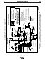
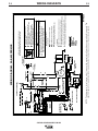
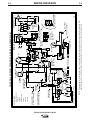
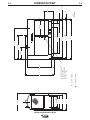
Wiring Diagrams and Dimension Print . . . . . . . . . . . . . . . . . . . . . . . . . . . . . . . . . Section F
Parts Lists . . . . . . . . . . . . . . . . . . . . . . . . . . . . . . . . . . . . . . . . . . . . . . . . . . . . . . .Appendix
SAE-400 WELD’N AIR . . . . . . . . . . . . . . . . . . . . . . . . . . . . . . . . . . . . . . . . . .P303 Series
SAE-400 . . . . . . . . . . . . . . . . . . . . . . . . . . . . . . . . . . . . . . . . . . . . . . . . . . . .P339 Series

A-1
INSTALLATION
SAE400 & SAE400 WELD’N AIR
A-1
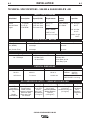
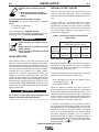
TECHNICAL SPECIFICATIONS - SAE400 & SAE400 WELD’N AIR
Make/Model Description Speed (RPM) Displacement Starting Capacities
System
Perkins 4 cylinder High Idle 1800 256 cu. in
12VDC batteries
Fuel: 22.5 gal.
1004.42 Diesel 71 HP @ Low Idle 1100 (4.2 L)
(2
) & Starter 85.1 L
Engine 1725 RPM Full Load 1725
Bore x Stroke Oil: 8.5 Qts.
8.04 L
3.875” x 5.00”
(98.4 mm x 127.0mm) Coolant: 3.6 gal.
13.63 L
INPUT - DIESEL ENGINE
RATED OUTPUT - WELDER
HEIGHT WIDTH DEPTH WEIGHT
50.13 in. 28.00 in. 83.00 in. SAE400 2125 lbs.
963.9 kg
1273.3 mm 711.2 mm 2108.2 mm SAE400 2428 lbs.
WELD’N AIR 1101.3 kg
OUTPUT - WELDER AND GENERATOR
AIR COMPRESSOR OUTPUT - SAE400 WELD’N AIR ONLY
Duty Cycle
(1)
Welding Output Volts at Rated Amps
60% (NEMA) 400 amps 36 volts
60% (Lincoln Plus) 400 amps 40 volts
Welding Range Open Circuit Voltage Auxiliary Power
80 - 575 Amps 97 Max. OCV 115/230 VAC
@ 1800 RPM 3000 Watts, 60 Hz.
100% Duty Cycle
Make/Model Description Delivery Tank Capacity & Rating Operating Pressure Oil Capacity
IMT 4-cylinder 35 CFM 11 Gallons Loads at 90 P.S.I. 1.33 Quarts
(Iowa Mold Reciprocating, at 100 P.S.I. (41.6 Liters) (6.3 kg/cm
2
) (1.26 Liters)
Tooling/ Diamond Water Cooled, at 60% Maximum Allowable Unloads at 130 P.S.I. IMT’s
Air) Pressure Lubricated Duty Cycle
(1)
Working Pressure (9.1 kg/cm
2
) Synthetic
Aluminum Alloy 991 Liters/min. 150 PSI Compressor
Model Block with Cast- at 7.0 kg/cm
2
(10.5 kg/cm
2
) Oil
DA435ELW Iron sleeves
PHYSICAL DIMENSIONS
(1)
Based on a 10 minute period.

A-2
INSTALLATION
SAE400 & SAE400 WELD’N AIR
A-2
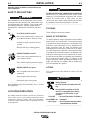
Read this entire installation section before you
start installation.
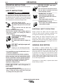
SAFETY PRECAUTIONS
Do not attempt to use this equipment until you have
thoroughly read all operating and maintenance man-
uals supplied with your machine. They include impor-
tant safety precautions, detailed engine starting,
operating and maintenance instructions and parts
lists.
ELECTRIC SHOCK can kill.
•Do not touch electrically live parts such
as output terminals or internal wiring.
•Insulate yourself from the work and
ground.
•Always wear dry insulating gloves.
------------------------------------------------------------------------
ENGINE EXHAUST can kill.
•Use in open, well ventilated areas or
vent exhaust outside
•Do not stack anything near the engine.
------------------------------------------------------------------------
MOVING PARTS can injure.
•Do not operate with doors open or
guards off.
•Stop engine before servicing.
•Keep away from moving parts
------------------------------------------------------------------------
Only qualified personnel should install, use or service
this equipment
LOCATION/VENTILATION
The welder should be located to provide an unrestricted
flow of clean, cool air to the cooling air inlets and to avoid
restricting the cooling air outlets. Also, locate the welder
so that the engine exhaust fumes are properly vented to
an outside area.
DO NOT MOUNT OVER COMBUSTIBLE SURFACES
Where there is a combustible surface directly under
stationary or fixed electrical equipment, that surface
should be covered with a steel plate at least
.06”(1.6mm) thick, which should extend not less than
5.90(150mm) beyond the equipment on all sides.
-----------------------------------------------------------------------
STACKING
These machines cannot be stacked.
ANGLE OF OPERATION
To achieve optimum engine performance the machine
should be run in a level position. The maximum angle
of operation for the air compressor is 20 degrees in all
directions. If the compressor is to be operated at an
angle, provisions must be made for checking and
maintaining the oil level at the normal (FULL) oil capac-
ity in the compressor crankcase. The maximum angle
of operation for the Perkins engine is 30 degrees in all
directions. If the engine is to be operated at an angle,
provisions must be made for checking and maintaining
the oil level at the normal (FULL) oil capacity in the
engine crankcase. When operating the welder at an
angle, the effective fuel capacity will be slightly less
than the specified 22.5 gallons.
LIFTING
The equipment lift bale should be used to lift the
machine.
• Lift only with equipment of adequate
lifting capacity.
• Be sure machine is stable when lift-
ing.
• Do not lift this machine using lift
bale if it is equipped with a heavy
accessory such as trailer or gas
cylinder.
FALLING • Do not lift machine if lift bale is
EQUIPMENT can damaged.
cause injury. • Do not operate machine while
suspended from lift bale.
------------------------------------------------------------------------
WARNING
WARNING
CAUTION

A-3
INSTALLATION
SAE400 & SAE400 WELD’N AIR
A-3
HIGH ALTITUDE OPERATION
At higher altitudes, output derating may be necessary.
As a rule of thumb, derate the welder output 5% for
every 500 meters (1640 ft.) above 1000 meters (3280
ft.).
Contact a Perkins Service Representative for any
engine adjustments that may be required for high alti-
tude operation.
TOWING
The recommended trailers for use with this equipment
for in-plant and yard towing by a vehicle
(1)
are Lincoln’s
K767-1, K956-1 and K956-2. The K956-1 and K956-2
are also designed to be used at highway speeds
(1)
.If
the user adapts a non-Lincoln trailer, he must assume
responsibility that the method of attachment and usage
does not result in a safety hazard nor damage the
welding equipment. Some of the factors to be consid-
ered are as follows:
1. Design capacity of trailer vs. weight of Lincoln
equipment and likely additional attachments.
2. Proper support of, and attachment to, the base of
the welding equipment so that there will be no
undue stress to the trailer’s framework.
3. Proper placement of the equipment on the trailer to
insure stability side to side and front to back when
being moved and when standing by itself.
4. Typical conditions of use, such as travel speed,
roughness of surface on which the trailer will be
operated, and environmental conditions.
5. Proper preventative maintenance of trailer.
6. Conformance with federal, state and local laws.
1
(1)
For highway use, consult applicable federal, state
and local laws regarding specific requirements for
use on public highways, such as brakes, lights, fend-
ers, etc.
VEHICLE MOUNTING
Improperly mounted concentrated loads may cause
unstable vehicle handling and tires or other compo-
nents to fail.
• Only transport this equipment on serviceable vehi-
cles which are rated and designed for such loads.
• Distribute, balance and secure loads so vehicle is
stable under conditions of use.
• Do not exceed maximum rated loads for compo-
nents such as suspension, axles and tires.
• Mount equipment base to metal bed or frame of
vehicle.
• Follow vehicle manufacturer’s instruction.
----------------------------------------------------------------------------
PRE-OPERATION ENGINE AND
COMPRESSOR SERVICE
READ the engine and compressor operating and main-
tenance instructions supplied with this machine.
ENGINE OIL
The engine is shipped with the engine crankcase filled
with high quality SAE 10W-30 oil (API class CD or bet-
ter). Check the oil level before starting the engine. If it is
not up to the full mark on the dip stick, add oil as required.
Check the oil level every four hours of running time during
the first 35 running hours. Refer to the engine Operator’s
Manual for specific oil recommendations and break-in
information. The oil change interval is dependent on the
quality of the oil and the operating environment. Refer to
the engine Operator’s Manual for the proper service and
maintenance intervals.
AIR COMPRESSOR OIL (WELD’N AIR
Only)
The WELD’N AIR is shipped with the compressor filled
with a high quality synthetic compressor oil. If oil is
needed add only Iowa Mold Tooling Co., Inc. (IMT)
synthetic compressor oil until compressor is full.
The use of any other oil causes excessive carbon
build up, and will void the warranty on the com-
pressor.
------------------------------------------------------------------------
Check the oil level daily. Refer to the compressor
Operator’s Manual for the proper service and mainte-
nance intervals.
WARNING
CAUTION

A-4
INSTALLATION
A-4
SAE400 & SAE400 WELD’N AIR
• Stop engine while fueling.
• Do not smoke when fueling.
• Keep sparks and flame away from
tank.
• Do not leave unattended while
fueling.
• Wipe up spilled fuel and allow
fumes to clear before starting
engine.
• Do not overfill tank, fuel
expansion may cause over-
flow.
DIESEL FUEL ONLY
------------------------------------------------------------------------
Fill the fuel tank with clean, fresh diesel fuel. The capac-
ity of the fuel tank is 22.5 gallons (85.1 liters). See engine
Operator’s Manual for specific fuel recommendations.
NOTE:
Before starting the engine, be sure the fuel shut-
off valve on the sediment bowl is open by turning the han-
dle counterclockwise.
ENGINE COOLING SYSTEM
The cooling system has been filled at the factory with
a 50-50 mixture of ethylene glycol antifreeze and
water. Check the radiator level and add a 50-50 solu-
tion as needed. (See Engine Manual or antifreeze
container for alternate antifreeze recommendation.)
ENGINE BREAK-IN PERIOD
Lincoln Electric selects high quality, heavy-duty indus-
trial engines for the portable welding machines we
offer. While it is normal to see a small amount of
crankcase oil consumption during initial operation,
excessive oil use, wetstacking (oil or tar like substance
at the exhaust port), or excessive smoke is not normal.
Larger machines with a capacity of 350 amperes and
higher, which are operated at low or no-load conditions
for extended periods of time are especially susceptible
to the conditions described above. To accomplish suc-
cessful engine break-in, most diesel-powered equip-
ment needs only to be run at a reasonably heavy load
within the rating of the welder for some period of time
during the engine’s early life. However, if the welder is
subjected to extensive light loading, occasional moder-
ate to heavy loading of the engine may sometimes be
necessary. Caution must be observed in correctly
loading a diesel/generator unit.
1. Connect the welder output studs to a suitable resis-
tive load bank. Note that any attempt to short the
output studs by connecting the welding leads
together, direct shorting of the output studs, or con-
necting the output leads to a length of steel will
result in catastrophic damage to the generator and
voids the warranty.
2. Set the welder controls for an output current and
voltage within the welder rating and duty cycle.
Note that any attempt to exceed the welder rating or
duty cycle for any period of time will result in cata-
strophic damage to the generator and voids the
warranty.
3. Periodically shut off the engine and check the
crankcase oil level.
BATTERY CONNECTION
Use caution as the electrolyte is a strong acid that
can burn skin and damage eyes.
Remove and discard the insulating caps from the
negative battery terminals. Attach and tighten neg-
ative battery cable terminals.
NOTE:
This machine is furnished with wet charged
batteries; if unused for several months, the batteries
may require a booster charge. Be careful to charge the
batteries with the correct polarity. Make sure that the
batteries are level while charging.
GASES FROM BATTERY can
explode.
● Keep sparks, flame and cigarettes
away from battery.
-----------------------------------------------------------------------
To prevent EXPLOSION when:
● INSTALLING A NEW BATTERY — disconnect
negative cable from old battery first and
connect to new battery last.
● CONNECTING A BATTERY CHARGER —
remove battery from welder by disconnecting
negative cable first, then positive cable and
battery clamp. When reinstalling, connect
negative cable last. Keep well ventilated.
● USING A BOOSTER — connect positive lead to
battery first then connect negative lead to neg-
ative battery lead at the lower control panel
support.
DIESEL FUEL
can cause fire.
WARNING
WARNING
WARNING

BATTERY ACID can burn eyes and
skin.
● Wear gloves and eye protection
and be careful when working near
battery.
● Follow instructions printed on battery.
IMPORTANT: To prevent ELECTRICAL DAMAGE
WHEN:
a) Installing new batteries.
b) Using a booster.
Use correct polarity — Negative Ground.
To prevent BATTERY BUCKLING, tighten nuts on bat-
teries only until snug. DO NOT OVERTIGHTEN.
• Spark Arrester and Muffler may be
hot!
• Allow engine to cool before servicing
spark arrester!
• Do not operate engine while servicing
spark arrester!
SPARK ARRESTER
Some federal, state or local laws may require that
gasoline or diesel engines be equipped with exhaust
spark arresters when they are operated in certain loca-
tions where unarrested sparks may present a fire haz-
ard. The muffler included with this welder has been
modified and now qualifies as a spark arrester.
Mufflers on machines manufactured before this
change do not qualify as spark arresters and when
required by local regulations, a suitable spark arrestor
must be installed. Spark arresting mufflers will have a
clean out service plug and will have “USDA FS 5100-
1c QUALIFIED SPARK ARRESTER” stamped on the
muffler shell. Any spark arrester must be serviced and
properly maintained.
An incorrect arrester may lead to damage to the
engine or adversely affect performance.
------------------------------------------------------------------------
A-5
INSTALLATION
SAE400 & SAE400 WELD’N AIR
A-5
WELDING OUTPUT CABLES
With the engine off, connect the electrode and work
cables to the studs provided. These connections
should be checked periodically and tightened if neces-
sary.
Listed in Table A.1 are copper cable sizes recom-
mended for the rated current and duty cycle. Lengths
stipulated are the distance from the welder to work and
back to the welder again. Cable sizes are increased
for greater lengths primarily for the purpose of mini-
mizing cable voltage drop.
Table A.1 Combined Length of Electrode and
Work Cables.
MACHINE GROUNDING
Because this portable engine driven welder creates its
own power, it is not necessary to connect its frame to
an earth ground, unless the machine is connected to
premises wiring (home, shop, etc.).
To prevent dangerous electric shock, other equipment
powered by this engine driven welder must:
a) be grounded to the frame of the welder using a
grounded type plug, or
b) be double insulated.
When this welder is mounted on a truck or trailer, its
frame must be securely connected to the metal frame
of the vehicle. When this engine driven welder is con-
nected to premises wiring such as that in a home or
shop, its frame must be connected to the system earth
ground. See the article on grounding in the latest U.S.
National Electrical Code and the local code.
In general, if the machine is to be grounded, it should
be connected with a #8 or larger copper wire to a solid
earth ground such as a metal water pipe going into the
ground for at least ten feet and having no insulated
joints, or to the metal framework of a building which
has been effectively grounded. The U.S. National
Electrical Code lists a number of alternate means of
grounding electrical equipment. A machine grounding
stud marked with the symbol is provided on the
welding generator frame foot.
Up to 100FT.
Up to 31m
2/0 AWG
100-200FT.
31-61m
3/0 AWG
200-250FT.
61-76m
4/0 AWG
AMPS
@60%
Duty Cycle
400
TOTAL COMBINED LENGTH OF ELEC-
TRODE AND WORK CABLES
WARNING
CAUTION

B-1
OPERATION
B-1
WELDING SPARKS can cause
fire or explosion.
• Do not weld near flammable material .
• Do not weld on containers that have
held flammable material.
-----------------------------------------------------------
MOVING PARTS can injure.
• Keep away from moving parts
• Do not operate with doors open or
guards off.
• Stop engine before servicing.
------------------------------------------------------------------------
ENGINE EXHAUST can kill.
• Use in open, well ventilated areas or
vent exhaust outside.
------------------------------------------------------------------------
ADDITIONAL SAFETY PRECAUTIONS
Always operate the welder with the hinged doors
closed as these provide maximum protection from
moving parts and insure proper cooling air flow.
Read carefully the Safety Precautions page in the
Instruction Manual before operating this machine.
Always follow these and any other safety procedures
included in this manual and in the engine and com-
pressor instruction manuals.
GENERAL DESCRIPTION
The SAE400 or SAE400 WELD’N AIR is a diesel
engine driven welding power source. The machine
uses a DC generator for DC stick electrode welding
and an AC exciter for 115/230 VAC auxiliary power. As
a generator it can supply up to 3,000 watts of 115/230
volt AC power. As a welder it provides up to 575 amps
of DC constant current output. The belt driven air com-
pressor of the SAE400 WELD’N AIR provides 35 CFM
at 100 PSI compressed air.
The engine is a 71 Hp (54kw), 4-cylinder water cooled
diesel made by Perkins.
OPERATING INSTRUCTIONS
Read and understand this entire section before operat-
ing your equipment.
SAFETY INSTRUCTIONS
Do not attempt to use this equipment until you have
thoroughly read all operating and maintenance manu-
als supplied with your machine. They include important
safety precautions, detailed engine starting, operating
and maintenance instructions and parts lists.
ELECTRIC SHOCK can kill.
• Do not touch electrically live parts or
electrodes with your skin or wet cloth-
ing.
• Insulate yourself from the work and
ground.
• Always wear dry insulating gloves.
• Do not use AC welder if your clothing, gloves or
work area is damp or if working on, under or
inside workpiece.
Use the following equipment:
• Semiautomatic DC constant voltage
(wire) welder.
• DC manual (stick) welder.
• AC welder with reduced voltage con-
trol.
------------------------------------------------------------------------
ARC RAYS can injure eyes and
burn skin.
• Wear eye, ear, and body protection.
----------------------------------------------------------
• Only qualified personnel should install, use or
service this equipment.
• Consult instruction manual before operating.
----------------------------------------------------------------------
Before operating, read and understand the manu-
facurer’s instructions for this equipment and the
consumables to be used including the Material
Safety Data Sheet (MSDS) and follow your
employer’s safety practices.
------------------------------------------------------------------------
FUMES AND GASES can be dangerous to
your health.
• Keep your head out of fumes.
• Use enough ventilation or exhaust at the arc, or
both, to keep the fumes and gases from your
breathing zone and general area.
SAE400 & SAE400 WELD’N AIR
WARNING

B-2
OPERATION
B-2
RECOMMENDED APPLICATIONS
WELDER
The SAE400 or SAE400 WELD’N AIR provides excel-
lent constant current DC welding output for stick
(SMAW) welding. The field installed optional CV
Adapter (K385-1) provides up to 500 amps at 35 volts
of constant voltage output for semiautomatic welding.
AUXILIARY POWER
The SAE400 or SAE400 WELD’N AIR provides 3 KW
of 115/230 VAC output for auxiliary power and emer-
gency standby power.
COMPRESSED AIR
The SAE400 WELD’N AIR only, provides 35 CFM at
100 PSI compressed air for air arc gouging and air
powered tools.
PRODUCT APPLICATION
TOOL CFM - L/min PSI - kg/cm
2
Arc Gouging, 3/8 in. (9.5)mm Electrode 16 453 18 1.27
(Current Range, 350-600 amps DC)
Grinder, 2 in. (50.8mm) wheel 14-20 396-566 90 6.33
Chipping Hammer- Weight: 18lbs. (8.1kg.) 28-30 793-850 90 6.33
Air or Impact Wrenches: 1/2 in. to 3/4 in. (12.7-19.1mm) 30 850 90 6.33
Paint Sprayer 2-20 57-566 90 6.33
Drills Capacity 3/8 in. (9.5mm) 20-40 566-1133 90 6.33
Sand Blaster - 1/8 in. (3.2 mm) Nozzle diameter 26 736 100 7.03
DESIGN FEATURES AND ADVANTAGES
FOR STICK WELDING
• Excellent DC constant current output for stick weld-
ing applications.
• Continuous adjustment of both voltage and current
for unsurpassed welds on demanding jobs.
• Remote control capability standard.
FOR AUXILIARY POWER
• 3,000 watts of 115/230 VAC, 60 Hz auxiliary power.
• One 20 amp 115 VAC duplex receptacle for up to 26
amps of 115 VAC power.
• One 15 amp, 230 VAC duplex receptacle for up to 13
amps of 230 VAC power.
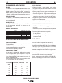
• Weld and AC auxiliary power at the same time (with-
in the limits shown on the chart below).
OTHER FEATURES
• Perkins 4-cylinder, water cooled diesel engine.
Designed for long life, easy maintenance and excel-
lent fuel economy.
• Engine protection system shuts the engine down for
low engine oil pressure or high coolant temperature.
• Electronic Engine Idler. Engine automatically goes
to low idle in 10 to 14 seconds after welding or use
of auxiliary power stops. Includes high idle switch.
• Gauges for engine oil pressure, coolant temperature
and battery charging ammeter.
• Engine hour meter standard.
• Extended range 22.5 gallon (85.1 L) fuel tank.
FOR COMPRESSED AIR (SAE400 WELD’N AIR only)
• 35 CFM at 100 PSI for air arc gouging and air pow-
ered tools.
• 11 Gallon air receiver tank system with integral over-
pressure relief valve for smooth air delivery.
• Indicator light for compressor operation.
• Gauges for compressor air pressure and compres-
sor oil pressure.
• No welding output derating required at maximum
compressor load.
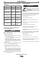
DUTY CYCLE
Duty cycle is based on a ten minute period and opera-
tion in an ambient temperature of 104°F(40°C).
The SAE400 & SAE400 WELD’N AIR are NEMA rated
at 60% duty cycle. Duty cycle is based on a ten minute
period. Therefore, a 60% duty cycle welder can be
operated at nameplate rated output for 6 minutes out of
every 10 minute period without overheating.
The auxiliary power can be used continuously (100%
duty cycle) within its rated current capacities.
The air compressor on the SAE400 WELD’N AIR is
rated at a 60% duty cycle based on a ten minute peri-
od as described above.
SAE400 & SAE400 WELD’N AIR
Welding Using Only Using Only Total
Current, Amps 115V Circuit, 230V Circuit, Aux.
@ NEMA Arc Amps Amps kVA
Volts
0 26 13 3.0
100 19.5 9.75 2.25
200 13 6.5 1.5
300 6.5 3.25 0.75
400 0 0 0

B-3
OPERATION
B-3
ENGINE CONTROLS
IGNITION SWITCH
When placed in the “ON” position, this switch ener-
gizes the fuel solenoid. When placed in the “OFF” posi-
tion, the flow of fuel to the injection pump is stopped to
shut down the engine.
“IDLER” SWITCH
The idler switch has two positions, “HIGH” and
“AUTO”.
When in “HIGH” ( ) position, the engine will run
continuously at high idle.
When in “AUTO” ( / ) idle position, the idler
operates as follows:
a. Welding
When the electrode touches the work, the welding
arc is initiated and the engine accelerates to full
speed.
After welding ceases (and no auxiliary power is
being drawn), the engine will return to low idle after
approximately 10 to 14 seconds.
b. Auxiliary Power
With the engine running at low idle and auxiliary
power for lights or tools is drawn (approximately
100-150 watts or greater) from the receptacles, the
engine will accelerate to high speed. If no power is
being drawn from the receptacles ( and not weld-
ing) for 10-14 seconds, the idler reduces the engine
speed to low idle.
ENGINE TEMPERATURE GAUGE
Displays the coolant temperature in the engine block.
ENGINE OIL PRESSURE GAUGE
Displays the oil pressure to the engine. When the
engine starts running, watch for the oil pressure to
build up. If no pressure shows within 30 seconds, stop
the engine and consult the engine instruction manual.
BATTERY CHARGING AMMETER
Displays the current going from the charging alternator
into the batteries. It is normal for charging current to be
high (above 15 amps) after starting or when the batter-
ies are ‘low’ on charge.
ENGINE HOUR METER
The engine hour meter records the total running time
on the engine in hours. It can be used to keep a record
of maintenance on the engine and or welder.
ENGINE PROTECTION SYSTEM
The engine protection system shuts down the engine
under high coolant temperature or low engine oil pres-
sure conditions by allowing the fuel solenoid valve to
close.
WELDER CONTROLS
POLARITY SWITCH
Turn the Arc Polarity switch to electrode positive or
electrode negative as required for each particular
application.
CONTROL OF WELDING CURRENT
Purpose of Controls
The continuous “Current Control” is the main current
adjuster. The “Job Selector” is both a fine current
adjuster and the continuous Open Circuit Voltage
adjuster. Open Circuit Voltage (OCV) controls the arc
characteristics.
“Job Selector”
The “Job Selector” dial is divided into four colored sec-
tions providing OCV ranges as follows:
Color Title OCV Range
White Large Electrodes High OCV
Black Normal Welding Medium OCV
Red Overhead & Vertical Low OCV
Grey Special Applications Extra-Low OCV
The “Job Selector” is usually set in the black range
because it provides a soft “Buttering “ arc desired for
most welding. Some operators prefer to set the “Job
Selector” in the red range for a snappy “Digging” arc
when welding vertical up or overhead.
“Current Control”
Do not adjust the “Current Control” while welding
because this can damage the control.
------------------------------------------------------------------------
The “Current Control” dial is calibrated in amperes on
three separate colored dials corresponding to the
white, black and red ranges of the “Job Selector” dial.
For example: when the “Job Selector” is set on the
black range, the approximate welding current is indi-
cated on the black scale of the “Current Control” dial.
SAE400 & SAE400 WELD’N AIR
CAUTION

B-4
OPERATION
B-4
How to Set the Controls
Assume you want a normal soft arc and about 135
amps, using a 5/32” (4.0 mm) electrode:
1. Set the “Job Selector” at the center of the black
range.
2. Set the “Current Control” to read 135 amps on the
black dial.
3. Start to weld.
4. If you want a little more current, turn the “Job
Selector” up (counterclockwise) to increase cur-
rent. If you want a little less current, turn the “Job
Selector” down (clockwise) to decrease current.
5. If dialing the desired current with the “Job
Selector” moves the setting outside the black
range causing undesirable arc characteristics, turn
the “Job Selector” back to the center of the black
range. Then turn the “Current Control” up or down
a little as needed. Readjust the “Job Selector” for
the exact characteristics and current desired.
REMOTE CONTROL
A receptacle and “Local/Remote” control switch on the
lower front control panel and a remote control box with
100 ft. (30.5 m) of cord for adjusting the OCV at the
welding site are standard. Putting the switch in the
“REMOTE” position allows fine current control at the
remote control box while placing the switch in the
“LOCAL” position allows fine current control at the “Job
Selector” on the machine. When using the optional
field installed CV adapter (K385-1) the “Local/Remote”
switch is only active in the “VV” mode.
AUXILIARY POWER CONTROLS
115 VAC Receptacle
One 20 amp, 115 VAC duplex receptacle provides 115
VAC for auxiliary power. A total of 26 amps can be
drawn from this receptacle.
230 VAC Receptacle
One 15 amp, 230 VAC duplex receptacle provides 230
VAC for auxiliary power. A total of 13 amps can be
drawn from this receptacle.
Circuit Breakers
The circuit breakers provide separate overload current
protection for each half of the 115 V duplex receptacle.
The circuit breakers provide overload current protec-
tion in both current carrying wires of the 230 V duplex
receptacle.
Ground Stud
Provides a connection point for connecting the
machine to earth ground. For the safest grounding pro-
cedure refer to “Machine Grounding” in the INSTALLA-
TION section of this manual.
AIR COMPRESSOR CONTROLS -
(SAE400 WELD’N AIR ONLY)
COMPRESSOR ON/OFF SWITCH
Placing the “ON/OFF” switch in the “ON” position
allows the “pressure switch” (factory preset) to control
the air compressor through an electric clutch. When
the system pressure falls below 90 psi, the “pressure
switch” engages the clutch and compressor. When the
system pressure goes above 130 psi, the “pressure
switch” disengages the clutch and compressor.
The “ON/OFF” switch needs to be in the “ON” position
when using compressed air. When placed in the “OFF”
position this switch does not allow the compressor
clutch to engage regardless of the tank pressure.
The “ON/OFF” switch should be in the “OFF” position
while starting the engine. This will minimize the load on
the starter motor.
COMPRESSOR OPERATING LIGHT
This light is on when the compressor “ON/OFF” switch
is in the “ON” position.
COMPRESSOR AIR PRESSURE GAUGE
This gauge displays the air pressure in the air receiver
tanks.
COMPRESSOR OIL PRESSURE GAUGE
This gauge displays the compressor oil pressure. Oil is
under pressure only when the compressor clutch is
engaged.
SAE400 & SAE400 WELD’N AIR

B-5
OPERATION
B-5
ENGINE OPERATION
Do not adjust the high idle engine speed (rpm) above
the factory setting specification as this will overspeed
the air compressor and void it’s warranty.
------------------------------------------------------------------------
STARTING INSTRUCTIONS
Be sure all Pre-Operation Maintenance has been per-
formed. (See INSTALLATION section of this manual).
Set the air compressor “ON/OFF” switch in the “OFF”
position. To start the engine, place ignition toggle
switch in the “ON” position. Engage the starter button.
When the engine starts running, observe the engine oil
pressure. If no pressure shows within 30 seconds,
stop the engine and consult the engine operating man-
ual. To stop the engine, place the ignition toggle switch
in the “OFF” position.
When an engine is started for the first time, some of
the oil will be needed to fill the passages of the lubri-
cating system. Therefore, on initial starting, run the
engine for about five minutes and then stop the engine
and recheck the oil. If the level is down, fill to the full
mark again. The engine controls were properly set at
the factory and should require no adjusting when
received.
For added safety always operate the welder with the
doors closed. Further, leaving the doors open changes
the designed air flow and may cause engine, genera-
tor or compressor overheating.
COLD WEATHER STARTING
Never use any other starting aids, such as ether,
when using the “Thermostart” system.
------------------------------------------------------------------------
When overnight temperatures are between 10°F (-
12°C) and freezing, use the standard “Thermostart”
starting system installed on all engines. Follow the
instructions on the start panel nameplate and in the
engine manual shipped with the welder. With fully
charged batteries and the proper weight oil, the
“Thermostart” system operates satisfactorily even
down to about 0°F (-18°C).
AIR COMPRESSOR (SAE400 WELD’N AIR only)
Cylinder head stud torque must be checked after initial
8 to 10 hours of operation. See compressor operator’s
manual for details. Compressor mounting bolts should
be checked for tightness after initial 8 to 10 hours of
operation.
TYPICAL FUEL CONSUMPTION
The typical fuel consumption of the SAE400 and
SAE400 WELD’N AIR for various operating scenarios
is shown below:
Low Idle - No Load .35 gal./ hr.
1100 RPM (1.32 L./hr.)
High Idle - No Load .75 gal./hr.
1800 RPM (2.84 L./hr.)
Welding Load 1.92 gal./hr.
400 Amps, 40 Volts (7.27 L./hr.)
Auxiliary Power .96 gal./hr.
3000VA (3.63 L./hr.)
Air Compressor 1.04 gal./hr.
(SAE400 WELD’N AIR Only) (3.94 L./hr.)
400 Amps, 40 Volts Load 2.22 gal./hr.
with Air Compressor “ON” (8.40 L./hr.)
(SAE400 WELD’N AIR Only)
Auxiliary Power 1.20 gal./hr.
3000 VA with (4.54 L./hr.)
Air Compressor “ON”
(SAE400 WELD’N AIR Only)
SAE400 & SAE400 WELD’N AIR
WARNING
CAUTION

C-1
ACCESSORIES
C-1
K930-2 Hi-Freq™ - Provides high frequency plus a
gas valve for TIG welding. A water valve is available as
an option. Requires 115 volt AC input. (Limited to 250A
- 60% Duty Cycle).
K802-D Power Plug Kit - Kit includes male plugs for
each auxiliary receptacle.
K767-1 Trailer - A 4-wheel steerable trailer for in-plant
and yard towing
(1)
with E78-14 load range (B) tubeless
tires. Mounts directly to welder base.
K956-1Trailer - A 2-wheel trailer designed for road
(1)
,
off road, in-plant and yard towing. Trailer mounts
directly to welder base.
1
For highway use, consult applicable federal, state and local laws regarding
possible requirements for brakes, lights, fenders, etc.
Pipe Thawing with an arc welder can cause fire,
explosion, damage to electric wiring or to the arc
welder if done improperly. The use of an arc
welder for pipe thawing is not approved by the
CSA, nor is it recommended or supported by
Lincoln Electric.
------------------------------------------------------------------------
K704 Standard Accessory Kit - Includes electrode
and work cables, headshield, work clamp and elec-
trode holder.
K385-1 CV Adapter - Provides constant voltage output
for semiautomatic welding. (Field installation only).
K2144-1 Oil Drain Kit - Includes ball valve, hose and
clamp.
K1847-1 Spark Arrestor Kit
K1690-1 GFCI RECEPTACLE KIT
Includes one UL approved 120V ground fault circuit
interrupter duplex type receptacle with cover and
installation instructions. Replaces the factory installed
120V duplex receptacle. Each receptacle of the GFCI
Duplex is rated at 20 Amps, the maximum total current
from the GFCI Duplex is limited to the 20 Amps. Two
kits are required.
K2303-1 SHEET METAL KIT- For SAE400 model
K1278-5.
SAE400 & SAE400 WELD’N AIR
WARNING
La page est en cours de chargement...
La page est en cours de chargement...
La page est en cours de chargement...
La page est en cours de chargement...
La page est en cours de chargement...
La page est en cours de chargement...
La page est en cours de chargement...
La page est en cours de chargement...
La page est en cours de chargement...
La page est en cours de chargement...
La page est en cours de chargement...
La page est en cours de chargement...
La page est en cours de chargement...
La page est en cours de chargement...
La page est en cours de chargement...
La page est en cours de chargement...
La page est en cours de chargement...
-
 1
1
-
 2
2
-
 3
3
-
 4
4
-
 5
5
-
 6
6
-
 7
7
-
 8
8
-
 9
9
-
 10
10
-
 11
11
-
 12
12
-
 13
13
-
 14
14
-
 15
15
-
 16
16
-
 17
17
-
 18
18
-
 19
19
-
 20
20
-
 21
21
-
 22
22
-
 23
23
-
 24
24
-
 25
25
-
 26
26
-
 27
27
-
 28
28
-
 29
29
-
 30
30
-
 31
31
-
 32
32
-
 33
33
-
 34
34
-
 35
35
-
 36
36
-
 37
37


Lincoln Electric SAE-400 Mode d'emploi
- Catégorie
- Système de soudage
- Taper
- Mode d'emploi
dans d''autres langues
Documents connexes
-
Lincoln Electric IM581 Manuel utilisateur
-
-
-
-
-
-
Lincoln Electric Ranger 305D Mode d'emploi
-
-
-