Miller INTELLIMATIC DS-12M Le manuel du propriétaire
- Catégorie
- Système de soudage
- Taper
- Le manuel du propriétaire
Ce manuel convient également à

October
1986
FORM:
OM-1552
Effective
With
Serial
No.
JG025177
INTELLIMATICTM
DS-12M
DS-16M
OWNERS
MANUAL
millER
MILLER
ELECTRIC
MFG.
CO.
718
S.
BOUNDS
SI,
P.O.
Box
1079
APPLETON,
WI
54912
USA
IMPORTANT
_________
Read
and
understand
the
entire
contents
of
both
this
manual
and
the
power
source
manual
used
with
this
unit,
with
special
emphasis
on
the
safety
material
throughout
both
manuals,
before
installing,
operating,
or
maintaining
this
equipment.
This
unit
and
these
Instructions
are
for
use
only
by
persons
trained
and
experienced
In
the
safe
operation
of
welding
equipment.
Do
not
allow
untrained
persons
to
install,
operate,
or
maintain
thi.
unit.
Contact
your
distributor
if
you
do
not
fully
understand
these
instructions.
PRINTED
IN
U.S.A.

LIMITED
WARRANTY
EFFECTIVE:
FEBRUARY
25,
1985
This
warranty
supersedes
all
previous
MILLER
warranties
and
is
ex
clusive
with
no
other
guarantees
or
warranties
expressed
or
implied.
LIMITED
WARRANTY
-
Subject
to
the
terms
and
condi-
In
the
case
of
Millers
breech
of
warranty
or
any
other
duty
~..
~
tions
hereof,
Miller
Electric
Mfg.
Co.,
Appleton.
Wisconsin
with
respect
to
the
quality
of
any
goods,
the
exclusive
remedies
~
~
warrants
to
its
Distributor/Dealer
that
all
new
and unused
therefore
shall
be,
at
Millers
option
(1)
repair
or
(2)
replacement
~,
~
Equipment
furnished
by
Miller
is
free
from
defect
in
workman-
or,
where
authorized
in
witting
by
Miller
in
appropriate
cases,
(3)
~
ship
and
material
as
of
the
time
and
place
of
delivery
by
Miller.
the
reasonable
cost
of
repair
or
replacement
at
an
authorized
No
warranty
is
made
by
Miller
with
r~pect
to
engines,
trade
Miller
service
station
or
(4)
payment
at
or
credit
for
the
purchase
~
~
accessories
or
other
items
manufactured
by
others.
Such
price
(lees
reasonable
depreciation
based
upon
actual
use)
upon
~
~
engines,
trade
accessories
and
other
items
are
sold
subject
to
return
of
the
goods
at
Customers
risk
and
experiee.
MILLERs
the
warranties
of
their
respective
manufacturers,
if
any
.
A)l
option
of
repair
or
replacement
will
be
F.O.B.,
Factory,
at
engines
are
warranted
by
their
manufacturer
for
one
year
from
Appleton,
Wieconsin,
or
F.O.B.,
at
a
MILLER
authorized
service
date
of
original
purchase,
except
Tecumseh
engines
which
facility,
therefore,
no
con~perieation
for
transportation
costs
of
~
have
a
two
year
warranty.
any
kind
will
be
allowed.
Upon
receipt
of
notice
of
apparent
defect
or
failure,
Miller
shall
instiuct
the
claimant
on
the
warranty
4
Except
as
specified
below,
Millers
warranty
does
not
apply
claim
procedures
to
be
followed.
to
components
having
normal
useful
life
of
less
than
one
(1)
year,
such
as
spot
welder
tips,
relay
and
contactor
points,
MILLERMATIC
parts
that
come
in
contact
with
the
welding
ANY
EXPRESS
WARRANTY
NOT
PROVIDED
HEREIN
AND
f
,j)
wire
including
nozzles
and
nozzle
insulators
where
failure
does
ANY
IMPLIED
WARRANTY,
GUARANTY
OR
REPRESENTA
r.
not
result
from
defect
in
workmanship
or
material.
lION
AS
TO
PERFORMANCE,
AND
ANY
REMEDY
FOR
BREACH
OF
CONTRACT
WHICH,
BUT
FOR
THIS
PROVISION,
~
Miller
shall
be
required
to
honor
warranty
claims
on
war-
MIGHT
ARISE
BY
IMPUCAT1ON,
OPERATION
OF
LAW,
~
~
ranted
Equipment
inthe
event
of
failure
resulting
from
a
defect
CUSTOM
OF
TRADE
OR
COURSE
OF
DEAUNG,
INCLUDING
~.
~
within
the
following
periods
from
the
date
of
delivery
of
Equip-
ANY
IMPLIED
WARRANTY
OF
MERCHANTABIUTY
OR
OF
fr~
ment
to
the
original
user:
FITNESS
FOR
PARTICULAR
PURPOSE,
WITh
RESPECT
TO
~..
ANY
AND
ALL
EQUIPMENT
FURNISHED
BY
MILLER
IS
EX
1.
Arc
welders,
power
sources
and
components
....
1
year
CLUDED
AND
DISCLAIMED
BY
MILLER.
2.
Original
main
power
rectifiers
3
years
(labor
-1
year
only)
3.
AIwelding~ins,eeder/andpIst~tu.Ji~...
90daye
EXCEPT
AS
EXPRESSLY
PROVIDED
BY
MILLER
IN
*
4.
All
other
Millermatic
Feeders
1
year
WRITING,
MILLER
PRODUCTS
ARE
INTENDED
FOR
5.
Replacement
or
repair
parts,
exclusive
of
labor..
60
days
ULTIMATE
PURCHASE
BY
COMMERCIAL/INDUSTRIAL
6.
Batteries
6
months
USERS
AND
FOR
OPERATION
BY
PERSONS
TRAINED
AND
EXPERIENCED
IN
THE
US~
,.ND
MAINTENANCE
OF
~r
provided
that
Miller
is
notified
in
writing
within
thirty
(30)
days
WELDING
EQUIPMENT
AND
NOT
FOR
CONSUMERS
OR
of
the
date
of
such
failure.
CONSUMER
USE.
MILLERS
WARRANTIES
DO
NOT
EXTEND
~
TO,
AND
NO
RESELLER
IS
AUTHORIZED
TO
EXTEND
As
a
matter
of
general
policy
onty,
Miller
may
honor
claims
MILLERS
WARRANTIES
TO
ANY
CONSUMER
~\\
submitted
by
the
original
user
within
the
foregoing
periods.
it
.
.
~
ji~
~,
j1~.
~
...
.
.

ERRATA
SHEET
After
this
manual
was
printed,
refinements
in
equipment
design
occurred.
This
sheet
lists
exceptions
to
data
appearing
later
in
this
manual.
AMENDMENT
TO
SECTION
3-
INSTALLATION
Replace
Sections
3-4
and
3-6
with
the
following:
INSTALLATION
OF
OPTIONAL
WIRE
REEL
AND
REEL-TYPE
WIRE
(Figure
3-3)
The
following
procedure
applies
to
both
the
left
and
right
sided.
1.
Remove
retaining
ring
and
if
applicable
wire
reel
assembly
from
hub.
2.
Lay
wire
reel
assembly
flat
on
a
table
or
floor.
3.
Remove
spanner
nut
from
wire
reel
assembly.
4.
Remove
wire
retainer,
and
install
wire
onto
wire
reel.
Be
sure
that
wire
feeds
off
top
of
reel.
5.
Reinstall
wire
retainer
and
spanner
nut
onto
wire
reel.
6.
Slide
wire
reel
assembly
onto
hub,
and
rotate
assembly
until
hub
guide
pin
is
seated
in
reel.
7.
Reinstall
retaining
nng
onto
hub.
Amend
Figure
3-3.
Reel
Installation
Sp.nnst
18-Oei
755-A
Ri~insr
R..l
Hub
pin
Figure
3-3.
Reel
Installation

a*First
digit
represents
page
no
-
digits
following
dash
represent
item
no.
BE
SURE
TO
PROVIDE
MODEL
AND
SERIAL
NUMBER
WHEN
ORDERING
REPLACEMENT
PARTS.
Dia.
Mkgs.
Part
No.
Replaced
With
Descnption
Quantity
6-21
PC3
097
180
121
436
CIRCUIT
CARD,
interface
(Eff
w/JJ365634
thru
JJ405391)
.
..
1
6-21
PC3
121
436
121
472
CIRCUIT
CARD,
interface
(Eff
w/JJ405392
&foUowing)
1
11-10
056416
108
008
108
861
108858
108
857
REEL,
wire
(consisting
of)
NUT,
spanner-spool
RETAINER,
spool-support
SUPPORT,
reel
support
1
1
1
1
0M1552
Page
2

TABLE
OF
CONTENTS
Section
No.
Page
No.
SECTION
1
-
SAFETY
RULES
FOR
OPERATION
OF
ARC
WELDING
POWER
SOURCE
1
-
1.
Introduction
1
1
-
2.
General
Precautions
1
1
-3.
ArcWelding
7
1
-
4.
Standards
Booklet
Index
11
SECTION
2
-
INTRODUCTION
2
-
1.
General
Information
And
Safety
13
2
-
2.
Receiving-Handling
13
2
-
3.
Description
13
SECTION
3
-
INSTALLATION
3
-
1.
Location
And
Assembly
14
3
-2.
InstallationOfWireSupport
15
3
-
3.
Reinstallation
Of
Hub
Assembly
16
3
-
4.
Installation
Of
Wire
Reel
(Optional)
16
3
-
5.
Installation
Of
Spool-Type
Wire
16
3
-
6.
Installation
Of
Reel-Type
Wire
16
3
-7.
Drive
Motor
17
3
-
8.
Drive
Roll
And
Wire
Guide
Installation
17
3
-
9.
Water
Connections
(Optional)
18
3-10.
Welding
Gun
Connections
18
3-11.
Shielding
Gas
Connections
20
3-12.
Motor
Control
Connection
20
3-13.
Gun
Trigger
Connections
20
3-14.
Weld
Cable
Connections
20
3-15.
Voltage
Sensing
Connections
21
3-16.
SafetyCollarRemoval
21
3-17.
BoomAdjustments
21
3-18.
Internal
Program
Options
22
3-19.
Wire
Feeder-Welding
Power
Source
Interface
Connection
24
3-20.
Adjustment
Of
Hub
Tension
24
3-21.
Pulley
Adjustment
24
3-22.
Welding
Wire
Threading
24
SECTION
4
-
OPERATOR
CONTROLS
4-1.
PowerSwitch
26
4
-
2.
Key-Switch
26
4
-
3.
Program
Select
Push
Button
26
4
-
4.
Program
Indicator
Lights
26
4
-
5.
Left
And
Right
Trigger
Indicator
Lights
26
4
-
6.
Sequence
Advance/Contactor
Push
Button
26
4
-
7.
Program
Sequence
Indicator
Lights
26
4
-
8.
Contactor
On
Indicator
Light
26
4
-
9.
Purge/Amps/CV-CC
Push
Button
26
4-10.
Jog/Hours
Push
Button
27
4-11.
VoltsNumericDisplay
27
4-12.
Volts
Indicator
Light
27
4-13.
Volts
Increase
And
Decrease
Push
Buttons
27
4-14.
Wire
Speed/Amps
Numeric
Display
27

Section
No.
Page
No.
SECTION.4
-
OPERATOR
CONTROLS
(ONTD)
4-15.
Inches
Indicator
Light
27
4-16.
Meters
Indicator
Light
27
4-17.
Amps
Indicator
Light
27
4-18.
Wire
Speed/Amps
Increase
And
Decrease
Push
Buttons
28
4-19.
Time
Numeric
Display
28
4-20.
Seconds
Indicator
Light
28
4-21.
Cycles
Indicator
Light
28
4-22.
Hours
Indicator
Light
28
4-23.
Time
Increase
And
Decrease
Push
Buttons
28
SECTION
5
-
PRESETTING
SEMIAUTOMATIC
WELDING
PROGRAMS
5
-
1.
Definition
Of
Terms
29
5
-
2.
Presetting
Semiautomatic
Welding
Programs
29
SECTION
6
-
SEQUENCE
OF
OPERATION
6
-
1.
Normal
Welding
Without
Dual
Scheduling
30
6
-
2.
Dual
Scheduling
By
Means
Of
The
Gun
Trigger
31
6
-
3.
Timed
Welds
32
6
-
4.
Shutting
Down
33
SECTION
7
-
MAINTENANCE
b
TROUBLESHOOTING
7
-
1.
Inspection
And
Upkeep
33
7
-
2.
Cleaning
Of
Drive
Rolls
33
7
-
3.
Motor
Overload
Breaker
33
7
-
4.
Brush
Inspection
And
Replacement
34
7
-
5.
Drive
Shaft
Inspection
And
Maintenance
34
7
-
6.
Diagnostic
Displays
36
7
-
7.
Microprocessor
Battery
36
7
-
8.
Clearing
The
Weld
Program
Memory
(RAM)
36
7
-
9.
Troubleshooting
Chart
36

SECTION
1
-
SAFETY
RULES
FOR
OPERATION
OF
ARC
WELDING
POWER
SOURCE
SECTION
1
-
REGLES
DE
SECURITE
POUR
LE
FONCTIONNEMENT
DU
POSTE
DE
SOUDAGE
A
LARC
1-1.
INTRODUCTION
-
We
learn
by
experience.
Learning
safety
through
personal
experience,
like
a
child
touching
a
hot
stove
is
harmful,
wasteful,
arid
un
wise.
Let
the
experience
of
others
teach
you.
Safe
practices
developed
from
experience
in
the
use
of
welding
and
cutting
are
described
in
this
manual.
Research,
development,
and
field
experience
have
evolved
reliable
equipment
and
safe
installation,
opera
tion,
and
servicing
practices.
Accidents
occur
when
equipment
is
improperly
used
or
maintained.
The
reason
for
the
safe
practices
may
not
always
be
given.
Some
are
based
on
common
sense,
others
may
require
technical
volumes
to
explain.
It
is
wiser
to
follow
the
rules.
Read
and
understand
these
safe
practices
before
at
tempting
to
install,
operate,
or
service
the
equipment.
Comply
with
these
procedures
as
applicable
to
the
par
ticular
equipment
used
and
their
instruction
manuals,
for
personal
safety
and
for
the
safety
of
others.
Failure
to
observe
these
safe
practices
may
cause
serious
injury
or
death.
When
safety
becomes
a
habit,
the
equipment
can
be
used
with
confidence.
These
safe
practices
are
divided
into
two
Sections:
1
-
General
Precautions,
common
to
arc
welding
and
cutting;
and
2
-
Arc
Welding
(and
Cutting)
(only).
Reference
standards:
Published
Standards
on
safety
are
also
available
for
additional
and
more
complete
pro
cedures
than
those
given
in
this
manual.
They
are
listed
in
the
Standards
Index
in
this
manual.
ANSI
Z49.1
is
the
most
complete.
The
National
Electrical
Code,
Occupational
Safety
and
Health
Administration,
local
industrial
codes,
and
local
inspection
requirements
also
provide
a
basis
for
equip
ment
installation,
use,
and
service.
1-2.
GENERAL
PRECAUTIONS
Different
arc
welding
processes;
electrode
alloys,
and
fluxes
can
produce
different
fumes,
gases,
and
radiation
levels.
In
addition
to
the
information
in
this
manual,
be
sure
to
consult
flux
and
elec
trode
manufacturers
for
specific
technical
data
and
precautionary
measures
concerning
their
material.
A.
Burn
Prevention
Wear
protective
clothing
-
gauntlet
gloves
designed
for
use
in
welding,
hat,
and
high
safety-toe
shoes.
Button
shirt
collar
and
pocket
flaps,
and
wear
cuffless
trousers
to
avoid
entry
of
sparks
and
slag.
Wear
helmet
with
safety
goggles
or
glasses~
with
side
shields
underneath,
appropriate
filter
lenses
or
plates
(protected
by
clear
cover
glass).
This
is
a
MUST
for
welding
or
cutting,
(and
chipping)
to
protect
the
eyes
1-1.
INTRODUCTION
-
Contrairement
a
lappren
tissage
de
Ia
vie,
Iapprentissage
de
Ia
sØcuritØ
par
ex
pØrience
personnelle,
comme
lenfant
gui
touche
un
poŒle
chaud,
est
dangereux,
imprudent
et
inutile.
lnstruisez-vous
donc
de
lexpØrience
dautrui.
Des
mØthodes
de
sØcuritØ
issues
de
lexpØrience
du
soudage
et
du
coupage
sont
dØcrites
dans
le
manuel.
La
recherche,
le
progres
et
lexpØrience
dans
ce
domaine
ont
dØveloppØ
un
materiel
fiable
et
des
mØthodes
de
sØcuritØ
pour
linstallation,
Ia
fonctionnement
et
lentre
tiØn.
Des
accidents
se
produisent
Iorsque
le
matØrial
est
inadequatement
utilisØ
ou
entretenu.
La
raison
de
ces
mØthodes
de
sØcuritØ
peut
ne
pas
Œtre
toujours
donnØe.
Certaines
sont
fondØes
sur
le
sens
commun,
dautres
demanderont
a
Œtre
expliquØes
par
des
livres
techni~
ques.
II
est
plus
sage
de
suivre
las
rØgles.
Lisez
et
comprenez
ces
mØthodes
de
sØcuritØ
avant
dessayer
dinstaller,
de
faire
fonctionner
ou
de
rØparer
lappareil.
Pour
votre
sØcuritØ
personnelle
et
celia
dautrui,
conformez-vous
a
ces
regies
at
aux
manuels
dinstructions.
Manquer
dobserver
ces
mØthodes
de
sØcuritØ
pourrait
entrainer
des
blessures
graves
ou
mŁme
Ia
mort.
Quand
Ia
sØcuritØ
devient
une
habitude,
Ia
materiel
peut
alors
Œtre
utilisØ
en
toute
confiance.
Ces
mØthodes
de
sØcuritØ
sont
divisØes
en
deux
sec
tions:
1
-
Precautions
gØnØrales,
communes
au
soudage
et
au
coupage
a
Iarc,
at
2
-
Soudage
a
larc
(et
.coupage)
(uniquement).
Normes
de
rØfØrence:
Des
publications
des
normes
amØricaines
de
sØcuritØ
sont
aussi
a
votre
disposition
pour
dautres
modes
opØratoires
plus
complets
qua
ceux
du
present
manuel.
Elles
sont
donnØes
dans
Im
dex
des
Normes
de
ces
rŁgles
de
sØcuritØ.
ANSI
Z49-1
est
Ia
plus
complete.
Las
codes
de
IACNOR,
les
codes
provinciaux
et
municipaux
donnent
aussi
les
exigences
pour
une
in
stallation,
une
utilisation
at
un
entretien
sQrs.
1-2.
PRECAUTIONS
GENERALES
Plusiours
procØdØs
du
soudago
a
Iarc,
des
Ølec
trodos
allies,
at
los
flux
peuvont
produire
des
vapeurs,
gaz,
et
niveaux
de
rayonnoment
diffØronts.
Pour
tout
renseignement
supplemen
taire
a
ce
manuel,
consultOz
aussi
los
fabricants
des
lectrodos
ot
des
flux
af
in
dobtenir
lea
ronseignoments
techniques
spØcifiques
at
103
mesuros
do
precaution
concernant
leurs
matØrlaux.
A.
Prevention
des
brOlures
Portez
des
vŒtements
de
protection
-
des
gants
a
crispin
spØcialement
dØsignØs
pour
le
soudage,
un
casque
et
des
chaussures
de
sØcuritØ.
Boutonnez
le
col
de
votre
chemise
et
es
pattes
de
vos
poches,
et
portez
des
pan-
talons
sans
revers
pour
Øviter
que
des
Øtincelles
et
du
laitier
ne
sy
introduisent.
Portez
un
masque
avec
lunettes
de
sØcuritØ
ou
avec
Øcrans
latØ-raux
de
protection,
des
lunettes
filtrantes
ou
des
couvre-Ientilles
(proteges
par
un
verre
clair).
Pour
Ia
soudage
ou
le
coupage
(et
le
burinage),
ii
est
OM-1552Pa~e
1

from
radiant
energy
and
flying
metal.
Replace
cover
glass
when
broken,
pitted,
or
spattered.
See
1-3A.2.
Avoid
oily
or
greasy
clothing.
A
spark
may
ignite
them.
Hot
metal
such
as
electrode
stubs
and
workpieces
should
never
be
handled
without
gloves.
Medical
first
aid
and
eye
treatment.
First
aid
facilities
and
a
qualified
first
aid
person
should
be
available
for
each
shift
unless
medical
facilities
are
close
by
for
im
mediate
treatment
of
flash
burns
of
the
eyes
and
skin
burns.
Ear
plugs
should
be
worn
when
working
on
overhead
or
in
a
confined
space.
A
hard
hat
should
be
worn
when
others
work
overhead.
Fammable
hair
preparations
should
not
be
used
by
per
sons
intending
to
weld
or
cut.
B.
Toxic
Fume
Prevention
Severe
discomfort,
illness
or
death
can
result
from
fumes,
vapors,
heat,
or
oxygen
enrichment
or
depletion
that
welding
(or
cutting)
may
produce.
Prevent
them
with
adequate
ventilation
as
described
in
ANSI
Stan
dard
Z49.1
listed
1
in
Standards
index.
NEVER
ventilate
with
oxygen.
Lead
-,
cadmium
-,
zinc
-,
mercury
-,
and
beryllium
-
bearing
and
similar
materials,
when
welded
(or
cut)
may
produce
harmful
concentrations
of
toxic
fumes.
Ade
quate
local
exhaust
ventilation
must
be
used,
or
each
person
in
the
area
as
well
as
the
operator
must
wear
an
air-supplied
respirator.
For
beryllium,
both
must
be
us
ed.
Metals
coated
wIth
or
containing
materials
that
emit
toxic
fumes
should
not
be
heated
unless
coating
is
removed
from
the
work
surface,
the
area
is
well
ven
tilated,
or
the
operator
wears
an
air-supplied
respirator.
Work
in
a
confined
space
only
while
it
is
being
ven
tilated
and,
if
necessary,
while
wearing
an
air-supplied
respirator.
Gas
leaks
in
a
confined
space
should
be
avoided.
Leaked
gas
in
large
quantities
can
change
oxygen
con
centration
dangerously.
Do
not
bring
gas
cylinders
into
a
confined
space.
Leaving
confined
space,
shut
OFF
gas
supply
at
source
to
prevent
possible
accumulation
of
gases
in
the
space
if
downstream
valves
have
been
accidently
opened
or
left
open.
Check
to
be
sure
that
the
space
is
safe
before
re-entering
it.
Vapors
from
chlorinated
solvents
can
be
decomposed
by
the
heat
of
the
arc
(or
flame)
to
form
PHOSGENE,
a
highly
toxic
gas,
and
other
lung
and
eye
irritating
pro
ducts.
The
ultraviolet
(radiant)
energy
of
the
arc
can
also
decompose
trichloroethylene
and
per
chloroethylene
vapors
to
form
phosgene.
DO
NOT
WELD
or
cut
where
solvent
vapors
can
be
drawn
into
the
welding
or
cutting
atmosphere
or
where
the
radiant
OBLIGATOIRE
de
protØger
ses
yeux
contre
!energie
de
rayonnement
et
les
Øclats
de
metal.
Remplacez
le
verre
protecteur
lorsquil
est
brisØ,
piquØ
ou
quiI
a
recu
des
projections.
Voir
1
.3A.2.
Evitez
de
porter
des
habits
imprØgnØs
dhuile
ou
de
graisse.
Une
Øtincelle
pourrait
los
enflammer.
Ne
manipulez
jamais
sans
gants
un
metal
chaud
tel
que
des
chutes
dØlectrode
et
des
piŁces
a
souder.
Premiers
soins
et
traitement
des
yeux:
Tout
atelier
devrait
avoir
a
sa
disposition
un
poste
de
premiers
soins
ainsi
quune
personne
compØtente,
a
moms
quur,
ser
vice
medical
ne
soft
a
proximitØ
pour
soigner
immediate
ment
les
brUlures
des
yeux
et
de
Ia
peau.
Portez
des
bouche-oreilles
lorsque
vous
travaillez
au
plafond
ou
dans
un
espace
restreint.
Portez
un
casque
lorsque
dautres
personnes
travaillent
au
plafond.
Les
personnes
devant
souder
ou
couper
ne
doivent
pas
employer
des
preparations
inflammables
pour
leurs
cheveux.
B.
Prevention
des
gax
toxiques
Les
gaz,
les
vapeurs,
Ia
chaleur,
un
enrichissement
ou
un
manque
doxygene
peuvent
entrainer
un
malaise,
une
maladie
ou
mºme
Ia
mort.
RemØdiez-y
par
Ia
ven
tilation
dØcrite
dans
Ia
Norme
ANSI
Z49.1
paragraphe
1
de
IIndex
des
Normes.
NE
ventilez
JAMAIS
a
Iox
ygene.
En
soudant
ou
en
coupant,
les
plomb,
cadmium,
zinc,
mercure
et
beryllium
ou
autres
matØriaux
semblables
peuvent
crØer
des
concentrations
nocives
de
gaz
toxi
ques.
On
doit
avoir
recours
a
une
ventilation
aspirante
adequate
du
local,
ou
alors
toute
personne
sur
les
lieux,
de
mŒme
que
le
soudeur,
doit
porter
un
masque
a
ad
duction
dair.
On
doit
employer
les
deux
pour
le
beryllium.
Les
mØtaux
enrobØs
ou
composes
de
matØriaux
Ømet
tant
des
gaz
toxiques
ne
doivent
pas
Œtre
chauffØs
a
moms
que
lenrobage
ne
soit
te
de
Ia
surface
a
travailler,
que
le
local
ne
soit
bien
ventilØ,
ou
que
le
soudeur
ne
porte
un
masque
a
adduction
dair.
Ne
travaillez
dans
un
espace
restreint
que
sil
est
bien
ventilØ
et,
si
nØcessaire,
portez
un
masque
a
adduction
dair.
On
doit
Øviter
les
fuites
de
gaz
dans
un
espace
restreint:
Los
fuites
de
gaz
en
grande
quantitØ
peuvent
transformer
dangereusement
Ia
concentration
dox
ygŁne.
Namenez
pas
de
bouteilles
de
gaz
dans
un
espace
restreint.
En
quittant
un
espace
restreint,
FERMEZ
le
robinet
dalimentation
de
gaz
de
Ia
bouteille.
Ainsi
on
pourra
rentrer
en
toute
sØcuritØ
dans
Ia
piŁce,
mŒme
si
les
robinets
aval
ont
ete
ouverts
par
accident;
ou
si
on
les
a
laissØs
ouverts.
Les
vapeurs
de
dissolvants
chlorØs
peuvent
Œtre
dØcom
posØes
par
Ia
chaleur
de
larc
(ou
do
a
flamme)
et
former
du
PHOSGENE,
gaz
trŁs
toxique,
et
dautres
produits
irritant
les
poumons
et
los
yeux.
LØnergie
ultra-violette
de
Iarc
peut
aussi
dØcomposer
los
vapeurs
de
trichloroØthylŁne
et
de
perchloroØthylŁne
pour
former
du
phosgŁne.
NE
SOUDEZ
PAS
ou
ne
coupez
pas
dans
des
endroits
oCi
los
vapeurs
de
dissolvants
peu
vent
Œtre
attirØes
dans
latmosphŁre
de
soudage
ou
de
OM-1552
Page
2

energy
can
penetrate
to
atmospheres
containing
even
minute
amounts
of
trichloroethylene
or
per
chloroethylene.
C.
Fire
and
Explosion
Prevention
Causes
of
fire
and
explosion
are:
combustibles
reached
by
the
arc,
flame,
flying
sparks,
hot
slag
or
heated
material;
misuse
of
compressed
gases
and
cylinders;
and
short
circuits.
BE
AWARE
THAT
flying
sparks
or
falling
slag
can
pass
through
cracks,
along
pipes,
through
windows
or
doors,
and
through
wall
or
floor
openings,
out
of
sight
of
the
goggled
operator.
Sparks
and
slag
can
fly
35
feet.
To
prevent
fires
and
explosion:
-
Keep
equipment
clean
and
operable,
free
of
oil,
grease,
and
(in
electrical
parts)
of
metallic
particles
that
can
cause
short
circuits.
If
combustibles
are
in
area,
do
NOT
weld
or
cut.
Move
the
work
if
practicable,
to
an
area
free
of
combustibles.
Avoid
paint
spray
rooms,
dip
tanks,
storage
areas,
yen
tilators.
If
the
work
cannot
be
moved,
move
com
bustibles
at
least
35
feet
away
out
of
reach
of
sparks
and
heat;
or
protect
against
ignition
with
suitable
and
snug-fitting,
fire-resistant
covers
or
shields.
Walls
touching
combustibles
on
opposite
sides
should
not
be
welded
on
(or
ut).
Walls,
ceilings,
and
floor
near
work
should
be
protected
by
heat-resistant
covers
or
shields.
Fire
watcher
must
be
standing
by
with
suitable
fire
ex
tinguishing
equipment
during
and
for
some
time
after
welding
or
cutting
if:
a.
appreciable
combustibles
(including
building
construction)
are
within
35
feet
b.
appreciable
combustibles
are
further
than
35
feet
but
can
be
ignited
by
sparks
c.
openings
(concealed
or
visible)
in
floors
or
walls
within
35
feet
may
expose
com
bustibles
to
sparks
d.
combustibles
adjacent
to
walls,
ceilings,
roofs,
or
metal
partitions
can
be
ignited
by
radiant
or
conducted
heat.
Hot
work
permit
should
be
obtained
before
operation
to
ensure
supervisors
approval
that
adequate
precautions
have
been
taken.
After
work
is
done,
check
that
area
is
free
of
sparks,
glowing
embers,
and
flames.
An
empty
container
that
held
combustibles,
or
that
can
produce
flammable
or
toxic
vapors
when
heated,
must
never
be
welded
on
or
cut,
unless
container
has
first
been
cleaned
as
described
in
AWS
Standard
A6.O,
listed
3
in
Standards
index.
This
includes:
a
thorough
steam
or
caustic
cleaning
(or
a
solvent
or
water
washing,
depending
on
the
corn-
coupage
et
oCi
IØnergie
de
rayonnement
peut
pØnØtrer
dans
des
atmospheres
contenant
des
quantites
mŒme
minuscules
de
trichloroØthylŁne
ou
de
per
chloroethylene.
C.
Prevention
des
incendies
et
des
explosions
Les
causes
dincendie
et
dexplosion
sont
les
com
bustibles
atteints
par
larc,
Ia
flamme,
les
Øtincelles,
le
laitier
chaud
ou
les
matØriaux
chauffØs,
le
mauvais
emploi
des
gaz
comprimØs
et
des
bouteilles
ainsi
que
les
courts-circuits.
Sachez
que
les
Øclats
dØtincelles
ou
Ia
chute
du
laitier
peuvent
sinfiltrer
dans
les
fissures,
le
long
des
tuyauteries,
par
es
fenŒtres
et
les
portes
et
par
Ies
couvertures
des
murs
ou
du
sol,
sans
que
le
soudeur
portant
des
lunettes
neles
voie.
Les
Øtincelles
et
les
scones
peuvent
voler
jusqu
35
pieds.
Pour
prØvenir
les
incendies
et
les
explosions:
Veillez
a
cc
que
votre
appareil
soit
propre
et
en
Øtat
de
marche,
dØnuØ
dhuile
et
de
graisse,
et
de
particules
de
metal
sur
les
piŁces
electriques
qui
pourraient
entrainer
des
courts-circuits.
Si
des
combustibles
se
trouvent
a
proximitØ,
ne
soudez
pas,
ne
coupez
pas.
Si
possible,
dØplacez
votre
travail
loin
des
combustibles.
Evitez
les
ateliers
de
peinture
au
pistolet,
les
cuves
dimmersion,
les
entrepts,
les
yen
tilateurs.
Si
cela
nest
pas
possible,
placez
les
com
bustibles
a
au
moms
35
pieds
des
Øtincelles
et
de
Ia
chaleur
et
protØgez-Ies
des
Øtincelles
avec
des
couver
tures
ou
des
Øcrans
protecteurs
adØquats,
bien
ajustØs
et
ignifugØs.
On
ne
doit
pas
souder
(ou
couper)
le
ctØ
oppose
des
murs
touchant
les
combustibles.
Les
murs,
plafonds
et
planchers
proches
du
travail
doivent
Œtre
protØgØs
par
des
couvertures
ou
Øcrans
protecteurs
ignifuges.
Un
surveillant
doit
se
tenir
a
proximitØ
avec
un
materiel
de
lutte
contre
lincendie
adØquat,
pendant
et
quelque
temps
aprŁs
le
soudage
ou
le
coupage
Si:
a.
Des
quantitØs
apprØciables
de
combustibles
(y
compris
une
construction
en
chantier)
so
-
trouvent
a
moms
de
35
pieds.
b.
Des
quantitØs
apprØciables
do
combustibles
sont
a
plus
do
35
pieds
mais
peuvent
Œtre
enflammØes
par
des
Øtincel)es.
c.
Des
ouvertures
(cachØes
ou
visibles)
sur
les
planchers
ou
los
murs
a
moms
de
35
pieds
peuvent
exposer
des
combustibles
aux
Øtincelles.
d.
Les
combustibles
adjacents
aux
murs,
plafonds,
toits
ou
cloisons
mØtalliques
peu
vent
Œtre
enflammØs
par
une
chaleur
rayon
nante
ou
transrnise.
Avant
de
commencer,
avisez
le
contremaitre
pour
quil
sassure
que
les
precautions
adequates
soient
prises.
Une
fois
le
travail
terminØ,
vØrifiez
quil
ny
ait
pas
dØtincelles,
de
cendres
ardentes
ou
de
flammes
dans
le
local.
On
ne
doit
jamais
souder
ni
couper
sur
un
recipient
avant
contenu
des
combustibles,
ou
pouvant
produire
des
vapeurs
inflammables
ou
toxiques
a
Ia
chauffe,
a
moms
que
le
recipient
nait
etØ
lavØ
au
prØalable,
corn-
me
dØcrit
dans
Ia
Norme
AWS
A6.O,
figurant
au
paragraphe
3
de
llndex
des
Normes.
Cela
comprend:
un
nettoyage
a
fond
a
Ia
vapour
ou
au
caustique
(ou
un
lavage
avec
dissolvant
ou
eau
scion
Ia
solubilitØ
du
combustible)
suivi
dune
purge
et
dune
in-
OM-1~2
P~ne3

bustibles
solubility)
followed
by
purging
and
inerting
with
nitrogen
or
carbon
dioxide,
and
using
protective
equipment
as
recommended
in
A6~O.
Waterfilling
just
below
working
level
may
substitute
for
inerting.
A
container
with
unknown
contents
should
be
cleaned
(see
paragraph
above).
Do
NOT
depend
on
sense
of
smell
or
sight
to
determine
if
it
is
safe
to
weld
or
cut.
Hollow
castings
or
containers
must
be
vented
before
welding
or
cutting.
They
can
explode.
Explosive
atmospheres.
Never
weld
or
cut
where
the
air
may
contain
flammable
dust,
gas,
or
liquid
vapors
(such
as
gasoline).
D.
Compressed
Gas
Equipment
Standard
precautions.
Comply
with
precautions
in
this
manual,
and
those
detailed
in
CGA
Standard
P-i,
PRECAUTIONS
FOR
SAFE
HANDLING
OF
COM
PRESSED
GASES
IN
CYLINDERS,
listed
6
in
Stan
dards
index.
1.
Pressure
Regulators
Regulator
relief
valve
is
designed
to
protect
only
the
regulator
from
overpressure;
it
is
not
intended
to
pro
tect
any
downstream
equipment.
Provide
such
protec
tion
with
one
or
more
relief
devices.
Never
connect
a
regulator
toa
cylinder
containing
gas
other
than
that
for
which
the
regulator
was
designed.
Remove
faulty
regulator
from
service
immediately
for
repair
(first
close
cylinder
valve).
The
following
symp
toms
indicate
a
faulty
regulator:
Leaks
-
if
gas
leaks
externally.
Excessive
Creep
-
if
delivery
pressure
continues
to
rise
with
downstream
valve
closed.
-
Faulty
Gauge
-
if
gauge
pointer
does
not
move
off
stop
pin
when
pressurized,
nor
returns
to
stop
pin
after
pressure
release.
Repair.
Do
NOT
attempt
repair.
Send
faulty
regulators
for
repair
to
manufacturers
designated
repair
center,
where
special
techniques
and
tools
are
used
by
trained
personnel.
2.
Cylinders
Cylinders
must
be
handled
carefully
to
prevent
leaks
and
damage
to
their
walls,
valves,
or
safety
devices:
Avoid
electrical
circuit
contact
with
cylinders
including
third
rails,
electrical
wires,
or
welding
circuits.
They
can
produce
short
circuit
arcs
that
may
lead
to
a
serious
ac
cident.
(See
1-3C.)
ICC
or
DOT
marking
must
be
on
each
cylinder.
It
is
an
assurance
of
safety
when
the
cylinder
is
properly
handled.
jection
dazote
ou
de
gaz
carbonique,
en
utilisant
un
Øquipement
de
protection
comme
recommandØ
dans
lA6-O.
LatmosphŁre
inerte
peut
Œtre
remplacØe
par
un
niveau
deau
arrivant
au-dessous
du
travail
a
effectuer.
Vous
devez
layer
un
recipient
dont
Ia
nature
de
contenu
est
inconnue
(voir
paragraphe
ci-dessus).
NE
vous
fiez
PAS
a
lodorat
ou
a
Ia
vue
pour
dire
si
lon
peut
le
souder
ou
le
couper
en
toute
sØcuritØ.
Vous
devez
pratiquer
un
event
sur
les
piŁces
ou
rØci
pients
creux
avant
de
les
souder
ou
couper:
ils
peuvent
exploser.
AtniosphŁres
explosives:
Ne
soudez
ni
ne
coupez
jamais
dans
des
Iieux
o~i
Iair
peut
contenir
des
poussiŁres,
gaz
ou
vapeurs
liquides
inflammables
(tels
que
lessence).
D.
Gaz
comprimØ
Precautions
gØnØrales:
Suivez
les
precautions
de
ce
manuel,
et
celles
dØcrites
a
Ia
Norme
CGA
P-i
(PrØcau
tions
de
sØcuritØ
pour
Ia
manipulation
de
gaz
comprimØs
en
bouteilles),
paragraphe
6
de
llndex
des
Normes.
1.
DØtendeurs
de
pression
La
soupape
de
sUretØ
dun
clØtendeur
est
destinØe
a
pro
tØger
seulement
le
dØtendeur
de
Ia
surpression.
Elle
na
pas
pour
but
de
protØger
les
boyaux
et
le
chalumeau:
on
protege
ceux-ci
par
des
soupapes
de
retenue
concues
spØcialement
pour
cette
fonction.
Ne
montez
jamais
un
dØtendeur
sur
une
bouteille
conte
nant
un
gaz
different
de
celui
pour
lequel
le
dØtendeur
a
eta
concu.
Enlevez
immØdiatement
un
dØtendeur
dØfectueux
pour
le
faire
rØparer
(dabord,
fermez
le
robinet
de
Ia
bouteille).
Les
symptmes
suivants
dØnotent
(a
dØfec
tuositØ
du
dØtendeur:
Fuites
-
si
le
gaz
fuit
extØrieurement.
Ascension
excessive
-
si
Ia
pression
de
debit
continue
a
monter,
le
robinet
du
chalumeau
Øtant
fermØ.
ManomŁtre
dØfectueux
-
si
laiguille
du
manomŁtre
ne
sØcarte
pas
de
Ia
goupille
de
butØe
lors
de
Ia
mise
en
pression,
ou
ne
revient
pas
sur
Ia
goupille
aprŁs
lechap
pement
de
Ia
pression.
Reparation.
NESSAYEZ
PAS
de
rØparer
vous-mŒmes.
Envoyez
les
dØtendeurs
dØfectueux
a
rØparer
aux
ateliers
de
reparation
agrees
du
fabricant,
oCi
des
techni
ques
et
des
outils
spØciaux
Sont
utilisØs
par
un
person
nel
formØ.
2.
Bouteilles
Les
bouteilles
doivent
Œtre
manipulØes
avec
soin
pour
prØvenir
les
fuites
ou
dØgts
a
leurs
parois,
robinets
ou
systŁmes
de
sQretØ.
Evitez
quun
circuit
Ølectrique
soit
en
contact
avec
les
bouteilles,
y
compris
les
rails
de
con
tact,
les
fils
Ølectriques
ou
Ies
circuits
de
soudage.
Cela.
pourrait
crØer
des
arcs
courts-circuits
pouvant
entrainer
des
accidents
graves
(Voir
i.3C.).
Chaque
bouteille
doit
porter
les
inscriptions
ICC
ou
DOT.
Cest
un
gage
de
sØcuritØ
pourvu
que
Ia
bouteille
soit
bien
manipulØe.
OM-1552
Page
4

Identifying
gas
content.
Use
only
cylinders
with
name
of
gas
marked
on
them;
do
not
rely
on
color
to
identify
gas
content.
Notify
supplier
if
unmarked.
NEVER
DEFACE
or
alter
name,
number,
or
other
markings
on
a
cylinder.
It
is
illegal
and
hazardous.
Empties:
Keep
valves
closed,
replace
caps
securely;
mark
MT;
keep
them
separate
from
FULLS
and
return
promptly.
Prohibited
use.
Never
use
a
cylinder
or
its
contents
for
other
than
its
intended
use,
NEVER
as
a
support
or
roller.
Locate
or
secure
cylinders
so
they
cannot
be
knocked
over.
Passageways
and
work
areas.
Keep
cylinders
clear
of
areas
where
they
may
be
struck.
Transporting
cylinders.
With
a
crane,
use
a
secure
sup
port
such
as
a
platform
or
cradle.
Do
NOT
lift
cylinders
off
the
ground
by
their
valves
or
caps,
or
by
chains,
slings,
or
magnets.
Do
NOT
expose
cylinders
to
excessive
heat,
sparks,
slag,
and
flame,
etc.
that
may
cause
rupture.
Do
not
allow
contents
to
exceed
130F.
Cool
with
water
spray
where
such
exposure
exists.
Protect
cylinders
particularly
valves
from
bumps,
falls,
falling
objects,
and
weather.
Replace
caps
securely
when
moving
cylinders.
Stuck
valve.
Do
NOT
use
a
hammer
or
wrench
to
open
a
cylinder
valve
that
can
not
be
opened
by
hand.
Notify
your
supplier.
Mixing
gases.
Never
try
to
mix
any
gases
in
a
cylinder.
Never
refill
any
cylinder.
Cylinder
fittings
should
never
be
modified
or
exchang
ed.
3.
Hose
Prohibited
use.
Never
use
hose
other
than
that
designed
for
the
specified
gas.
A
general
hose
identification
rule
is:
red
for
fuel
gas,
green
for
oxygen,
and
black
for
inert
gases.
Use
ferrules
or
clamps
designed
for
the
hose
(not
or
dinary
wire
or
other
substitute)
as
a
binding
to
connect
hoses
to
fittings.
No
copper
tubing
splices.
Use
only
standard
brass
fit
tings
to
splice
hose.
Avoid
long
runs
to
prevent
kinks
and
abuse.
Suspend
hose
off
ground
to
keep
it
from
being
run
over,
stepped
on,
or
otherwise
damaged.
Coil
excess
hose
to
prevent
kinks
and
tangles.
Protect
hose from
damage
by
sharp
edges,
and
by
sparks,
slag,
and
open
flame.
Examine
hose
regularly
for
leaks,
wear,
and
loose
con
nections.
Immerse
pressured
hose
in
water;
bubbles
in
dicate
leaks.
-
Identification
du
gaz:
Nutilisez
que
les
bouteilles
mdi
quant
Ia
nature
du
gaz;
no
vous
fiez
pas
a
Ia
couleur
pour
reconnaltre
Ia
nature
du
gaz.
Adressez-vous
a
votre
fournisseur
si
cela
nest
pas
indiquØ.
NEFFACEZ
ou
ne
modifiez
JAMAIS
les
noms,
numØros
ou
autres
indications
sur
une
bouteille.
Cola
est
illegal
et
dangereux.
Vides:
Maintenez
es
robinets
fermØs,
replacez
bien
les
chapeaux;
inscrivez
Vides;
sØparez-les
des
Pleines
et
retournez-les
rapidement.
Emploi
interdit:
Nutilisez
une
bouteille
ou
son
contenu
que
pour
ce
a
quoi
elle
est
destinØe,
mais
JAMAIS
com
me
support
ou
rouleau.
Placez
les
bouteilles
pour
quelles
ne
tombent
pas.
Lors
quun
dØtendeur
let
un
boyau)
est
monte
sur
elles,
placez
les
ou
attachez-!es
debout.
Passages
et
lieux
de
travail.
Enlevez
les
bouteilles
dun
endroit
o
lon
pourrait
les
frapper.
Transport
des
bouteilles.
Avec
une
grue,
utilisez
un
sup
port
fiable
tel
quune
plate-forme
ou
un
cadre.
NE
SOULEVEZ
PAS
des
bouteilles
du
sol
par
leur
robinet
ou
chapeau,
ou
avec
des
cha~nes,
Ølingues
ou
aimants.
NEXPOSEZ
PAS
les
bouteilles
a
une
chaleur
excessive,
aux
Øtincelles,
au
laitier
et
aux
flammes,
etc.,
pouvant
causer
leur
rupture.
Le
contenant
ne
doit
jamais
dØpasser
55C.
Refroidissez
en
pulvØrisant
de
leau
Si
nØcessaire.
ProtØgez
les
bouteilles
et
particuliŁrement
les
soupapes
contre
es
chocs,
Ies
chutes,
es
chutes
dobjets
et
Ia
temperature.
Remettez
bien
los
chapeaux
lorsque
vous
dØplacez
les
bouteilles.
Robinet
coincØ.
NUTILISEZ
PAS
un
marteau
ou
une
clØ
mØtaflique
pour
ouvrir
un
robinet
de
bouteille
quo
lon
ne
peut
pas
ouvrir
a
Ia
main.
Avisez
votre
four
nisseur.
MØlange
do
gaz.
Nessayez
jamais
de
mØlanger
des
gaz
dans
une
bouteille.
Ne
rechargez
jamais
une
bouteille.
Les
ØlØments
de
Ia
bouteille
ne
doivent
jamais
Œtre
modifies
ou
remplacØs.
3.
Boyau
Utilisation
interdite.
Nutilisez
jamais
un
boyau
autre
que
celui
appropriØ
au
gaz
indiquØ.
La
regle
gØnØrale
didentification
est:
rouge
pour
les
gaz
combustibles,
vert
pour
loxygŁne,
et
noir
pour
les
gaz
inertes.
Utilisez
des
bagues
ou
colliers
appropriØs
au
boyau
let
non
du
fil
ordinaire
ou
autre
substitution)
pour
brancher
es
boyaux
a
lappareillage.
Nutilisez
pas
des
raccords
en
cuivre.
Nutilisez
que
des
accessoires
standard
en
laiton
pour
raccorder
un
boyau.
Utilisez
une
petite
longueur
de
boyau.
Cela
Øvitera
les
noeuds
et
lusure
prØmaturØe.
Suspendez
Ie
boyau
au
dessus
du
sol
pour
Øviter
quil
ne
soit
ØcrasØ,
piØtinØ
ou
endommagØ.
Enroulez
le
surplus
de
boyau
pour
Øviter
les
noeuds
et
emmŒlements.
Evitez
que
le
boyau
ne
soit
endommage
par
des
tranchants,
Øtincelles,
laitier
et
flamme
nue.
.OM-1552
P
5

Repair
leaky
or
worn
hose
by
cutting
area
out
and
splic
ing
(1-203).
Do
NOT
use
tape.
4.
Proper
Connections
Clean
cylinder
valve
outlet of
impurities
that
may
clog
orifices
and
damage
seats
before
connecting
regulator.
Except
for
hydrogen,
crack
valve
momentarily,
pointing
outlet
away
from
people
and
sources
of
ignition.
Wipe
with
a
clean
lintless
cloth.
Match
regulator
to
cylinder.
Before
connecting,
check
that
the
regulator
label
and
cylinder
marking
agree,
and
that
the
regulator
inlet
and
cylinder
outlet
match.
NEVER
CONNECT
a
regulator
designedfor
a
particular
gas
or
gases
to
a
cylinder
containing
any
other
gas.
Tighten
connections.
When
assembling
threaded
con
nections,
clean
and
smooth
seats
where
necessary.
Tighten.
If
connection
leaks,
disassemble,
clean,
and
retighten
using
properly
fitting
wrench.
Adapters.
Use
a
CGA
adapter
(available
from
your
sup
plier)
between
cylinder
and
regulator,
if
one
is
required.
Use
two
wrenches
to
tighten
adapter
marked
RIGHT
and
LEFT
HAND
threads.
Regulator
outlet
(or
hose)
connections
may
be
iden
tified
by
right
hand
threads
for
oxygen
and
left
hand
threads
(with
grooved
hex
on
nut
or
shank)
for
fuel
gas.
5.
Pressurizing
Steps:
Drain
regulator
of
residual
gas
through
suitable
vent
before
opening
cylinder
(or
manifold
valve)
by
turning
adjusting
screw
in
(clockwise).
Draining
prevents
ex
cessive
compression
heat
at
high
pressure
seat
by
allowing
seat
to
open
on
pressurization.
Leave
adjusting
screw
engaged
slightly
on
single-stage
regulators.
Stand
to
side
of
regulator
while
opening
cylinder
valve.
Open
cylinder
valve
slowly
so
that
regulator
pressure
in
creases
slowly.
When
gauge
is
pressurized
(gauge
reaches
regulator
maximum)
leave
cylinder
valve
in
following
position:
For
oxygen,
and
inert
gases,
open
fully
to
seal
stem
against
possible
leak.
For
fuel
gas,
open
to
less
than
one
turn to
permit
quick
emergency
shutoff.
Use
pressure
charts
(available
from
your
supplier)
for
safe
and
efficient,
recommended
pressure
settings
on
regulators.
Check
for
leaks
on
first
pressurization
and
regularly
there-after.
Brush
with
soap
solution
(capful
of
Ivory
Liquid*
or
equivalent
per
gallon
of
water).
Bubbles
in
dicate
leak.
Clean
off
soapy
water
after
test;
dried
soap
is
combustible.
E.
User
Responsibilities
Remove
leaky
or
defective
equipment
from
service
im
mediately
for
repair.
See
User
Responsibility
statement
in
equipment
manual.
Trademark
of
Pioctor
&
Gamble
VØrifiez
rØguliŁrement
les
fuites,
lusure
et
les
rac
cordements
lches.
Plongez
le
boyau
sous
pression
dans
de
leau;
les
bulles
indiqueront
les
fuites.
Reparation.
Coupez
Ia
partie
percØe
ou
usØe,
et
rac
cordez
(1-203).
NUTILISEZ
JAMAIS
de
ruban
adhØsif.
4.
Branchements
corrects
Avant
de
brancher
le
dØtendeur,
nettoyez
Ia
sortie
du
robinet
de
Ia
bouteille
des
impuretØs
qui
peuvont
obstruer
les
orifices
et
endommager
los
sieges.
Sauf
pour
lhydrogene,
ouvrez
momontanØment
le
robinet,
en
eloignant
Ia
sortie
des
personnes
et
des
sources
in
flammables.
Essuyez
avec
un
tissu
propre
et
non
graisseux.
Appareillez
le
dØtendeur
a
Ia
bouteille.
Avant
de
bran
cher,
vØrifiez
que
Ia
marque
du
dØtendeur
et
Ia
descrip
tion
de
Ia
bouteille
concordent,
et
que
lorifice
dentrØe
du
dØtendeur
et
lorif
ice
de
sortie
de
Ia
bouteille
aillent
ensemble.
NE
BRANCHEZ
JAMAIS
un
dØtendeur
concu
pour
un
gaz
special
(ou
des
gazspØciaux)
a
une
bouteille
contenant
dautres
gaz.
Serrez
les
branchements.
Lorsque
vous
assemblez
des
branchements
filetØs,
nettoyez
et
polissez
les
sieges
o
cest
nØcessaire.
Serrez.
Si
les
branchements
perdent,
dØmontez-Ies,
nettoyez
et
resserez
avec
une
clef
adØ
quate.
Adaptateurs.
Placez,
si
bosom
est,
un
adaptateur
CGA
(en
vente
chez
votre
fournisseur)
entre
Ia
bouteille
et
le
dØtendeur.
Avec
deux
clefs,
serrez
Iadaptateur
filetØ
A
DROITE
et
A
GAUCHE.
On
peut
reconnaitre
los
branchements
de
sortie
du
dØtendeur
(ou
boyau)
a
Iaide
du
filetage
a
droite
pour
loxygŁne
et
a
gauche
(identifiØ
par
un
Øcrou
cannelØ)
pour
les
gaz
combustibles.
5.
DØmarches
de
mise
en
pression
Purgez
le
dØtendeur
de
rØsidu
de
gaz
avant
douvrir
Ia
bouteille
(ou
lo
robinet
do
canalisation)
en
serrant
Ia
vis
do
rØglage
(dans
le
sons
des
aiguilles
dune
montre).
Cette
operation
permet
au
siege
do
haute
pression
de
souvrir
a
Ia
miso
on
pression,
supprimant
ainsi
toute
surchauffe
do
compression.
Maintenez
Ia
vis
do
reglage
des
dØtendours
a
simple
dØtente
lØgeremont
engagee.
Avant
douvrir
le
robinot
do
Ia
bouteille,
assuroz-vous
que
les
boyux
sont
branches
et
que
los
soupapes
aval
sont
fermØes.
Tenoz-vous
latØralement
au
dØtendeur
en
ouvrant
le
robinet
do
Ia
boutoillo.
Ouvrez-lo
lentement
pour
quo
Ia
prossion
du
dØtendeur
monte
progressivement.
Lorsque
lo
manomŁtre
est
mis
sous
prossion
(indique
Ie
max
imum)
le
robinet
de
Ia
boutoille
do
gaz
inerte
ou
dox
ygene
devra
Œtre
ouvort
a
fond
pour
assurer
lØtanchØitØ
et
celui
do
Ia
bouteille
do
gaz
combustible
ouvert
de
moms
dun
tour
pour
pouvoir
le
reformer
rapidement
en
cas
durgence.
RØfØrez-vous
aux
tableaux
do
pression
(distribuØs
par
votro
fournisseur)
pour
un
rØglage
recommandØ
do
pression
sOr
ot
efficace
sur
les
dØtendeurs.
VØrifiez
les
fuitos
a
a
premiere
mise
on
pression
p.uis
rØgulierement,
brossez
avoc
une
solution
savonneuso
(un
bouchon
dlvory Liquid
ou
semblablo
par
gallon
deau).
Les
bulbs
indiquont
une
fuite.
Enlevoz
Ieau
savonneuso
aprŁs
examen;
le
savon
soc
est
inflammable.
*Marque
do
Commerce
de
Proctor
&
Gamble

F.
Leaving
Equipment
Unattended
E.
ReeponeabilitØs
de
lusager
Close
gas
supply
at
source
and
drain
gas.
G.
Rope
Staging-Support
Rope
staging-support
should
not
be
used
for
welding
or
cutting
operation;
rope
may
burn.
1-3.
ARC
WELDING
-
Comply
with
precautions
in
1-1,
1-2,
and
this
section.
Arc
Welding,
properly
done,
is
a
safe
process,
but
a
careless
operator
invites
trouble.
The
equipment
carries
high
currents
at
significant
voltages.
The
arc
is
very
bright
and
hot.
Sparks
fly,
fumes
rise,
ultraviolet
and
infrared
energy
radiates,
weidments
are
hot,
and
compressed
gases
may
be
us
ed.
The
wise
operator
avoids
unnecessary
risks
and
pro
tects
himself
and
others
from
accidents.
Precautions
are
described
here
and
in
standards
referenced
in
index.
A.
Burn
Protection
Comply
with
precautions
in
1-2.
The
welding
arc
is
intense
and
visibly
bright.
Its
radia
don
can
damage
eyes,
penetrate
lightweight
clothing,
reflect
from
light-colored
surfaces,
and
burn
the
skin
and
eyes.
Skin
burns
resemble
acute
sunburn,
those
from
gas-shielded
arcs
are
more
severe
and
painful.
DONT
GET
BURNED;
COMPLY
WITH
PRECAU
TIONS.
1.
Protective
Clothing
Wear
long-sleeve
clothing
(particularly
for
gas-shielded
arc)
in
addition
to
gloves,
hat,
and
shoes
(1-2A).
As
necessary,
use
additional
protective
clothing
such
as
leather
jacket
or
sleeves,
flame-proof
apron,
and
fire-
resistant
leggings.
Avoid
outergarments
of
untreated
cotton.
Bare
skin
protection.
Wear
dark,
substantial
clothing.
Button
collar
to
protect
chest
and
neck
and
button
pockets
to
prevent
entry
of
sparks.
2.
Eye
and
Head
Protection
Protect
eyes
from
exposure
to
arc.
NEVER
look
at
an
electric
arc
without
protection.
Welding
helmet
or
shield
containing
a
filter
plate
shade
no.
12
or
denser
must
be
used
when
welding.
Place
over
face
before
striking
arc.
Protect
filter
plate
with
a
clear
cover
plate.
Cracked
or
broken
helmet
or
shield
should
NOT
be
worn;
radiation
can
pass
through
to
cause
burns.
Cracked,
broken,
or
loose
filter
plates
must
be
replaced
IMMEDIATELY.
Replace
clear
cover
plate
when
broken,
pitted,
or
spattered.
Otez
immØdiatement
les
parties
percØes
ou
dØfec
tueuses.
Voir
las
ResponsabilitØs.de
IUsager
du
manuel
de
Iappareil.
F.
Appareil
laissØ
sans
surveillance
Fermez
lalimentation
de
gaz
a
Ia
source
et
purgez.
G.
Liens
at
supports
temporalr.s
Pour
vos
travaux
de
soudage
ou
de
coupage,
nutilisez
pas
de
Ia
corde
comma
soutien,
ella
est
inflammable.
1-3.
SOUDAGE
A
LARC
-
Conformez-vous
aux
precautions
des
paragraphes
1.1
et
1.2
de
cette
section.
Le
soudage
a
larc
bien
exØcutØ
est
sGr,
mais
un
soudeur
negligent
est
un
danger.
La
poste
de
soudage
transporte
des
courants
ØlevØs
sous
de
fortes
tensions.
Larc
est
trØs
vif
et
chaud.
Las
Øtincelles
volent,
las
vapeurs
montent,
lØnergie
ultra-violette
at
infrarouge
rayonnent,
las
soudures
sont
chaudes,
et
des
gaz
corn-
primes
peuvent
Œtre
utilisØs.
Le
soudeur
prudent
Øvite
lee
risques
inutiles,
se
protege
et
protege
autrui
contre
lee
accidents.
Las
precautions
sont
dØcrites
ici
at
dana
lee
normes
donnØes
dans
Ilndex.
A.
Protection
contra
lea
brOluree
Conformez-vous
aux
precautions
du
paragraphe
1
.2.
Larc
de
soudage
est
intense
at
visiblement
vif.
Son
rayonnement
peut
blesser
lee
yeux,
traverser
las
habits
lØgers,
se
rØflØchir
sur
las
surfaces
claires,
at
brUler
Ia
-peau
et
lee
yeux.
Los
brlures
de
Ia
peau
ressemblent
a
un
gros
coup
do
soleil.
Cellos
darcs
sous
gaz
protecteur
sont
plus
graves
at
plus
douloureuses.
NE
VOUS
BRULEZ
PAS
-
SUIVEZ
LES
PRECAUTIONS.
1.
VŒtements
de
protection
Portaz
des
vØtemants
a
manches
longues
(surtout
pour
Iarc
en
atmosphere
inerte)
avec
gants,
masque
at
chaussures
(1
.2A.).
Si
nØcessaire
portez
en
plus
una
veste
ou
des
manches
en
cuir,
un
tablier
at
des
guŒtres
ignifugØs.
De
prØfØrence
ne
portez
pas
de
vØtements
en
coton
non
traitØ.
Protection
de
Ia
peau.
Portez
des
vØtements
Øpais
foncØs.
Boutonnez
le
col
pour
protØger
Ia
poitrine
at
le
cou,
et
boutonnez
los
poches
pour
prØvenir
Iinfiltration
dØtincelles.
2.
Protection
des
yeux
et
de
Ia
tŒte
Evitaz
qua
vos
yeux
soient
exposØs
a
Iarc.
NE
regardez
JAMAIS
un
arc
electrique
sans
protection.
Lorsque
vous
soudez,
portez
un
Øcran
ou
masque
avec
verra
filtrant
teintØ
N
12
ou
plus
foncØ.
Mettez-le
sur
le
visage
avant
damorcer
larc.
ProtØgez
Ia
verre
filtrant
dun
couvre-varre
clair.
NE
PORTEZ
PAS
un
masque
fendu
ou
brisØ;
le
rayonne
ment
peut
sinfiltrer
at
causer
des
brluras.
Les
verres
filtrants
fendus,
brisØs
ou
lches
doivent
Œtre
remplacØs
IMMEDIATEMENT.
Remplacez
un
couvre
verre
brisØ,
piquØ
ou
tachØ
par
des
projections.
OM-1552PAae7

Flash
goggles
with
side
shields
MUST
be
worn
under
the
helmet
to
give
some
protection
to
the
eyes
should
the
helmet
not
be
lowered
over
the
face
before
an
arc
is
struck.
Looking
at
an
arc
momentarily
with
unprotected
eyes
(particularly
a
high
intensity
gas-shielded
arc)
can
cause
a
retinal
burn
that
may
leave
a
permanent
dark
area
in
the
field
of
vision.
3.
Protection
of
Nearby
Personnel
Enclosed
welding
area.
For
production
welding,
a
separate
room
or
enclosed
bay
is
best.
In
open
areas,
surround
the
operation
with
low-reflective,
non-
combustible
screens
or
panels.
Allow
for
free
air
circula
tion,
particularly
at
floor
level.
Viewing
the
weld.
Provide
face
shields
for
all
persons
who
will
be
looking
directly
at
the
weld.
Others
working
in
area.
See
that
all
persons
are
wearing
flash
goggles.
Before
starting
to
weld,
make
sure
that
screen
flaps
or
bay
doors
are
closed.
B.
Toxic
Fume
Prevention
Comply
with
precautions
in
1-2B.
Generator
engine
exhaust
must
be
vented
to
the
outside
air.
Carbon
monoxide
can
kill:
C.
Fire
and
Explosion
Prevention
Comply
with
precautions
in
1-2C.
Equipments
rated
capacity.
Do
not
overload
arc
welding
equipment.
It
may
overheat
cables
and
cause
a
fire.
Loose
cable
connections
may
overheat
or
flash
and
cause
a
fire.
Never
strike
an
arc
on
a
cylinder
or
other
pressure
vessel.
It
creates
a
brittle
area
that
can
cause
a
violent
rupture
or
lead
to
such
a
rupture
later
under
rough
handling.
D.
Compressed
Gas
Equipment
Comply
with
precautions
in
1-20.
E.
Shock
Prevention
Exposed
hot
conductors
or
other
bare
metal
in
the
welding
circuit,
or
in
ungrounded,
electrically-HOT
equipment
can
fatally
shock
a
person
whose
body
becomes
a
conductor.
DO
NOT
STAND,
SIT,
LIE,
LEAN
ON,
OR
TOUCH
a
wet
surface
when
welding,
without
suitable
protection.
Vous
devez
portez
des
lunettes
a
Øcrans
latØraux
sous
le
masque
pour
protØger
les
yeux
dans.le
cas
o
le
masque
ne
serait
pas
abaissØ
sur
le
visage
avant
lamorage
de
larc.
Regarder
momentanØment
un
arc
sans
protection
(principalement
un
arc
en
atmosphere
inerte
a
haute
in
tensitØ)
peut
brOler
Ia
rØtine
et
laisser
un
point
sombre
permanent
dans
le
champ
de
vision.
3.
Protection
du
personnel
a
proximitØ
Local
de
soudage
fermØ.
Pour
le
soudage
do
produc
tion,
Il
vaut
mieux
utiliser
une
salle
sØparØe
ou
une
bale
fermØe.
Dans
es
locaux
ouverts,
entourez
les
travaux
dØcrans
ou
panneaux
peu
rØflØchissants
et
ininflam
mables.
Laissez
lair
circuler
librement,
particuliŁrement
au
niveau
du
sol.
Donnez
des
masques
aux
personnes
qui
regarderont
directement
Ia
soudure.
Autres
personnes
travaillant
sur
les lieux.
Veillez
a
ce
que
toutes
les
personnes
portent
les
lunettes
de
protec
tion.
Avant
dattaquer
Ia
soudure,
assurez-vous
que
les
rebords
dØcran
ou
les
portes
soient
fermØs.
B.
Prevention
des
gaz
toxiques
Suivez
los
precautions
du
paragraphe
1
.2B.
LØchappe
mont
du
moteur
de
Ia
gØnØratrice
doit Œtre
ventilØ
a
lair
extØrieur.
Loxyde
do
carbone
peut
tuer.
C.
Prevention
des
Incendies
et
des
explosions
Suivez
los
precautions
1
.2C.
Puissance
nominale
de
lappareil.
Ne
surchargez
pas
le
poste
de
soudage
a
Iarc.
Cela
peut
surchauffer
les
cables
et
causer
un
in
cendie.
Les
branchements
lches
do
cØble
peuvent
surchauffer
ou
faire
des
Øtincelles
et
causer
un
incendie.
Namorcez
jamais
un
arc
sur
une
bouteille
ou
autre
rØci
pient
sous
pression.
Cela
crØerait
un
point
de
rupture
entralnant
a
plus
ou
moms
longue
ØchØance
lexplosion
du
reservoir.
D.
Gaz
comprimØ
Suivez
les
precautions
1.20.
E.
Prevention
des
dØcharges
Ølectriques
Des
conducteurs
charges
ou
metal
nu
incorporØs
au
cir
cuit
de
soudage
ou
a
un
appareil
chargØ
sans
mise
a
Ia
terre
peuvent
donner
une
decharge
fatale
a
Ia
personne
dont
le
corps
devient
conducteur.
NE
SOUDEZ
PAS
DEBOUT,
ASSIS,
COUCHE,
PENCHE
sur
une
surface
humide
ni
en
contact
avec
une
telle
surface
sans
protec
tion
appropriØe.
OM-1552
Page
8

To
protect
against
shock:
Keep
body
and
clothing
dry.
Never
work
in
damp
area
without
adequate
insulation
against
electrical
shock.
Stay
on
a
dry
duckboard,
or
rubber
mat
when
damp
ness
or
sweat
can
not
be
avoided.
Sweat,
sea
water,
or
moisture
between
body
and
an
electrically
HOT
part
-
or
grounded
metal
-
reduces
the
body
surface
electrical
resistance,
enabling
dangerous
and
possibly
lethal
currents
to
flow
through
the
body.
1.
Grounding
the
Equipment
When
arc
welding
equipment
is
grounded
according
to
the
National
Electrical
Code,
and
the
work
is
grounded
according
to
ANSI
Z49.1
Safety
In
Welding
And
Cut
ting,
a
voltage
may
exist
between
the
electrode
and
any
conducting
object.
Examples
of
conducting
objects
include,
but
are
not
limited
to,
buildings,
electrical
tools,
work
benches,
welding
power
source
cases,
workpieces,
etc.
Never
touch
the
electrode
and
any
metal
object
unless the
welding
power
source
is
off..
When
installing,
connect
the
frames
of
each
unit
such
as
welding
power
source,
control,
work
table,
and
water
circulator
to
the
building
ground.
Conductors
must
be
adequate
to
carry
ground
currents
safely.
Equipment
made
electrically
HOT
by
stray
current
may~
shock,
possibly
fatally.
Do
NOT
GROUND
to
electrical
conduit,
or
to
a
pipe
carrying
ANY
gas
or a
flammable
li
quid
such
as
oil
or
fuel.
Three-phase
donnection.
Check
phase
requirements
of
equipment
before
installing.
If
only
3-phase
power
is
available,
connect
single-phase
equipment
to
only
two
wires
of
the
3-phase
line.
Do
NOT
connect
the
equip
ment
ground
lead
to
the
third
(live)
wire,
or
the
equip
ment
will
become
electrically
HOT
-
a
dangerous
condi
tion
that
can
shock,
possibly
fatally.
Before
welding,
check
ground
for
continuity.
Be
sure
conductors
are
touching
bare
metal
of
equipment
frames
at
connections.
If
a
line
cord
with
a
ground
lead
is
provided
with
the
equipment
for
connection
to
a
switchbox,
connect
the
ground
lead
to
the
grounded
switchbox.
If
a
three-
prong
plug
is
added
for
connection
to
a
grounded
mating
receptacle,
the
ground
lead
must
be
connected
to
the
ground
prong
only.
If
the
line
cord
comes
with
a
three-prong
plug,
connect
to
a
grounded
mating
recep
tacle.
Never
remove
the
ground
prong
from
a
plug,
or
use
a
plug
with
a
broken
off
ground
prong.
2.
Electrode
Holders
Fully
insulated
electrode
holders
should
be
used.
Do
NOT
use
holders
with
protruding
screws.
3.
Connectors
Fully
insulated
lock-type
connectors
should
be
used
to
join
welding
cable
lengths.
Pour
vous
protØger
contre
les
dØcharges
electriques,
maintenez
votre
corps
et
vŒtements
secs.
Ne
travaillez
jamais
dans
un
endroit
humide
sans
isolation
adequate
contre
les
dØcharges
Ølectriques.
Lorsque
vous
no
pouvez
Øviter
lhumiditØ
ou
Ia
sueur,
placez-vous
sur
un
caillebotis
sec
ou
un
tapis
en
coutchouc.
La
sueur,
leau
de
mer,
ou
lhumiditØ
entre
le
corps
et
une
piŁce
CHARGEE,
ou
une
piŁce
de
metal
a
a
masse,
rØduisent
Ia
rØsistance
Ølectrique
de
Ia
surface
du
corps,
permet
tant
IentrØe
de
courants
dangereux,
voire
mortels.
1.
Mise
a
a
terre
de
Iappareil
Lorsque
Iappareil
de
soudage
a
Iarc
est
mise
a
Ia
terre
suivant
Ia
norme
National
Electrical
Code,
et
Ia
masse
est
mise
a
Ia
terre
suivant
Ia
norme
ANSI
Z49.1
Safety
in
Welding
and
Cutting,
une
tension
peut
exister
entre
IØlectrode
et
un
objet
conducteur.
Certaines
de
ces
ob
jets
sont
par
exemple
(mais
pas
seulement),
des
btiments,
des
outils
Ølectriques,
des
Øtablis,
des
chassis
de
postes
de
soudure,
des
piŁces
douvrage,
etc.
Ne
jamais
touchez
Ielectrode
ou
des
objets
en
metal
avant
davoir
mis
le
poste
de
soudure
a
larrŒt.
A
Iinstallation,
branchez
es
chassis
de
chaque
ØlØment
(source
de
courant,
commande,
Øtabli
et
circuit
deau)
a
Ia
terre.
Les
conducteurs
doivent
pouvoir
conduire
les
courants
telluriques
en
toute
sØcuritØ.
Lappareil
charge
par
es
courants
vagabonds
peut
donner
une
dØcharge
risquant
dŒtre
mortelle.
NE
BRANCHEZ
PAS
VOTRE
PRISE
DE
TERRE
a
une
conduite
Ølectrique,
ou
a
un
tuyau
de
gaz
ou
de
liquide
inflammable
tel
que
lhuile
ou
un
combustible.
Connexion
triphasØe.
Avant
Iinstallation
vØrifiez
Ia
phase
nØcessaire
a
lappareil.
Si
seul
le
triphsØ
est
disponible,
ne
branchez
Iappareil
monophasØ
qua
dŁux
des
fils
de
Ia
ligne
triphasØe.
NE
BRANCHEZ
PAS
le
conducteur
de
terre
de
Iappareil
au
troisiŁme
fil
(sous
tension),
autrement
lappareil
serait
chargØ:
condition
dangereuse
pouvant
donner
une
decharge
fatale.
Avant
le
soudage,
vØrifiez
si
Ia
prise
de
terre
est
uniforme.
En
branchant,
assurez-vous
que
les
con
ducteurs
touchent
le
metal
flu
du
chassis
de
Iappareil.
Lorsquun
appareil
doit
Œtre
alimentØ
a
partir
dun
cof
fret
dalimentation,
te
conducteur
de
terre
doit
Œtre
reliC
a
celui-ci.
Si
vous
avez
en
plus
une
fiche
a
trois
broches
pour
Ia
terre,
ne
branchez
le
conducteur
de
terre
qua
Ia
broche
de
terre.
Si
le
cordon
dalimentation
a
une
fiche
a
trois
broches,
reliez-le
a
une
prise
femelle
tripolaire
reliØe
a
Ia
terre.
Nenlevez
jamais
Ia
broche
de
terre
dune
fiche
ou
nutilisez
jamais
une
fiche
dont
Ia
broche
de
terre
serait
brisCe.
2.
Pince-Ølectrodes
Utilisez
des
pince-Ølectrodes
bien
isolØes.
NUTILISEZ
PAS
des
pince-Clectrodes
avec
vis
saillantes.
3.
Connecteurs
Utilisez
des
connecteurs
a
verrouillage
bien
isolCs
pour
assembler
de
longs
cables.

4.
Cables
4.
Cables
Frequently
inspect
cables
for
wear,
cracks
and
damage.
IMMEDIATELY
REPLACE
those
with
excessively
worn
or
damaged
insulation
to
avoid
possibly
-
lethal
shock
from
bared
cable.
Cables
with
damaged
areas
may
be
taped
to
give
resistance
equivalent
to
original
cable.
Keep
cable
dry,
free
of
oil
and
grease,
and
protected
from
hot
metal
and
sparks.
5.
Terminals
And
Other
Exposed
Parts.
Terminals
and
other
exposed
parts
of
electrical
units
should
have
insulating
covers
secured
before
operation.
6.
Electrode
a.
Equipment
with
output
on/off
control
(con
tactor)
Welding
power
sources
for
use
with
the
gas
metal
arc
welding
(GMAW),
gas
tungsten
arc
welding
(GTAW)
and
similar
processes
normally
are
equipped
with
devices
that
per
mit
on-off
control
of
the
welding
power
out
put.
When
so
equipped
the
electrode
wire
becomes
electrically
HOT
when
the
power
source
switch
is
ON
and
the
welding
gun
switch
is
closed.
Never
touch
the
electrode
wire
or
any
conducting
object
in
contact
with
the
electrode
circuit
unless
the
welding
power
source
is
off.
b.
Equipment
without
output
on/off
control
(no
contactor)
Welding
power
sources
used
with
shielded
metal
arc
welding
(SMAW)
and
similar
pro
cesses
may
not
be
equipped
with
welding
power
output
on-off
control
devices.
With
such
equipment
the
electrode
is
electrically
HOT
when
the
power
switch
is
turned
ON.
Never
touch
the
electrode
unless
the
welding
power
source
is
off.
7.
Safety
Devices
Safety
devices
such
as
interlocks
and
circuit
breakers
should
not
be
disconnected
or
shunted
out.
Before
installation,
inspection,
or
service,
of
equip
ment,
shut
OFF
all
power
and
remove
line
fuses
(or
lock
or
red-tag
switches)
to
prevent
accidental
turning
ON
of
power.
Disconnect
all
cables
from
welding
power
source,
and
pull
all
115
volts
line-cord
plugs.
Do
not
open
power
circuit
or
change
polarity
while
welding.
If,
in
an
emergency,
it
must
be
disconnected,
guard
against
shock
burns,
or
flash
from
switch
arcing.
Leaving
equipment
unattended.
Always
shut
OFF
and
disconnect
all
power
to
equipment.
Power
disconnect
switch
must
be
available
near
the
welding
power
source.
VØrifiez
frØquemment
Iusure~
les
fissures
et
IaltØration
des
cables.
REMPLACEZ
IMMEDIATEMENT
ceux
dont
Iisolation
serait
trop
usØe
ou
altØrØe
pour
prØvenir
Ies
decharges
mortelles
provoquees
par
un
cable
dØnudØ.
Vous
pouvez
enrouler
les
parties
endommagees
de
ruban
adhØsif
en
Øpaisseur
suffisante
pour
donner
une
rØsistance
de
cable
neuf.
Maintenez
les
cables
secs,
dØpourvus
dhuile
et
de
graisse
et
mettez-les
a
labri
du
metal
chaud
et
des
Øtincelles.
5.
TŁtes
de
cables
et
autres
parties
dØnudØes
Avant
Ia
mise
en
marche,
les
tŒtes
de
cables
et
autres
parties
dØnudØes
dun
appareil
electrique
doivent
ºtre
munies
de
leurs
couvrefils
isolants.
6.
Electrode
a
.
Appareil
ØquipØ
dune
commande
mar
che/arrŒt
(contacteur)
En
gØnØral,
Ies
postes
de
soudure
utilisØs
pour
le
soudage
a
Iarc
sous
protection
gazeuse
avec
electrode
fusible
(GMAW),
ou
avec
electrode
tungstene
(GTAW)
et
des
procŁs
semblables
sont
equipØs
dune
com
mande
marche/arrØt
de
Ia
puissance
de
sor
tie.
Lorsque
Iinterrupteur
est
en
position
MARCHE
et
linterrupteur
du
pistolet
est
fermØ,
le
fil
dØlectrode
devient
chargØ.
Ne
touchez
jamais
le
fil
electrode
ou
tout
autre
objet
conducteur
faisant
contact
avec
le
cir
cuit
dØlectrode
sans
couper
le.
courant
au
poste
de
soudure.
b.
Appareil
non-equipØ
d~une
commande
mar
che/arrŒt
(sans
contacteur)
Les
postes
de
soudure
utilisØs
pour
le
soudage
a
Iarc
avec
electrode
enrobØe
(SMAW)
et
des
procŁs
semblabes
peuvent
Œtre
non-ØquipØs
dune
commande
mar
che/arrØt
de
Ia
puissance
de
sortie.
Lorsque
Iinterrupteur
est
en
position
MARCHE
IØlectrode
devient
chargØ.
Ne
touchez
jamais
lØlectrode
sans
couper
le
courant
au
poste
de
soudure.
7.
Dispositif
de
sØcuritØ
Le
dispositif
de
sØcuritØ-verrouillage
et
coupe-circuit
ne
doit
pas
Otre
dØbranchØ
ou
dØshuntØ.
Avant
linstallation,
Iinspection
ou
Ia
reparation
de
Iap
pareil,
mettez
Ialimentation
sur
ARRET
et
enlevez
Ies
fusibles
gØnØraux
(ou
verrouillez
las
interrupteurs)
pour
Øviter
une
remise
en
MARCHE
accidentelle.
DØbran
chez
tous
les
cables
de
Ia
source
de
cou
rant
ainsi
que
les
prises
des
cordons
dalimentation
en
115
volts.
Lors
du
soudage,
nouvrez
pas
le
circuit
dalimentation
et
ne
changez
pas
Ia
polaritØ.
Sil
est
dØbranchØ
au
cours
dune
urgence,
faites
attention
aux
bn~Iures
de
dØcharge
ou
aux
jaillissements
dØtincelles.
Appareil
laissØ
sans
surveillance.
Mettez
toujours
sur
ARRET
et
dØbranchez
lappareil.
~

F.
Protection
For
Wearers
Of
Electronic
Life
Support
Devices
(Pacemakers)
Magnetic
fields
from
high
currents
can
affect
pacemaker
operation.
Persons
wearing
electronic
life
support
equipment
(pacemaker)
should
consult
with
their
doctor
before
going
near
arc
welding,
gouging,
or
spot
welding
operations.
1-4.
STANDARDS
BOOKLET
INDEX
-
For
more
in
formation,
refer
to
the
following
standards
or
their
latest
revisions
and
comply
as
applicable:
1.
ANSI
Standard
Z49.1,
SAFETY
IN
WELDING
AND
CUTTING
obtainable
from
the
American
Welding
Society,
550
Le
Jeune
Rd.
P.O.
Box
351040,
Miami,
FL
33135.
2.
NIOSH,
SAFETY
AND
HEALTH
IN
ARC
WELDING
AND
GAS
WELDING
AND
CUTTING
obtainable
from
the
Superintendent
of
DocUments,
U.S.
Government
Printing
Office,
Washington,
D.C.
20402.
3.
OSHA,
SAFETY
AND
HEALTH
STANDARDS,
29CFR
1910,
obtainable
from
the
U.S.
Govern
ment
Printing
Office,
Washington,
D.C.
20402.
4.
ANSI
Standard
Z87.1,
SAFE
PRACTICES
FOR
OCCUPATION
AND
EDUCATIONAL
EYE
AND
FACE
PROTECTION
obtainable
from
the
American
National
Standards
Institute,
1430
Broadway,
New
York,
NY
10018.
5.
ANSI
Standard
Z41.1,
STANDARD
FOR
MENS
SAFETY
-TOE
FOOTWEAR
obtainable
from
the
American
National
Standards
Institute,
1430
Broadway,
New
York,
NY
10018
6.
ANSI
Standard
Z49.2,
FIRE
PREVENTION
IN
THE
USE
OF
CUTTING
AND
WELDING
PRO
CESSES
obtainable
from
the
American
National
Standards
Institute,
1430
Broadway,
New
York,
NY
10018.
7.
AWS
Standard
A6.0,
WELDING
AND
CUT
TING
CONTAINERS
WHICH
HAVE
HELD
COM
BUSTIBLES
obtainable
from
the
American
Welding
Society,
550
Le
Jeune
Rd.,
P.O.
Box
351040,
FL
33135.
8.
NFPA
Standard
51,
OXYGEN
-
FUEL
GAS
SYSTEMS
FOR
WELDING
AND
CUTTING
ob
tainable
from
the
National
Fire
Protection
Association,
470
Atlantic
Avenue,
Boston,
MA
02210.
9.
NFPA
Standard
70-1978,
NATIONAL
ELEC
TRICAL
CODE
obtainable
from
the
National
Fire
Protection
Association,
470
Atlantic
Avenue,
Boston,
MA
02210.
10.
NFPA
Standard
518,
CUTTING
AND
WELDING
PROCESSES
obtainable
from
the
National
Fire
Protection
Association,
470
Atlantic
Avenue,
Boston,
MA
02210.
Linterrupteur
darrŒt doit
toujours
se
trouver
a
prox
imitØ
de
Ia
source
de
courant.
F.
Protection
pour
toute
personne
portent
des
appareils
Øiectroniques
de
sauvetage
(ap
parell
pour
le
rØglement
de
battement
de
coeur)
Inducteurs
de
courant
ØlevØ
peuvent
nuire
le
fonction
nement
dun
appareil
pour
le
rŁglement
de
battement
de
coeur.
Toute
personne
portant
un
appareil
Ølec
tronique
de
sauvetage
(appareil
pour
Ie
reglement
de
battement
de
coeur),
devrait
consulter
un
docteur
avant
dapprocher
toute
operation
de
soudage
a
Iarc,
a
Ia
gouge
ou
a
point.
1-4.
INDEX
DES
NORMES
-
Pour
plus
de
renseignements,
rØfØrez-vous
aux
normes
de
IACNOR
ou
aux
normes
amØricaines
suivantes:
1.
ANSI
Standard
Z49.1,
SAFETY
IN
WELDING
AND
CUTTING
distribuØ
par
IAmerican
Welding
Society,
550
Le
Jeune
Rd.,
P.O.
Box
351040
Miami,
FL
33135
2.
NIOSH,
SAFETY
AND
HEALTH
IN
ARC
WELDING
AND
GAS
WELDING
AND
CUTTING
distribuØ
par
le
Superintendent
of
Documents,
U.S.
Government
Printing
Office,
Washington
D.C.
20402
3.
OSHA,
SAFETY
AND
HEALTH
STANDARDS,
29CFR
1910,
distribuØ
par
U.S.
Department
of
Labor,
Washington
D.C.
20210
4.
ANSI
Standard
Z87.1,
SAFE
PRACTICES
FOR
OCCUPATION
AND
EDUCATIONAL
EYE
AND
FACE
PROTECTION
distribuØ
par
IAmerican
Natk~nal
Standards
Institute,
1430
Broadway,
New
York,
NY
10018
5.
ANSI
Standard
Z41.1,
STANDARD
FOR
MENS
SAFETY
-
TOE
FOOTWEAR
distribuØ
par
Iad
dresse
donnee
en
4.
6.
ANSI
Standard
Z49.2,
FIRE
PREVENTION
IN
THE
USE
OF
CUTTING
AND
WELDING
PRO
CESSES
distribuØ
par
Iaddresse
donnee
en
4.
7.
AWS
Standard
A6.O,
WELDING
AND
CUT
TING
CONTAINERS
WHICH
HAVE
COM
BUSTIBLES
distribuØ
par
Iaddresse
donnee
en
1.
8.
NFPA
Standard
51,
OXYGEN
-
FUEL
GAS
SYSTEMS
FOR
WELDING
AND
CUTTING
distribuØ
par
Ia
National
Fire
Protection
Associa
tion,
470
Atlantic
Avenue,
Boston,
MA
02210
9.
NFPA
Standard
70-1978,
NATIONAL
ELEC
TRICAL
CODE
distribuØ
par
Iaddresse
donnØe
en
8
10.
NFPA
Standard
51B,
CUTTING
AND
WELDING
PROCESSES
distribuØ
par
Iaddresse
donnØe
en
8
OM-1552
Patie
11

ii.
CGA
Pamphlet
P-i,
SAFE
HANDLING
OF
COM
PRESSED
GASES
IN
CYLINDERS
obtainable
from
the
Compressed
Gas
Association,
500
Fifth
Avenue,
New
York,
NY
10036.
12.
CSA
Standard
Wi
17.2,
CODE
FOR
SAFETY
IN
WELDING
AND
CUTTING
obtainable
from
the
Canadian
Standards
Association,
Standards
Sales,
178
Rexdale
Boulevard,
Rexdale,
Ontario,
Canada
M9W
1
R3.
13.
NWSA
booklet,
WELDING
SAFETY
BIBLIOGRAPHY
obtainable
from
the
National
Welding
Supply
Association,
1900
Arch
Street,
Philadelphia,
PA
19103.
14.
American
Welding
Society
Standard
AWSF4.i
Recommended
Safe
Practices
for
the
Prepara
tion
for
Welding
and
Cutting
of
Containers
and
Piping
That
Have
Held
Hazardous
Substances,
obtainable
from
the
American
Welding
Society,
550
Le
Jeune
Rd.,
P.O.
Box
351040,
Miami,
FL
33135.
15.
ANSI
Standard
Z88.2
Practice
for
Respiratory
Protection
obtainable
from
the
American
Na
tional
Standards
Institute,
1430
Broadway,
New
York,
NY
10018.
11.
CGA
Pamphlet
P-i,
SAFE
HANDLING
OF
COM
PRESSED
GASES
IN
CYLINDERS
distribuØ
par
Ia
Compressed
Gas
Association,
500
Fifth
Avenue,
New
York,
NY
10036.
12..
CSA
Standard
Wi
17.2,
CODE
FOR
SAFETY
IN
WELDING
AND
CUTTING
distribuØ
par
Ia
Cana
dian
Standards
Association,
Standards
Sales,
178
Rexdale
Boulevard,
Rexdale,
Ontario,
Canada
M9W
1R3.
13.
NWSA
booklet,
WELDING
SAFETY
BIBLIOGRAPHY
distribuØ
par
Ia
National
Welding
Supply
Association,
1900
Arch
Street
Philadelphia,
PA
19103.
14.
American.
Welding
Societe
Standard
AWSF4.
1
Recommended
Safe
Practices
for
the
Prepara
tion
for
Welding
and
Cutting
of
Containers
and
Piping
That
Have
Held
Hazardous
Substances,
distribuØ
par
$American
Welding
Societe,
550
Le
Jeune
Rd.,
P.O.
Box
351040,
Miami,
FL
33135
15.
ANSI
Standard
Z88.2
Practice
For
Respiratory
Protection
distribuØ
par
IAmerican
National
Standards
Institute,
1430
Broadway,
New
York,
NY
10018.
OM-1552
Page
12

SECTION
2
-
INTRODUCTION
DS-12M
I
DS-16M
Diameter
Capacity
0.023-1/8
in.
(0.6-3.2
mm)
Speed
Range
50
in.
(1
.3m)
to
800
in.
(20.3
m)
per
mm.
Voltage
At
Gun
Length
15
Volts
DC
12
ft.
(3.7
m)
16
ft.
(4.9m)
3600
Lift
Horizontal
To
600
Above
(With
4
Ft
Full
Lift
Of
Boom
17
ft.
(5.2m)
I
21
ft.
(6.4m)
I
Compression
Spring
Is
Designed
To
Balance
Boom
At
Any
Angle.
PressurE.
Adjustment
Is
Provided
To
Hold
The
Boom
At
Any
Desired
Angle
Or
To
Limil
The
Vertical
Lift
At
40,
50,
or
60.
Net
I
Ship
Net
I
Ship
207
lbs.
I
318
lbs.
I
280
lbs.
411
lbs.
(94
kg)
1(144
kg)~
(127
kg)I
(186
kg)
*Optional
low
speed
motor
range:
speed
motor
range:
90
to
1400
ipm
(2.3-36mpm).
15
to
200
ipm
(0.38-5mpm);
optional
high
Figure
2
-
1.
Specifications
2
-
1.
GENERAL
INFORMATION
AND
SAFETY
A.
General
Information
presented
in
this
manual
and
on
various
labels,
tags,
and
plates
on
the
unit
pertains
to
equip
ment
design,
installation,
operation,
maintenance,
and
troubleshooting
which
should
be
read,
understood,
and
followed
for
safe
and
effective
use
of
this
equipment.
B.
Safety
The
installation,
operation,
maintenance,
and
troubleshooting
of
arc
welding
equipment
requires
practices
and
procedures
which
ensure
personal
safety
and
the
safety
of
others.
Therefore,
this
equipment
is
to
be
installed,
operated,
and
maintained
only
by
qualified
persons
in
accordance
with
this
manaul
and
all
ap
plicable
codes
such
as,
but
not
limited
to,
those
listed
at
the
end
of
Section
1
-
Safety
Rules
For
Operation
Of
Arc
Welding
Power
Source.
CAUTION
statements
include
installation,
operation,
and
maintenance
procedures
or
practices
which
if
not
carefully
followed
could
result
in
minor
personal
injury
or
damage
to
this
equipment.
A
third
signal
word,
Ik~IaI1:IV~~kIl
highlights
instruc
tions
which
need
special
emphasis
to
obtain
the
most
efficient
operation
of
this
equipment.
2
-
2.
RECEIVING-HANDLING
-
Before
installing
this
equipment,
clean
all
packing
material
from
around
the
unit
and
carefully
inspect
for
any
damage
that
may
have
occurred
during
shipment.
Any
claims
for
loss
or
damage
that
may
have
occurred
in
transit
must
be
filed
by
the
purchaser
with
the
carrier.
A
copy
of
the
bill
of
lading
will
be
furnished
by
the
manufacturer
on re
quest
if
occasion
to
file
claim
arises.
When
requesting
information
concerning
this
equip
ment,
it
is
essential
that
Model
Description
and
Serial
Numbers
of
the
equipment
be
supplied.
Safety
instructions
specifically
pertaining
to
this
unit
ap
pear
throughout
this
manual
highlighted
by
the
signal
words
____________
___________
which
identify
different
levels
of
hazard.
WARNING
____________
statements
include
installation,
operation,
and
maintenance
procedures
or
practices
which
if
not
carefully
followed
could
result
in
serious
personal
injury
2
-
3.
DESCRIPTION
-
This
unit
consists
of
a
microprocessor-based,
dual,
digital
wire
feeder
mounted
on
a
SWINGARC
boom.
The
boom
is
a
patented
design
allowing
both
vertical
lift
and
swing.
Cables
are
routed
through
the
boom
from
the
wire
feeder
to
the
wire
drive
assembly.
The
unit
is
a
semiautomatic,
constant
speed,
digital
wire
feeder
with
a
programmable
microprocessor-based
WARNING
and
CAUTION
or
loss
of
life.
OM-1552
Page
13

control.
The
permanent
magnet
wire
feed
motor
can
feed
wire
alternately
from
two
welding
guns.
The
wire
feeder
is
designed
to
be
used
with
an
INTELLIWELD
6500
welding
power
source,
or
with
a
DELTAWELD
series
welding
power
source
with
an
INTELLIMATE
DW
interface
control.
The
wire
feeder
is
capable
of
storing
in
memory
and
ex
ecuting
two
complete
and
different
wire
feed
welding
programs
for
each
welding
gun.
Each
program
consists
of
PREFLOW,
RUN-IN,
WELD,
CRATER,
BURNBACK,
and
POSTFLOW.
Any
sequence
in
a
program
can
be
timed.
The
two
programs
on
either
side
of
this
dual
feeder
may
be
used
together
for
dual
schedule
capabilities
(two
weld
sequences
in
one
program).
The
preset
welding
voltage
and
wire
speed
parameters
are
maintained
regardless
of
arc
or
load
variations
and
–10%
line
variation.
SECTION
3
-
INSTALLATION
3
-
1.
LOCATION
AND
ASSEMBLY
(Figure
3-1)
A.
Location
A
suitable
location
for
this
unit
will
allow
room
for
the
boom
to
swing
horizontally
in
the
desired
arc
and
to
pivot
upward
to
the
desired
angle.
Proper
placement
will
also
provide
sufficient
clearance
from
obstruction
at
the
wire
support
end
of
the
unit
when
the
boom
swings.
The
structure
to
which
the
unit
is
being
installed
should
be
of
sufficient
construction
to
support
the
weight
of
the
unit
when
the
boom
is
in
the
horizontal
position.
B.
Assembly
1.
Existing
Support
(Customer
Supplied)
WARNING
___________
FALLING
BOOM
can
cause
serious
personal
injury
and
equipment
damage.
Use
2-1/2
in.
(63.5
mm)
diameter,
Schedule
40
pipe
(wall
thickness
of
0.203
in.
or
5.2
mm)
as
support
pipe
for
12
foot
(3.7
ml
booms.
Use
5
in.
(127
mm)
diameter,
Schedule
40
pipe
(wall
thickness
of
0.258
in.
or
6.6
mm)
as
support
pipe
for
16
foot
(4.9
m)
booms.
a.
Uncrate
and
remove
all
packing
material
from
the
unit.
b.
Mount
post
support
to
the
desired
structure.
WARNING
___________
FALLING
BOOM
can
cause
serious
personal
injury
and
equipment
damage.
Securely
mount
unjt
to
a
structure
that
can
sup
port
the
weight
of
the
unit
when
the
boom
is
in
the
horizontal
position.
c.
Complete
Steps
c
thru
g
in
Subsection
2.
Post
Support.
2.
Post
Support
(Optional)
a.
Uncrate
and
remove
all
packing
material
from
the
unit.
WARNING
b.
Mount
post
support
to
thedesired
structure.
___________
FALLING
BOOM
can
cause
serious
personal
injury
and
equipment
damage.
S
Securely
mount
unit
to
a
structure
that
can
sup
port
the
weight.
of
the
unit
when
the
boom
is
in
the
horizontal
position.
c.
Remove
yoke
pin,
nut,
washers
and
bolt
from
the
yoke
and
swivel
plates.
WARNING
_________
RELEASE
OF
SPRING
PRESSURE
WITHOUT
BOOM
AUACHED
can
cause
serious
personal
injury
and
equipment
damage.
Perform
installation
exactly
as
outlined
in
follow
ing
step-by-step
instructions.
Do
not
remove
safety
collar
until
instructed
to
do
so.
d.
Place
bearing
on
top
of
post
and
insert
swivel
into
post.
e.
Place
the
boom
base
plate
in
between
the
two
swivel
plates.
f.
Slide
washer
onto
bolt
and
insert
through
hole.
Slide
washer
onto
bolt
and
install
nut
onto
bolt.
Tighten
nut;
then
back
off
nut
1/2
turm
g
Insert
pin
through
yoke,
hole,
and
install
cot
ter
pin
through
pin.
EXCESSIVE
FRICTION
can
damage
CAUTION:
equipment.
Every
six
months
lubricate
swivel
to
prevent
wear.
Excessive
lubrication
is
not
required
or
recommended.
3.
Base
Support
(Optional
IMPORTANT
If
an
optional
base
support
was
pur
chased
with
the
unit,
mounting
holes
are
provided
for
fastening
the
base
support
to
the
floor.
OM-1552
Page
14
La page est en cours de chargement...
La page est en cours de chargement...
La page est en cours de chargement...
La page est en cours de chargement...
La page est en cours de chargement...
La page est en cours de chargement...
La page est en cours de chargement...
La page est en cours de chargement...
La page est en cours de chargement...
La page est en cours de chargement...
La page est en cours de chargement...
La page est en cours de chargement...
La page est en cours de chargement...
La page est en cours de chargement...
La page est en cours de chargement...
La page est en cours de chargement...
La page est en cours de chargement...
La page est en cours de chargement...
La page est en cours de chargement...
La page est en cours de chargement...
La page est en cours de chargement...
La page est en cours de chargement...
La page est en cours de chargement...
La page est en cours de chargement...
La page est en cours de chargement...
La page est en cours de chargement...
La page est en cours de chargement...
La page est en cours de chargement...
La page est en cours de chargement...
La page est en cours de chargement...
La page est en cours de chargement...
La page est en cours de chargement...
La page est en cours de chargement...
La page est en cours de chargement...
La page est en cours de chargement...
La page est en cours de chargement...
La page est en cours de chargement...
La page est en cours de chargement...
La page est en cours de chargement...
La page est en cours de chargement...
-
 1
1
-
 2
2
-
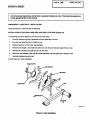 3
3
-
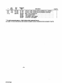 4
4
-
 5
5
-
 6
6
-
 7
7
-
 8
8
-
 9
9
-
 10
10
-
 11
11
-
 12
12
-
 13
13
-
 14
14
-
 15
15
-
 16
16
-
 17
17
-
 18
18
-
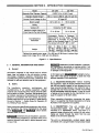 19
19
-
 20
20
-
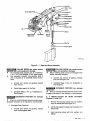 21
21
-
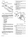 22
22
-
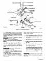 23
23
-
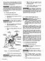 24
24
-
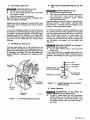 25
25
-
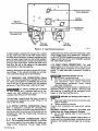 26
26
-
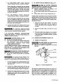 27
27
-
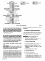 28
28
-
 29
29
-
 30
30
-
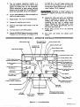 31
31
-
 32
32
-
 33
33
-
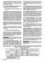 34
34
-
 35
35
-
 36
36
-
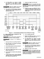 37
37
-
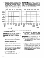 38
38
-
 39
39
-
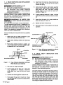 40
40
-
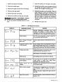 41
41
-
 42
42
-
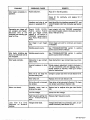 43
43
-
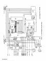 44
44
-
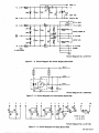 45
45
-
 46
46
-
 47
47
-
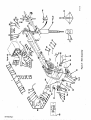 48
48
-
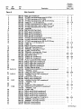 49
49
-
 50
50
-
 51
51
-
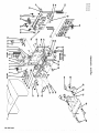 52
52
-
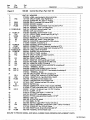 53
53
-
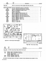 54
54
-
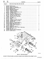 55
55
-
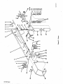 56
56
-
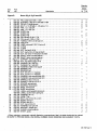 57
57
-
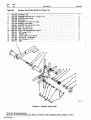 58
58
-
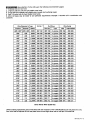 59
59
-
 60
60


Miller INTELLIMATIC DS-12M Le manuel du propriétaire
- Catégorie
- Système de soudage
- Taper
- Le manuel du propriétaire
- Ce manuel convient également à
dans d''autres langues
Documents connexes
-
Miller SWINGARC DIGITAL-1 12 AND 16 Le manuel du propriétaire
-
-
-
-
-
-
-
-