Yamaha DME24N Manuel utilisateur
- Catégorie
- Équipement musical supplémentaire
- Taper
- Manuel utilisateur
Ce manuel convient également à


The above warning is located on the top of the unit.
Explanation of Graphical Symbols
The lightning flash with arrowhead symbol
within an equilateral triangle is intended to alert
the user to the presence of uninsulated
“dangerous voltage” within the product’s
enclosure that may be of sufficient magnitude to
constitute a risk of electric shock to persons.
The exclamation point within an equilateral
triangle is intended to alert the user to the
presence of important operating and maintenance
(servicing) instructions in the literature
accompanying the product.
IMPORTANT SAFETY INSTRUCTIONS
1 Read these instructions.
2Keep these instructions.
3 Heed all warnings.
4 Follow all instructions.
5 Do not use this apparatus near water.
6 Clean only with dry cloth.
7 Do not block any ventilation openings. Install in
accordance with the manufacturer’s instructions.
8 Do not install near any heat sources such as
radiators, heat registers, stoves, or other
apparatus (including amplifiers) that produce heat.
9 Do not defeat the safety purpose of the polarized
or grounding-type plug. A polarized plug has two
blades with one wider than the other. A grounding
type plug has two blades and a third grounding
prong. The wide blade or the third prong are
provided for your safety. If the provided plug does
not fit into your outlet, consult an electrician for
replacement of the obsolete outlet.
10 Protect the power cord from being walked on or
pinched particularly at plugs, convenience
receptacles, and the point where they exit from the
apparatus.
11 Only use attachments/accessories specified by
the manufacturer.
12 Use only with the cart, stand,
tripod, bracket, or table
specified by the manufacturer,
or sold with the apparatus.
When a cart is used, use
caution when moving the cart/
apparatus combination to avoid
injury from tip-over.
13 Unplug this apparatus during lightning storms or
when unused for long periods of time.
14 Refer all servicing to qualified service personnel.
Servicing is required when the apparatus has
been damaged in any way, such as power-supply
cord or plug is damaged, liquid has been spilled or
objects have fallen into the apparatus, the
apparatus has been exposed to rain or moisture,
does not operate normally, or has been dropped.
CAUTION: TO REDUCE THE RISK OF
ELECTRIC SHOCK, DO NOT REMOVE
COVER (OR BACK). NO USER-SERVICEABLE
PARTS INSIDE. REFER SERVICING TO
QUALIFIED SERVICE PERSONNEL.
CAUTION
RISK OF ELECTRIC SHOCK
DO NOT OPEN
WARNING
TO REDUCE THE RISK OF FIRE OR ELECTRIC SHOCK,
DO NOT EXPOSE THIS APPARATUS TO RAIN OR MOISTURE.

1. IMPORTANT NOTICE: DO NOT MODIFY THIS UNIT!
This product, when installed as indicated in the instructions con-
tained in this manual, meets FCC requirements. Modifications not
expressly approved by Yamaha may void your authority, granted by
the FCC, to use the product.
2. IMPORTANT: When connecting this product to accessories and/
or another product use only high quality shielded cables. Cable/s
supplied with this product MUST be used. Follow all installation
instructions. Failure to follow instructions could void your FCC
authorization to use this product in the USA.
3. NOTE: This product has been tested and found to comply with the
requirements listed in FCC Regulations, Part 15 for Class “B” digital
devices. Compliance with these requirements provides a reason-
able level of assurance that your use of this product in a residential
environment will not result in harmful interference with other elec-
tronic devices. This equipment generates/uses radio frequencies
and, if not installed and used according to the instructions found in
the users manual, may cause interference harmful to the operation
of other electronic devices. Compliance with FCC regulations does
* This applies only to products distributed by YAMAHA CORPORATION OF AMERICA. (class B)
not guarantee that interference will not occur in all installations. If
this product is found to be the source of interference, which can be
determined by turning the unit “OFF” and “ON”, please try to elimi-
nate the problem by using one of the following measures:
Relocate either this product or the device that is being affected by
the interference.
Utilize power outlets that are on different branch (circuit breaker or
fuse) circuits or install AC line filter/s.
In the case of radio or TV interference, relocate/reorient the
antenna. If the antenna lead-in is 300 ohm ribbon lead, change the
lead-in to co-axial type cable.
If these corrective measures do not produce satisfactory results,
please contact the local retailer authorized to distribute this type of
product. If you can not locate the appropriate retailer, please con-
tact Yamaha Corporation of America, Electronic Service Division,
6600 Orangethorpe Ave, Buena Park, CA90620
The above statements apply ONLY to those products distributed by
Yamaha Corporation of America or its subsidiaries.
FCC INFORMATION (U.S.A.)
IMPORTANT NOTICE FOR THE UNITED KINGDOM
Connecting the Plug and Cord
WARNING: THIS APPARATUS MUST BE EARTHED
IMPORTANT. The wires in this mains lead are coloured in accordance
with the following code:
GREEN-AND-YELLOW : EARTH
BLUE : NEUTRAL
BROWN : LIVE
As the colours of the wires in the mains lead of this apparatus may not
correspond with the coloured markings identifying the terminals in
your plug proceed as follows:
The wire which is coloured GREEN-and-YELLOW must be connected
to the terminal in the plug which is marked by the letter E or by the
safety earth symbol or colored GREEN or GREEN-and-YELLOW.
The wire which is coloured BLUE must be connected to the terminal
which is marked with the letter N or coloured BLACK.
The wire which is coloured BROWN must be connected to the termi-
nal which is marked with the letter L or coloured RED.
• This applies only to products distributed by Yamaha-Kemble Music (U.K.) Ltd. (3 wires)
ADVARSEL!
Lithiumbatteri—Eksplosionsfare ved fejlagtig håndtering. Udskiftning
må kun ske med batteri af samme fabrikat og type. Levér det brugte
batteri tilbage til leverandoren.
VARNING
Explosionsfara vid felaktigt batteribyte. Använd samma batterityp eller
en ekvivalent typ som rekommenderas av apparattillverkaren.
Kassera använt batteri enligt fabrikantens instruktion.
VAROITUS
Paristo voi räjähtää, jos se on virheellisesti asennettu. Vaihda paristo
ainoastaan laitevalmistajan suosittelemaan tyyppiin. Hävitä käytetty
paristo valmistajan ohjeiden mukaisesti.
(lithium caution)
This product contains a battery that contains perchlorate material.
Perchlorate Material—special handling may apply,
See www.dtsc.ca.gov/hazardouswaste/perchlorate.
• This applies only to products distributed by YAMAHA CORPORATION OF AMERICA. (Perchlorate)
NEDERLAND / THE NETHERLANDS
• Dit apparaat bevat een lithium batterij voor geheugen back-up.
• This apparatus contains a lithium battery for memory back-up.
• Raadpleeg uw leverancier over de verwijdering van de batterij op het
moment dat u het apparaat ann het einde van de levensduur of
gelieve dan contact op te nemen met de vertegenwoordiging van
Yamaha in uw land.
•For the removal of the battery at the moment of the disposal at the
end of life please consult your retailer or Yamaha representative
office in your country.
• Gooi de batterij niet weg, maar lever hem in als KCA.
• Do not throw away the battery. Instead, hand it in as small chemical
waste.
(lithium disposal)

DME64N/DME24N Owner’s Manual
4
PRECAUTIONS
PLEASE READ CAREFULLY BEFORE PROCEEDING
* Please keep this manual in a safe place for future reference.
WARNING
Always follow the basic precautions listed below to avoid the possibility of serious injury or even death from
electrical shock, short-circuiting, damages, fire or other hazards. These precautions include, but are not limited
to, the following:
• Only use the voltage specified as correct for the device. The required
voltage is printed on the name plate of the device.
• Use only the specified power cord.
• Do not place the power cord near heat sources such as heaters or
radiators, and do not excessively bend or otherwise damage the cord,
place heavy objects on it, or place it in a position where anyone could walk
on, trip over, or roll anything over it.
• Be sure to connect to an appropriate outlet with a protective grounding
connection. Improper grounding can result in electrical shock.
• Do not open the device or attempt to disassemble the internal parts or
modify them in any way. The device contains no user-serviceable parts. If
it should appear to be malfunctioning, discontinue use immediately and
have it inspected by qualified Yamaha service personnel.
• Do not expose the device to rain, use it near water or in damp or wet
conditions, or place containers on it containing liquids which might spill
into any openings.
• Never insert or remove an electric plug with wet hands.
• If the power cord or plug becomes frayed or damaged, or if there is a
sudden loss of sound during use of the device, or if any unusual smells or
smoke should appear to be caused by it, immediately turn off the power
switch, disconnect the electric plug from the outlet, and have the device
inspected by qualified Yamaha service personnel.
• If this device should be dropped or damaged, immediately turn off the
power switch, disconnect the electric plug from the outlet, and have the
device inspected by qualified Yamaha service personnel.
CAUTION
Always follow the basic precautions listed below to avoid the possibility of physical injury to you or others, or
damage to the device or other property. These precautions include, but are not limited to, the following:
• Remove the electric plug from the outlet when the device is not to be used
for extended periods of time, or during electrical storms.
• When removing the electric plug from the device or an outlet, always hold
the plug itself and not the cord. Pulling by the cord can damage it.
• Before moving the device, remove all connected cables.
• When setting up the device, make sure that the AC outlet you are using is
easily accessible. If some trouble or malfunction occurs, immediately turn
off the power switch and disconnect the plug from the outlet. Even when
the power switch is turned off, electricity is still flowing to the product at
the minimum level. When you are not using the product for a long time,
make sure to unplug the power cord from the wall AC outlet.
•Avoid setting all equalizer controls and faders to their maximum.
Depending on the condition of the connected devices, doing so may cause
feedback and may damage the speakers.
• Do not expose the device to excessive dust or vibrations, or extreme cold
or heat (such as in direct sunlight, near a heater, or in a car during the day)
to prevent the possibility of panel disfiguration or damage to the internal
components.
• Do not place the device in an unstable position where it might accidentally
fall over.
Power supply/Power cord
Do not open
Water warning
If you notice any abnormality
Power supply/Power cord Location
(5)-1 1/2

DME64N/DME24N Owner’s Manual
5
• Do not block the vents. This device has ventilation holes at the front and
rear to prevent the internal temperature from rising too high. In particular,
do not place the device on its side or upside down, or place it in any
poorly-ventilated location, such as a bookcase or closet.
• Do not use the device in the vicinity of a TV, radio, stereo equipment,
mobile phone, or other electric devices. Otherwise, the device, TV, or radio
may generate noise.
• Before connecting the device to other devices, turn off the power for all
devices. Before turning the power on or off for all devices, set all volume
levels to minimum.
• Be sure to connect to a properly grounded power source. A ground screw
terminal is provided on the rear panel for safely grounding the device and
preventing electrical shock.
• Remove the power plug from the AC outlet when cleaning the device.
• Do not insert your fingers or hand in any gaps or openings on the device
(vents, ports, etc.).
• Condensation can occur in the device due to rapid, drastic changes in
ambient temperature—when the device is moved from one location to
another, or air conditioning is turned on or off, for example. Using the
device while condensation is present can cause damage. If there is reason
to believe that condensation might have occurred, leave the device for
several hours without turning on the power until the condensation has
completely dried out.
•Avoid inserting or dropping foreign objects (paper, plastic, metal, etc.)
into any gaps or openings on the device (vents, ports, etc.) If this
happens, turn off the power immediately and unplug the power cord from
the AC outlet. Then have the device inspected by qualified Yamaha service
personnel.
• Do not use the device or headphones for a long period of time at a high or
uncomfortable volume level, since this can cause permanent hearing loss.
If you experience any hearing loss or ringing in the ears, consult a
physician.
• Do not rest your weight on the device or place heavy objects on it, and
avoid use excessive force on the buttons, switches or connectors.
This device has a built-in backup battery that maintains data in internal
memory even when the device’s power is switched off. The backup battery
will eventually become depleted, however, and when that happens the
contents of the internal memory will be lost.* To prevent loss of data be sure
to replace the backup battery before it becomes fully depleted. When the
remaining capacity of the backup battery becomes so low that it needs to be
replaced a “Low Battery” or “No Battery” message will appear on the display
during operation or when the device is powered on. If either of these
messages appears do not turn off the power and immediately transfer any
data you want to save to a computer or other external storage device, then
have qualified Yamaha service personnel replace the backup battery. The
average life of the internal backup battery is approximately 5 years,
depending on operating conditions.
* Data items maintained in the internal memory by the backup battery are as
follows:
• Current scene parameters and number.
• Device parameters (SLOT, HA, UTILITY, Master Mute/Level, etc.).
• Event log.
Data items other than those described above are stored in memory that does
not require backup power, and will be retained even if the backup battery
fails.
Do not turn the [POWER] switch on and off repeatedly and rapidly. Be sure to wait six seconds or more between turning the power to the unit off and then on.
Always turn the power off when the device is not in use.
The performance of components with moving contacts, such as switches, volume controls, and connectors, deteriorates over time. Consult qualified Yamaha service
personnel about replacing defective components.
Connections
Maintenance
Handling caution
Backup battery
Yamaha cannot be held responsible for damage caused by improper use or modifications to the device, or data that is lost or destroyed.
• The illustrations in this document are for instructional purposes, and may appear somewhat different from the actual equipment.
• The bitmap fonts used in this device have been provided by and are the property of Ricoh Co., Ltd.
• CobraNet and Peak Audio are trademarks of Cirrus Logic, Inc.
• Ethernet is a trademark of Xerox Corporation.
• All other trademarks are the property of their respective holders and are hereby acknowledged.
(5)-1 2/2

Foreword
DME64N/DME24N Owner’s Manual
6
Foreword
Thank you for choosing a Yamaha DME64N/24N Digital Mixing Engine.
Using the supplied DME Designer software, the DME64N and DME24N can be easily configured to handle
a wide range of audio processing applications – institutional audio installations, sub-mixing, speaker system
control, matrix and routing, multi-effect processing, and much more.
In order to take full advantage of the features and performance provided by the DME64N/24N, we urge you
to read this owner’s manual thoroughly before use, and keep it in a safe place for future reference.
The Yamaha Pro Audio web site is at: http://www.yamahaproaudio.com/

DME64N/DME24N Owner’s Manual
7
Foreword 8
Accessories (Please make sure the following items
are included in the package.) . . . . . . . . . . . . . . . 8
Options . . . . . . . . . . . . . . . . . . . . . . . . . . . . . . . 8
About the Product Names . . . . . . . . . . . . . . . . . 8
About the Firmware Version . . . . . . . . . . . . . . . 8
Preparation . . . . . . . . . . . . . . . . . . . . . . . . . . . . 8
Connecting the AC power cord . . . . . . . . . . . . . . . . . . . .8
Turning the power on and off. . . . . . . . . . . . . . . . . . . . . .8
Introduction to the DME64N/24N 9
Differences between DME64N/24N . . . . . . . . . 9
DME64N/24N Features . . . . . . . . . . . . . . . . . . 9
Audio System Network . . . . . . . . . . . . . . . . . . . 9
Glossary for the DME64N/24N . . . . . . . . . . . . 9
Signal Types . . . . . . . . . . . . . . . . . . . . . . . . . . 11
System Examples . . . . . . . . . . . . . . . . . . . . . . . 12
About DME Designer . . . . . . . . . . . . . . . . . . . 13
The Controls and Connectors 14
Front Panel . . . . . . . . . . . . . . . . . . . . . . . . . . . 14
Rear Panel . . . . . . . . . . . . . . . . . . . . . . . . . . . . 16
Setup 18
Setup Procedure. . . . . . . . . . . . . . . . . . . . . . . . 18
I/O Card Installation. . . . . . . . . . . . . . . . . . . . 20
Compatible I/O Cards . . . . . . . . . . . . . . . . . . . . . . . . . .20
I/O Card Installation Procedure . . . . . . . . . . . . . . . . . . .21
Connecting to a Computer 22
USB Connection . . . . . . . . . . . . . . . . . . . . . . . 22
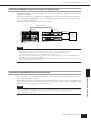
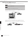
Ethernet Connection ([NETWORK] Connector) . . .23
Audio I/O Connection 26
Analog Audio Connection ([IN] and [OUT] Connectors)
(DME24N only). . . . . . . . . . . . . . . . . . . . . . . . . . . . . . .26
I/O Slots. . . . . . . . . . . . . . . . . . . . . . . . . . . . . . . . . . . . .27
Connecting to an External Device 28
Remote Connection ([REMOTE] Connector). 28
Controlling external head amplifiers from the DME64N/24N .28
Controlling a DME24N’s internal head amps from a digital mixer . 29
Controlling the DME64N/24N from an external device .29
MIDI Connection ([MIDI] Connectors) . . . . . 30
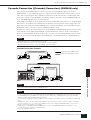
Cascade Connection ([Cascade] Connectors)
(DME64N only) . . . . . . . . . . . . . . . . . . . . . . . 31
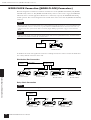
WORD CLOCK Connection ([WORD CLOCK]
Connectors) . . . . . . . . . . . . . . . . . . . . . . . . . . . 32
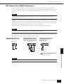
GPI Connection ([GPI] Connectors). . . . . . . . 33
Panel Operation and Displays 34
Basic Operation . . . . . . . . . . . . . . . . . . . . . . . . 34
Main Display . . . . . . . . . . . . . . . . . . . . . . . . . . 35
Parameter Edit Displays. . . . . . . . . . . . . . . . . . 36
Editing User Defined Button . . . . . . . . . . . . . . . . . . . . .38
Mute Switching . . . . . . . . . . . . . . . . . . . . . . . . . . . . . . .39
Output Level Control . . . . . . . . . . . . . . . . . . . . . . . . . . .39
Scene Recall . . . . . . . . . . . . . . . . . . . . . . . . . . . . . . . . . .39
Scene Store . . . . . . . . . . . . . . . . . . . . . . . . . . . . . . . . . . .40
Monitoring . . . . . . . . . . . . . . . . . . . . . . . . . . . . . . . . . . .40
Spectrum Display. . . . . . . . . . . . . . . . . . . . . . . 41
Level Meter Display. . . . . . . . . . . . . . . . . . . . . 42
Initializing the DME64N/DME24N . . . . . . . . 43
Utility Displays . . . . . . . . . . . . . . . . . . . . . . . . 44
Items accessible via the Utility display. . . . . . . . . . . . . . .44
Utility Display Operation . . . . . . . . . . . . . . . . . . . . . . . .46
Info Page. . . . . . . . . . . . . . . . . . . . . . . . . . . . . . . . . . . . .46
Network Settings (Net) Page. . . . . . . . . . . . . . . . . . . . . .47
Display Setup (Disp) Page . . . . . . . . . . . . . . . . . . . . . . .47
Security Setup (Lock) Page . . . . . . . . . . . . . . . . . . . . . . .48
Miscellaneous Setup (Misc) Page . . . . . . . . . . . . . . . . . .49
Word Clock Setup (WCLK) Page. . . . . . . . . . . . . . . . . .50
Slot Information (Slot) Page . . . . . . . . . . . . . . . . . . . . . .51
MIDI Setup (MIDI) Page. . . . . . . . . . . . . . . . . . . . . . . .51
GPI Setup (GPI) Page. . . . . . . . . . . . . . . . . . . . . . . . . . .53
Head Amplifier Setup (HA) Page . . . . . . . . . . . . . . . . . .54
Cascade Setup (CASCAD) Page . . . . . . . . . . . . . . . . . . .55
Check Page . . . . . . . . . . . . . . . . . . . . . . . . . . . . . . . . . . .56
References 57
Options . . . . . . . . . . . . . . . . . . . . . . . . . . . . . . 57
ICP1. . . . . . . . . . . . . . . . . . . . . . . . . . . . . . . . . . . . . . . .57
CP4SW, CP4SF, and CP1SF . . . . . . . . . . . . . . . . . . . . .57
Error Messages. . . . . . . . . . . . . . . . . . . . . . . . . 58
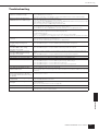
Troubleshooting . . . . . . . . . . . . . . . . . . . . . . . 61
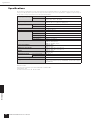
Specifications . . . . . . . . . . . . . . . . . . . . . . . . . . 62
Input/Output Characteristics. . . . . . . . . . . . . . 63
Control I/O . . . . . . . . . . . . . . . . . . . . . . . . . . . 63
Connector Pin Assign . . . . . . . . . . . . . . . . . . . 65
Dimensions . . . . . . . . . . . . . . . . . . . . . . . . . . . 67
MIDI Data Format . . . . . . . . . . . . . . . . . . . . . 68
Glossary . . . . . . . . . . . . . . . . . . . . . . . . . . . . . . 73
Index 75
Contents
Foreword
Introduction to
the DME64N/24N
The Controls
and Connectors
Preparation
Audio I/O
Connection
Connecting to
a Computer
Connecting to an
External Device
Panel Operation
and Displays
References

Foreword
Accessories (Please make sure the following items are included in the package.)
DME64N/DME24N Owner’s Manual
8
Thank you for choosing a Yamaha DME64N/24N Digital Mixing Engine.
In order to take full advantage of the features and performance provided by the DME64N/24N, we urge you to read this
owner’s manual thoroughly before connecting or using the unit. Keep this manual in a safe place for future reference.
Accessories (Please make
sure the following items are
included in the package.)
• DME64N/DM24N Owner’s Manual
(This document)
•AC power cord
•AC plug clamp
•Euroblock plug (16P) x 2
•Euroblock plug (8P) x 4 (DME64N only)
•Euroblock plug (3P) x 16 (DME24N only)
Options
Control Panels
• ICP1 Intelligent Control Panel
• CP4SW Control Panel
• CP4SF Control Panel
• CP1SF Control Panel
About the Product Names
In this manual, models DME64N, DME24N, DME8i-C,
DME8o-C, DME4io-C, DME8i-ES, DME8o-ES and
DME4io-ES are categorized as DME series, and models
DME8i-C, DME8o-C, DME4io-C, DME8i-ES,
DME8o-ES and DME4io-ES are all called the “DME
Satellite”.
About the Firmware Version
You can download the latest firmware from the following
Yamaha website.
http://www.yamahaproaudio.com/downloads/
Preparation
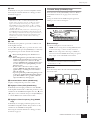
Connecting the AC power cord
First plug the female-connector end of the AC cord into
the [AC IN] socket on the rear panel of the DME64N/
24N, then plug the male plug into an appropriate AC
mains outlet.
Be sure to use the voltage specified for the device.
Turning the power on and off
1. Press the [POWER] switch to turn on the
power to the DME64N/24N.
2. Press the [POWER] switch again to turn off
the power.
Foreword
NOTE
For more information on your Control Panel, refer to the
owner’s manual that came with the Control Panel, as well as the
DME Designer Owner’s Manual.
Be sure to turn all devices OFF before connecting AC
mains power.
To prevent the initial power-on surge from generating a
large noise spike or damaging your speaker system, turn
the devices on in the following order: audio sources,
mixer (such as M7CL or PM5D), DME64N/24N, and
finally power amplifiers.
Reverse this order when turning power off.
NOTE
The DME64N/24N remembers scene settings when you turn
off the power.
When you turn on the power to the DME64N/24N, it will
start up with the same scene settings.
You can set up the DME64N/24N so that at the startup it will
recall the scene selected before you turned off the power to the
device. (page 49)
Do NOT turn off the power to the DME64N/24N
while it is receiving data from DME Designer or while it
is being manipulated from an external device. Otherwise,
a malfunction may occur.
Even when the power switch is turned off, electricity is
still flowing to the product all the minimum level.When
you are not using the product for a long time, make sure
to unplug the power cord from the wall AC outlet.
CAUTION
CAUTION
CAUTION
CAUTION

Introduction to the DME64N/24N
Differences between DME64N/24N
DME64N/DME24N Owner’s Manual
9
Differences between DME64N/24N
The DME64N has four I/O card slots, while the DME24N has one I/O card slot and eight channels of built-
in analog audio I/O.
A single I/O card can handle up to 16 channels of audio I/O, so the DME64N can handle a maximum of 64
audio I/O channels. The DME24N can handle up to 24 audio I/O channels.
The DME64N has approximately double the DSP processing power of the DME24N.
DME64N/24N Features
In addition to basic mixing and matrix output functions, the DME64N/24N includes a equalizers, compressors,
delay, etc. – that can be patched together via DME Designer to configure just about any audio system you need.
Audio System Network
Multiple DME series units that are interconnected in a network via Ethernet function as a single audio system.
In a DME audio system, a group of the same models that can be operated in sync is called a “device group;”
audio processing divisions that accommodate multiple device groups are called “zones;” and the entire area ser-
viced by the acoustic system is called an “area.”
Each device group always includes one DME series unit that functions as the “group master” and controls all
other DME series units in the same device group.
If a computer is connected to the network, you can use the computer to control an entire device group via the
group master.
Glossary for the DME64N/24N
This section explains terminology specific to the DME64N/24N.
Components and parameters
The individual audio processing modules (equalizers, compressors, etc.) are called “components.”
External head amplifier control modules are also available as components.
Changing the parameters of components enables control over the operation of the components.
Configuration
A “configuration” is a complete set of components for constructing an audio system.
Each configuration determines the audio function(s) of the corresponding DME64N/24N unit.
All parameter sets included with each component in a configuration are called “preset parameters.”
One DME64N/24N unit has a number of configurations, and a configuration has a number of preset parame-
ters.
User Defined buttons
Assigning parameters to be User Defined Buttons enables you to control the device from the ICP1 and the
DME64N/DME24N.
Refer to the DME Designer Owner’s Manual for details.
Introduction to the DME64N/24N

Introduction to the DME64N/24N
Glossary for the DME64N/24N
DME64N/DME24N Owner’s Manual
10
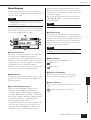
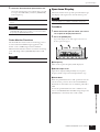
Scene
A combination of all configuration and preset parameters is called a “scene.”
Scenes can be recalled from an ICP1, GPI device, other external controllers, DME64N/DME24N, or comput-
er.
Up to 999 scenes can be stored for each device group.
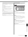
Scene structure
Scene change
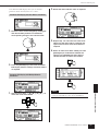
16 x 8
Scene
Scene 1
Scene 2
Scene 999
Component
Configuration
Preset
Parameter
Ex.: Gate
• Attack
• Decay
• Range
• Threshold
• Key in
• Hold
Matrix Mixer
96kHz
88.2kHz
48kHz
44.1kHz
EXT.
CLOCK
MID
MASTER
NETWORK
PEAK
SIGNAL
PEAK
SIGNAL
IN
OUT
SCENE NUMBER
12345 678
12345 678
96kHz
88.2kHz
48kHz
44.1kHz
EXT.
CLOCK
MID
MASTER
NETWORK
PEAK
SIGNAL
PEAK
SIGNAL
IN
OUT
SCENE NUMBER
12345 678
12345 678
First Act Dark Change Second Act
Band Set
Play Set
Stage Stage Stage
Play
Set
Band
Set
Band Set
Play Set
Scene 1 Scene Recall Scene 2

Introduction to the DME64N/24N
Signal Types
DME64N/DME24N Owner’s Manual
11
Signal Types
DME64N/24N audio system signals can be broadly categorized as follows.
1 Audio
The DME64N/24N will be required to send and receive audio signals to and from other DME series units as
well as other audio equipment.
Audio signal transmission and reception will occur primarily via the [INPUT] and [OUTPUT] connectors on
the DME24N.
2 Control signals within a device group
Device group control signals control all DME series devices in the group.
There are two types of device group control signals, as follows:
• Control signals between the computer and the group master DME series unit
• Control signals between the group master DME series unit and the other DME series
units
You can use the DME Designer application to control the entire device group, such as sending components to
the devices and setting the parameters as required.
3 Control signals between devices outside the device group
These signals provide communication and control between individual devices.
Included in this category are MIDI messages transferred between [USB] connectors, GPI signals transferred be-
tween [GPI] connectors, and remote head amp control signals handled via the [REMOTE] connector.
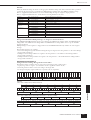
Type of signals handled by the DME64N/24N
Connector Audio Signal Device Control Word Clock
Reference
Page
[USB]
Connector
–•Control signals between computer and
DNE64N/24N
• MIDI messages
–22
[NETWORK]
Connector
–•Control signals between computer and
DNE64N/24N
• Control signals between DME series
unit.
–23
[MIDI]
Connector
– Control signals (MIDI commands)
between MIDI controller and DME64N/
24N.
–30
[GPI]
Connector
– Control signals between GPI device (GPI
controller, etc.) and DME series unit
–33
[CASCADE]
Connector
(DME64N
only)
32 channels of
input/output.
Control signals from the digital mixer to
the DME64N
Word clock transmission and
reception to and from other
devices.
31
[WORD
CLOCK]
Connector
––Word clock transmission and
reception to and from other
devices.
32
[REMOTE]
Connector
–•Control signals to/from an external
device (such as AD8HR head amplifier)
• Control signals for a digital mixer and
internal head amp
• Control signals with a controller such as
an AMX or Crestron
• MIDI messages
–28
(Audio I/O
Connectors)
(DME24N
only)
8 channels of
input and output.
––26
(I/O Slot) Number of I/O
channels depends
on card.
Serial signal transmission/reception
(depending on function of card).
Word clock transmission and
reception to and from other
devices (depending on function
of card).
27

Introduction to the DME64N/24N
System Examples
DME64N/DME24N Owner’s Manual
12
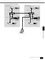
System Examples
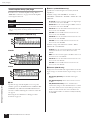
Large systems using CobraNet
HOMEHOME UTILITYUTILITYSCENESCENE LEVELLEVEL MUTEMUTE
ENTERENTERCANCELCANCEL
USB
PEAK
PEAK
SIGNAL
SIGNAL
PEAK
PEAK
SIGNAL
SIGNAL
PEAK
PEAK
SIGNAL
SIGNAL
INPUT
INPUT
DIGITAL MIXING ENGINE SATELLITE
USB
PEAK
PEAK
SIGNAL
SIGNAL
PEAK
PEAK
SIGNAL
SIGNAL
PEAK
PEAK
SIGNAL
SIGNAL
INPUT
INPUT
DIGITAL MIXING ENGINE SATELLITE
USB
PEAK
PEAK
SIGNAL
SIGNAL
PEAK
PEAK
SIGNAL
SIGNAL
PEAK
PEAK
SIGNAL
SIGNAL
INPUT
INPUT
DIGITAL MIXING ENGINE SATELLITE
USB
PEAK
PEAK
SIGNAL
SIGNAL
PEAK
PEAK
SIGNAL
SIGNAL
PEAK
PEAK
SIGNAL
SIGNAL
INPUT
INPUT
DIGITAL MIXING ENGINE SATELLITE
96kHz
88.2kHz
48kHz
44.1kHz
EXT.
CLOCK
MID
MASTER
NETWORK
PEAK
SIGNAL
PEAK
SIGNAL
IN
OUT
SCENE NUMBER
12345 678
12345 678
96kHz
88.2kHz
48kHz
44.1kHz
EXT.
CLOCK
MID
MASTER
NETWORK
PEAK
SIGNAL
PEAK
SIGNAL
IN
OUT
SCENE NUMBER
12345 678
12345 678
DME8o-C
DME8o-C
DME8o-C
DME8o-C
DME8i-C
DME8i-C
DME8i-C
DME8i-C
DME24N
DME64N
DME24N
MY16-CII
MY16-CII
MY16-CII x 4
ICP1
Computer
Hub
Hub
Hub
Hub
Hub
Hub
Hub
Hub
Space BSpace A
Space C
Space D
Analog In
Analog In
Analog In
Analog In
Analog Out
Analog Out
Analog Out
Analog Out
Analog In
Analog In
Analog Out
Ethernet
CobraNet
Ethernet Switching Hub
CobraNet Switching Hub
Analog Out

Introduction to the DME64N/24N
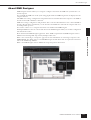
About DME Designer
DME64N/DME24N Owner’s Manual
13
About DME Designer
DME Designer software enables you to integrate, configure, and control the DME series system from a con-
nected computer.
You can build the DME series audio system using graphic blocks in DME Designer that are displayed on the
computer monitor.
The DME series settings, configuration, and parameter data are transferred from the computer to the DME se-
ries unit via the USB or Ethernet connection.
DME series settings, configuration, and parameter data is sent via USB or Ethernet to the connected DME se-
ries unit. After the data is transmitted, you can disconnect the DME series unit from the computer and use it
as an independent processor.
You can also connect it to a computer and control it in realtime from DME Designer.
If multiple DME series units are connected in the network, DME Designer enables you to build a configuration
that includes those units.
Please download the DME Designer application, driver, DME setup manual, and DME Designer Owner’s
Manual at the following URL: http://www.yamahaproaudio.com/
Refer to the “Connecting to a Computer” (page 22) for more information on connecting a computer to the
DME64N/24N. For details on how to install DME Designer and the drivers that are required for connection,
refer to the “DME Setup Manual.”
Refer to the DME Designer Owner’s Manual for setup and operation instructions.

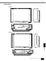
The Controls and Connectors
Front Panel
DME64N/DME24N Owner’s Manual
14
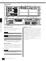
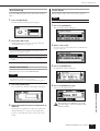
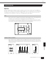
Front Panel
1 [USB] Connector
A computer can be connected here when it is necessary to
program or control the device. When a USB connection is
to be used, the USB-MIDI driver must be installed on the
computer. Refer to the DME Designer Installation Guide
for installation instructions.
2 [EXT. CLOCK] Indicator
When a clock signal from an external device is selected, the
indicator will light green. If the clock signal is not
appropriate the indicator will flash red. The indicator will
go out when the internal word clock is selected.
3 [96kHz] [88.2kHz] [48kHz] [44.1kHz]
Indicator
Normally, the indicator corresponding to the current word
clock frequency will light green. If a problem with the
master clock is detected all of these indicators will flash red.
2 seconds after a problem is detected with an external
master clock the internal clock will temporarily be selected.
When this happens the indicator corresponding to the
frequency of the internal clock will light green, and all
other indicators will continue to flash red.
4 [NETWORK] Indicator
Lights while data communication is occurring via the
[USB], [NETWORK], or [CASCADE] connector.
Received data causes the indicator to light in green, while
transmitted data causes the indicator to light in orange. If a
problem occurs the indicator will light in red.
The Controls and Connectors
HOMEHOME UTILITYUTILITYSCENESCENE LEVELLEVEL MUTEMUTE
ENTERENTERCANCELCANCEL
HOMEHOME UTILITYUTILITYSCENE LEVELLEVEL MUTEMUTE
ENTERENTERCANCELCANCEL
1
1
2
4
5
6
7
8
7
8
9
9
)
)
^
&
^
&
º
¡
™
£
º
¡
™
£
*(
*(
! @#$%
! @#$%
2
4
5
6
3
3
DME64N
DME24N

The Controls and Connectors
Front Panel
DME64N/DME24N Owner’s Manual
15
5 [MIDI] Indicator
Lights while data communication is occurring via the
[MIDI] connector. Received data causes the indicator to
light green, while transmitted data causes the indicator to
light orange. The indicator will light green when reception
and transmission occur simultaneously. If a problem occurs
the indicator will light red.
6 [MASTER] Indicator
Lights green when the device is operating as the device
group master (page 9). The indicator will not light if the
device is operating as a device group slave. Refer to page 46
for device group master setup instructions.
7 [PEAK] Indicator (DME24N only)
Light red when a signal on the corresponding built-in
analog audio input or output ([IN] and [OUT]
connectors) reaches or exceeds -3 dB.
8 [SIGNAL] Indicator (DME24N only)
Light green when a signal with a level greater than -40 dB
is present at the built-in analog audio inputs and outputs
([IN] and [OUT] connectors).
9 [SCENE NUMBER] Indicator
Shows the current scene number.
) Display
Displays scene information and device parameters.
! [SCENE] Button
Calls the scene recall/store display (page 39). The scene
store display will appear if the button is held for longer
than 2 seconds (page 40). The indicator will light green
while the scene recall or store display is showing.
@ [HOME] Button
Directly recalls the home (main) display. If pressed while
the main display is showing the [HOME] button steps
through the user-defined parameter display pages (refer to
page 38 in this manual).
# [UTILITY] Button
Calls the output level display. If this button is held for
longer than 2 seconds while the main display is showing
the utility display will appear. Switches between the Utility
display pages if pressed while the Utility display is showing.
$ [LEVEL] Button
Calls the output level setup display (page 39).
The indicator will light green.
% [MUTE] Button
Calls the mute display (page 39). The indicator will light
orange when mute is on. The indicator will light green
when mute is off and the mute display is showing, and will
be off if the mute display is not showing.
^ Dial
Adjusts the value of selected parameters.
& [E] [ ▲ ] [ ▼ ] [F] Buttons
Move the display cursor in the corresponding directions.
* [CANCEL] Button
Closes the window on the display.
( [ENTER] Button
Confirms and enters a value or setting.
º [PHONES] Jack
A pair of headphones can be plugged in here.
¡ [PHONES LEVEL] Control
Adjusts the headphone volume. Even when the control is
set to the minimum level, the sound at the headphones is
not completely muted.
™ [MONITOR] Button
Calls the monitoring point slot selection display (page 40).
When the [ENTER] button is pressed to select a slot, the
monitoring point selection display will appear.
The spectrum analyzer display will then appear when the
[ENTER] button is pressed to select a monitoring point.
The indicator will light green while the monitoring slot/
point or spectrum analyzer display is showing.
£ [POWER] Switch
Turns mains power to the device on and off.
NOTE
The DME64N has no built-in analog audio inputs or outputs
([IN] and [OUT] connectors).
Even when the power switch is turned off, electricity is
still flowing to the product all the minimum level.
When you are not using the product for a long time,
make sure to unplug the power cord from the wall AC
outlet.
CAUTION

The Controls and Connectors
Rear Panel
DME64N/DME24N Owner’s Manual
16
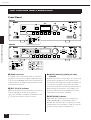
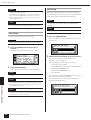
Rear Panel
1 [AC IN] Connector
This is the device’s three-pronged AC power connector.
Connect to the AC mains using the supplied AC power
cord. See “Setup” on page 18 for details.
Even when the power switch is turned off, electricity is
still flowing to the product all the minimum level. When
you are not using the product for a long time, make sure
to unplug the power cord from the wall AC outlet.
2 Ground Screw
The supplied AC power cable is a 3-wire type, so if the AC
outlet used is properly earthed the DME64N/24N will be
earthed as well. Hum and interference may by further
reduced in some cases by also connecting the earth screw
to an earth point.
3 [GPI] Connector
This Euroblock connector provides access to the unit’s GPI
(General Purpose Interface) interface for transfer of control
signals to and from external equipment. The DME64N
provides 16 channels of GPI input and output, while the
DME24N provides 8 channels. Each input channel has an
IN terminal and a +V terminal. Output channels each have
an OUT terminal and a GND terminal. The open voltage
at the +V terminal is 5V, while the IN terminal detects
voltage changes from 0V ~ 5V. The OUT terminals output
either signal “L” or “H” at a TTL level.
See “GPI Connection ([GPI] Connectors)” on page 33 for
connection details.
3
8
32
21
)6574
1
9
5674
9
DME64N
DME24N
NOTE
Use the supplied AC cord clamp to prevent accidental
disconnection of the AC power.
NOTE
When connecting to two-prong type AC mains outlets use the
supplied plug adaptor.
NOTE
Connect the device to only one ground point.
Connecting the device to more than ground point can result in
ground loops that can cause increased hum and noise.
CAUTION

The Controls and Connectors
Rear Panel
DME64N/DME24N Owner’s Manual
17
4 [MIDI IN] [MIDI OUT] [MIDI THRU]
Connectors
These are standard MIDI connectors that handle reception
and transmission of MIDI data: [MIDI IN] receives MIDI
data, [MIDI OUT] transmits MIDI data, and [MIDI
THRU] re-transmits MIDI data received at the [MIDI
IN] connector. See “MIDI Connection ([MIDI]
Connectors)” on page 30 for connection details.
5 [WORD CLOCK IN] [WORD CLOCK OUT]
Connectors
These BNC connector receive and transmit word clock
from and to external equipment. See “WORD CLOCK
Connection ([WORD CLOCK] Connectors)” on page 32
for connection details. Word clock settings are available via
the device’s Utility display WCLK page (see page 50 of this
document).
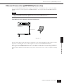
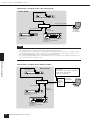
6 [NETWORK] Connector
This is a 100Base-TX/10Base-T Ethernet connector for
connection to a computer or other DME series units.
Normally this connector will be connected to a network
hub via an Ethernet “straight” cable. When two
DME64N/24N units are to be directly connected a “cross”
cable should be used. See “Ethernet Connection
([NETWORK] Connector)” on page 23 for connection
details.
7 [REMOTE] Connector
This 9-pin D-SUB connector allows connection to
Yamaha AD824 or AD8HR remote head amplifier or an
RS-232C/RS-422 compatible controller such as those
from AMX or Crestron. You can also connect a Yamaha
PM5D or DM2000 and control the internal head amps of
DME24N. Refer to page 28 for connection details.
8
[IN] [OUT] Connectors (DME24N only)
These are balanced Euroblock connectors for analog audio
input and output. The analog signal from microphones or
line sources such as CD players can be input via the IN
connectors, while the OUT connectors can deliver analog
output to powered speakers or recording equipment. 48V
phantom power can be supplied to the IN connectors
(page 53). Refer to page 26 for [IN] and [OUT]
connection details.
9 I/O Slots
Optional Yamaha or third-party mini-YGDAI cards can be
plugged in here for system expansion. The DME64N has
four I/O slots, while the DME24N has one.
One expansion card can be plugged into each slot. Refer to
“I/O Card Installation” on page 20 for installation details.
) [CASCADE IN] [CASCADE OUT]
Connectors (DME64N only)
This 68-pin D-SUB connector can be connected to the
CASCADE connector of other devices via a dedicated
cascade cable. The CASCADE connector transmits and
receives control, audio, and word clock signals. Refer to
“Cascade Connection ([Cascade] Connectors” on page 31
for connection details.
NOTE
Use a STP (Shielded Twisted Pair) cable for this connection to
prevent electromagnetic interference.
NOTE
The [IN] and [OUT] connectors each have 24 terminal pins.
Each of the eight inputs and outputs uses three pins – hot, cold,
and ground. Use the supplied 3-pin Euroblock plugs to connect
to the appropriate inputs and outputs.

Preparation
Setup Procedure
DME64N/DME24N Owner’s Manual
18
Setup Procedure
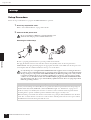
Follow the steps outlined below to prepare the DME64N/24N for operation.
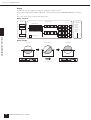
1. Install any required I/O cards.
Refer to “I/O Card Installation” on page 20 for details.
2. Connect the AC power cord.
Be sure to turn all devices OFF before connecting AC mains power.
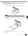
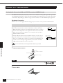
Attach the cable clamp to prevent accidental disconnection.
Attaching the cable clamp.
Be sure to properly ground the device to prevent possible electrical shock.
First plug the female-connector end of the AC cord into the [AC IN] socket on the rear panel of the
DME64N/24N, then plug the male plug into an appropriate AC mains outlet. Make sure the AC power to be
used complies with the conditions marked on the top cover of the device.
Use only the AC power cord supplied with the DME64N/24N. If the supplied cord is lost or damaged and needs to
be replaced, contact your Yamaha dealer. The use of an inappropriate replacement can pose a fire and shock hazard!
The type of AC power cord provided with the DME64N/24N may be different depending on the country in which
it is purchased (a third prong may be provided for grounding purposes). Improper connection of the grounding
conductor can create the risk of electrical shock. Do NOT modify the plug provided with the DME64N/24N. If the
plug will not fit the outlet, have a proper outlet installed by a qualified electrician. Do not use a plug adapter which
defeats the grounding conductor.
Setup
Security Cover Mounting
Security cover mounting screw holes (M3 size) are provided on the front panel of the unit. The spacings are
423mm width and 96mm (DME64N) / 52mm (DME24N) height. See “Dimensions” on page 67 for
details. A security cover made by the customer or contractor can be attached to the front panel via these
mounting holes to prevent accidental operation. Yamaha cannot supply a security cover.
When mounting a cover make sure that the screws used do not go deeper than 15 millimeters into the front
panel. Also, to ensure that the cover does not come in contact with the panel controls, leave a space of about
20 millimeters between the front panel and the cover.
CAUTION
WARNING

Preparation
Setup Procedure
DME64N/DME24N Owner’s Manual
19
3. Install the DME Designer software and necessary drivers on the computer to be used for
device group control.
See the “DME Setup Manual” (PDF file) for details.
4. Connect devices.
•Network connection
Ethernet connection (page 23)
USB connection (page 22)
• Analog connection (page 26)
•External device connection
Remote connection (page 28)
MIDI connection(page 30)
CASCADE connection(page 31)
WORD CLOCK connection(page 32)
GPI connection (page 33)
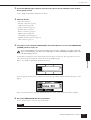
5. Turn power to the computer, DME64N/24N, and related devices on. Press the DME64N/24N
[POWER] switch to turn it on.
To prevent the initial power-on surge from generating a large noise spike or damaging your speaker system, turn
devices on in the following order: audio sources, mixer and/or recorders, and finally power amplifiers. Reverse this
order when turning power off.
No information will appear on the display the first time the device is turned on. The appropriate scene and
other data must first be transferred to the device from the DME Designer.
Refer to the “DME Setup Manual” (PDF file) for details.
Once the appropriate data has been transferred to the device, the current number and name will appear on the
display:
If any scene data has been stored in the DME64N/24N, the current scene and its name will be displayed.
6. Set up the DME64N/24N operation parameters.
See the “Utility Display” section on page 44 for details.
NOTE
The “NET” page settings must be set up as required before using the unit for the first time.
CAUTION

Preparation
I/O Card Installation
DME64N/DME24N Owner’s Manual
20
7. Launch the DME Designer application, create configuration and transfer.
DME Designer setup, operation, and data transfer instructions can be found in the DME Designer Manual.
This completes preparation of the DME64N/24N system.
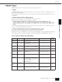
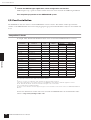
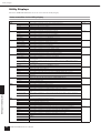
I/O Card Installation
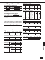
The DME64N has four I/O card slots, and the DME24N has one I/O card slot. The number of audio input channels
available on the DME64N/24N can be increased by plugging the appropriate mini-YGDAI I/O card(s) into the available card
slot(s).
Compatible I/O Cards
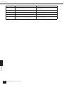
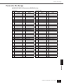
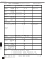
As of April, 2007, Yamaha mini-YGDAI cards that can be used with the DME64N/24N are as follows:
The input/output numbers above apply to 44.1/48kHz operation.
(*)
In order to use three or four MY16-C cards, firmware V1.10 or later will be required.
If the serial number written on the upper surface of your DME64N is shown below, a hardware upgrade is needed.
KK, KL, KM, KN, KO, KP, KX, KY are the third and fourth digits of the serial number.
A fee is charged for the hardware upgrade.
For details, contact Yamaha customer support using the contact information located at the end of the “DME64N/24N Owner’s
Manual.”
For the latest information on what cards can be used with the DME64N/24N, visit the Yamaha Pro Audio
website at: http://www.yamahaproaudio.com/
Card Name Function Input Output
No. of Available Cards
DME64N DME24N
MY8-AT ADAT 8 8 4 1
MY8-TD TDIF-1 8 8 4 1
MY8-AE AES/EBU 8 8 4 1
MY4-AD ANALOG IN 4 – 4 1
MY8-AD ANALOG IN 8 – 4 1
MY4-DA ANALOG OUT – 4 4 1
MY8-AD24 ANALOG IN 8 – 4 1
MY8-AD96 ANALOG IN 8 – 4 1
MY8-DA96 ANALOG OUT – 8 4 1
MY8-ADDA96 ANALOG IN/OUT 8 8 4 1
MY8-AE96S AES/EBU 8 8 4 1
MY8-AE96 AES/EBU 8 8 4 1
MY8-AEB AES/EBU 8 8 4 1
MY16-AT ADAT 16 16 4 1
MY16-AE AES/EBU 16 16 4 1
MY16-TD TDIF-1 16 16 4 1
MY16-C CobraNet 16 16 4(*) 1
MY16-CII CobraNet 16 16 4 1
La page charge ...
La page charge ...
La page charge ...
La page charge ...
La page charge ...
La page charge ...
La page charge ...
La page charge ...
La page charge ...
La page charge ...
La page charge ...
La page charge ...
La page charge ...
La page charge ...
La page charge ...
La page charge ...
La page charge ...
La page charge ...
La page charge ...
La page charge ...
La page charge ...
La page charge ...
La page charge ...
La page charge ...
La page charge ...
La page charge ...
La page charge ...
La page charge ...
La page charge ...
La page charge ...
La page charge ...
La page charge ...
La page charge ...
La page charge ...
La page charge ...
La page charge ...
La page charge ...
La page charge ...
La page charge ...
La page charge ...
La page charge ...
La page charge ...
La page charge ...
La page charge ...
La page charge ...
La page charge ...
La page charge ...
La page charge ...
La page charge ...
La page charge ...
La page charge ...
La page charge ...
La page charge ...
La page charge ...
La page charge ...
La page charge ...
La page charge ...
La page charge ...
La page charge ...
La page charge ...
-
 1
1
-
 2
2
-
 3
3
-
 4
4
-
 5
5
-
 6
6
-
 7
7
-
 8
8
-
 9
9
-
 10
10
-
 11
11
-
 12
12
-
 13
13
-
 14
14
-
 15
15
-
 16
16
-
 17
17
-
 18
18
-
 19
19
-
 20
20
-
 21
21
-
 22
22
-
 23
23
-
 24
24
-
 25
25
-
 26
26
-
 27
27
-
 28
28
-
 29
29
-
 30
30
-
 31
31
-
 32
32
-
 33
33
-
 34
34
-
 35
35
-
 36
36
-
 37
37
-
 38
38
-
 39
39
-
 40
40
-
 41
41
-
 42
42
-
 43
43
-
 44
44
-
 45
45
-
 46
46
-
 47
47
-
 48
48
-
 49
49
-
 50
50
-
 51
51
-
 52
52
-
 53
53
-
 54
54
-
 55
55
-
 56
56
-
 57
57
-
 58
58
-
 59
59
-
 60
60
-
 61
61
-
 62
62
-
 63
63
-
 64
64
-
 65
65
-
 66
66
-
 67
67
-
 68
68
-
 69
69
-
 70
70
-
 71
71
-
 72
72
-
 73
73
-
 74
74
-
 75
75
-
 76
76
-
 77
77
-
 78
78
-
 79
79
-
 80
80


Yamaha DME24N Manuel utilisateur
- Catégorie
- Équipement musical supplémentaire
- Taper
- Manuel utilisateur
- Ce manuel convient également à
dans d''autres langues
- italiano: Yamaha DME24N Manuale utente
- English: Yamaha DME24N User manual
- español: Yamaha DME24N Manual de usuario
- Deutsch: Yamaha DME24N Benutzerhandbuch
- русский: Yamaha DME24N Руководство пользователя
- Nederlands: Yamaha DME24N Handleiding
- português: Yamaha DME24N Manual do usuário
- dansk: Yamaha DME24N Brugermanual
- polski: Yamaha DME24N Instrukcja obsługi
- čeština: Yamaha DME24N Uživatelský manuál
- svenska: Yamaha DME24N Användarmanual
- Türkçe: Yamaha DME24N Kullanım kılavuzu
- suomi: Yamaha DME24N Ohjekirja
- română: Yamaha DME24N Manual de utilizare
Documents connexes
-
Yamaha V3 Manuel utilisateur
-
Yamaha DME64N/24N V4.0 Le manuel du propriétaire
-
-
-
-
-
-
-
-

