Skil HD5860 Manuel utilisateur
- Catégorie
- Scies circulaires
- Taper
- Manuel utilisateur
Ce manuel convient également à

IMPORTANT: IMPORTANT : IMPORTANTE:
Read Before Using Lire avant usage Leer antes de usar
Operating/Safety Instructions
Consignes de fonctionnement/sécurité
Instrucciones de funcionamiento y seguridad
HD5860
For English Version
Version française
Versión en español
See page 2 Voir page 14 Ver la página 26
1-877-SKIL999 (1-877-754-5999) www.skil.com
Call Toll Free for
Consumer Information
& Service Locations
Pour obtenir des informations
et les adresses de nos centres
de service après-vente,
appelez ce numéro gratuit
Llame gratis para
obtener información
para el consumidor y
ubicaciones de servicio
!1619X01359!
SM 1619X01359 02-06 2/16/06 1:50 PM Page 1

-2-
Read and understand all instructions. Failure to follow all instructions listed
below, may result in electric shock, fire and/or serious personal injury.
SAVE THESE INSTRUCTIONS
Work Area
Keep your work area clean and well lit.
Cluttered benches and dark areas invite
accidents.
Do not operate power tools in explosive
atmospheres, such as in the presence of
flammable liquids, gases, or dust.
Power
tools create sparks which may ignite the dust
or fumes.
Keep by-standers, children, and visitors
away while operating a power tool.
Distractions can cause you to lose control.
Electrical Safety
Grounded tools must be plugged into an
outlet properly installed and grounded in
accordance with all codes and
ordinances. Never remove the grounding
prong or modify the plug in any way. Do
not use any adaptor plugs. Check with a
qualified electrician if you are in doubt as
to whether the outlet is properly
grounded.
If the tools should electrically
malfunction or break down, grounding
provides a low resistance path to carry
electricity away from the user. Improper
grounding can shock, burn or electrocute.
Grounded tools are equipped with three
conductor cord and three prong type plugs.
Before plugging in the tool be certain the
outlet voltage supplied is within the voltage
marked on the nameplate. Do not use “AC
only” rated tools with a DC power supply.
Avoid body contact with grounded
surfaces such as pipes, radiators, ranges
and refrigerators
. There is an increased
risk of electric shock if your body is
grounded. If operating the power tool in
damp locations is unavoidable, a Ground
Fault Circuit Interrupter must be used to
supply the power to your tool. Electrician’s
rubber gloves and footwear will further
enhance your personal safety.
Don't expose power tools to rain or wet
conditions
. Water entering a power tool will
increase the risk of electric shock.
Do not abuse the cord. Never use the cord
to carry the tools or pull the plug from an
outlet. Keep cord away from heat, oil,
sharp edges or moving parts. Replace
damaged cords immediately.
Damaged
cords increase the risk of electric shock.
When operating a power tool outside, use
an outdoor extension cord marked "W-A"
or "W."
These cords are rated for outdoor
use and reduce the risk of electric shock.
Refer to “Recommended sizes of Extension
Cords” in the Accessory section of this
manual.
Personal Safety
Stay alert, watch what you are doing and
use common sense when operating a
power tool. Do not use tool while tired or
under the influence of drugs, alcohol, or
medication.
A moment of inattention while
operating power tools may result in serious
personal injury.
Dress properly. Do not wear loose
clothing or jewelry. Contain long hair.
Keep your hair, clothing, and gloves away
from moving parts.
Loose clothes, jewelry,
or long hair can be caught in moving parts.
Keep handles dry, clean and free from oil
and grease.
Avoid accidental starting. Be sure switch
is “OFF” before plugging in
. Carrying tools
with your finger on the switch or plugging in
tools that have the switch “ON” invites
accidents.
Remove adjusting keys or wrenches
before turning the tool “ON”
. A wrench or
a key that is left attached to a rotating part of
the tool may result in personal injury.
Do not overreach. Keep proper footing
and balance at all times
. Proper footing
and balance enables better control of the tool
in unexpected situations.
Use safety equipment. Always wear eye
protection
. Dust mask, non-skid safety
shoes, hard hat, or hearing protection must
be used for appropriate conditions.
!
WARNING
Power Tool Safety Rules
SM 1619X01359 02-06 2/16/06 1:50 PM Page 2

-3-
Safety Rules for Circular Saws
Tool Use and Care
Use clamps or other practical way to
secure and support the workpiece to a
stable platform.
Holding the work by hand
or against your body is unstable and may
lead to loss of control.
Do not force tool. Use the correct tool for
your application
. The correct tool will do the
job better and safer at the rate for which it is
designed.
Do not use tool if switch does
not turn it “ON” or “OFF”.
Any tool that
cannot be controlled with the switch is
dangerous and must be repaired.
Disconnect the plug from the power
source before making any adjustments,
changing accessories, or storing the tool.
Such preventive safety measures reduce the
risk of starting the tool accidentally.
Store idle tools out of reach of children
and other untrained persons.
Tools are
dangerous in the hands of untrained users.
Maintain tools with care. Keep cutting
tools sharp and clean.
Properly maintained
tools, with sharp cutting edges are less likely
to bind and are easier to control. Any
alteration or modification is a misuse and
may result in a dangerous condition.
Check for misalignment or binding of
moving parts, breakage of parts, and any
other condition that may affect the tools
operation. If damaged, have the tool
serviced before using.
Many accidents are
c
aused by poorly maintained tools. Develop
a
periodic maintenance schedule for your
tool.
Use only accessories that are
recommended by the manufacturer for
your model.
Accessories that may be
suitable for one tool, may become hazardous
when used on another tool.
Service
Tool service must be performed only by
qualified repair personnel.
Service or
maintenance performed by unqualified
personnel could result in a risk of injury. For
example: internal wires may be misplaced or
pinched, safety guard return springs may be
improperly mounted.
When servicing a tool, use only identical
replacement parts. Follow instructions in
the Maintenance section of this manual.
Use of unauthorized parts or failure to follow
Maintenance Instructions may create a risk
of electric shock or injury. Certain cleaning
agents such as gasoline, carbon
tetrachloride, ammonia, etc. may damage
plastic parts.
Keep hands away from
cutting area and blade. Keep
your second hand on auxiliary handle, or
motor housing.
If both hands are holding the
saw, they cannot be cut by the blade.
Hold the
saw firmly to prevent loss of control. Figures in
this manual illustrate typical hand support of the
saw. NEVER place your hand behind the saw
blade since kickback could cause the saw to
jump backwards over your hand.
Keep your body positioned to either side of
the saw blade, but not in line with the saw
blade.
KICKBACK could cause the saw to jump
backwards. (See “Causes and Operator
Prevention of Kickback.”)
Do not reach underneath the work. The
guard cannot protect you from the blade below
the work.
Do not attempt to remove cut material
when blade is moving.
Check lower guard for proper closing before
each use. Do not operate saw if lower guard
does not move freely and close instantly.
Never clamp or tie the lower guard into the
open position.
If saw is accidentally dropped,
lower guard may be bent. Raise the lower guard
only with the Lower Guard Lift Lever and make
sure it moves freely and does not touch the
blade or any other part, in all angles and depths
of cut.
DANGER
!
SM 1619X01359 02-06 2/16/06 1:50 PM Page 3

-4-
Check the operation of the lower guard
spring. If the guard and the spring are not
operating properly, they must be serviced
before use.
Lower guard may operate
sluggishly due to damaged parts, gummy
d
eposits, or a buildup of debris.
D
isconnect the
plug from power source. Periodically remove
the blade, clean the upper, lower guards and
the hub area with kerosene and wipe it dry, or
blow it clean with compressed air.
Lower guard should be retracted manually
only for special cuts such as “Pocket Cuts”
and “Compound Cuts”. Raise lower guard
by Lower Guard Lift Lever.
As soon as blade
enters the material, lower guard must be
released. For all other sawing, the lower guard
should operate automatically.
Always observe that the lower guard is
covering the blade before placing saw down
on bench or floor.
An unprotected, coasting
blade will cause the saw to walk backwards,
cutting whatever is in its path. Be aware of the
time it takes for the blade to stop after switch is
released.
NEVER hold piece being cut in your hands
or across your leg.
It is important to support
the work properly to minimize body exposure,
blade binding, or loss of control.
Hold tool by the insulated gripping surfaces
when performing an operation where the
cutting tool may contact hidden wiring or it
own cord.
Contact with a "live" wire will also
make exposed metal parts of the tool “live” and
shock the operator.
When ripping always use a rip fence or
straight edge guide.
This improves accuracy
of cut and reduces the chance for blade binding.
Always use blades with correct size and
shape (diamond vs. round) arbor holes.
Blades that do not match the mounting
hardware of the saw will run eccentrically,
causing loss of control and will not allow proper
vari-torque engagement.
Never use damaged or incorrect blade
washers or bolts.
The blade washers and bolt
were specially designed for your saw, for
optimum performance and safety of operation.
The blade washers and the bolt on your saw
have been designed to work as a “VARI-
TORQUE CLUTCH”. Understand the operation
and settings of the VARI-TORQUE CLUTCH,
because the proper setting of the CLUTCH,
combined with firm handling of the saw will
allow you to control KICKBACK.
Do not run the saw while carrying it at your
side. Lower guard may be opened by a
contact with your clothing.
Accidental contact
with the spinning saw blade could result in
serious personal injury.
Depending upon use, the switch may not
last the life of the saw. If the switch should
fail in the “OFF” position, the saw may not
start. If it should fail while the saw is
running, the saw may not shut off.
If either
occurs, unplug the saw immediately and do not
use until repaired.
This circular saw should not be mounted to
a table and converted to a table saw.
Circular
saws are not designed or intended to be used
as table saws.
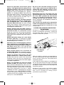
CAUSES AND OPERATOR PREVENTION
OF KICKBACK:
Kickback is a sudden reaction to a pinched,
bound or misaligned saw blade, causing an
uncontrolled saw to lift up and out of the
workpiece toward the operator.
When the blade is pinched or bound tightly by
the kerf closing down, the blade stalls and the
motor reaction drives the unit rapidly back
toward the operator.
If the blade becomes twisted or misaligned in
the cut, the teeth at the back edge of the blade
can dig into the top surface of the wood causing
the blade to climb out of the kerf and jump back
toward the operator.
Kickback is the result of tool misuse and/or
incorrect operating procedures or conditions
and can be avoided by taking proper
precautions as given below:
VARI-TORQUE
CLUTCH
SM 1619X01359 02-06 2/16/06 1:50 PM Page 4

Maintain a firm grip with both hands on the
saw and position your body and arm to
allow you to resist KICKBACK forces.
KICKBACK forces can be controlled by the
operator, if proper precautions are taken.
When blade is binding, or when interrupting
a cut for any reason, release the trigger and
hold the saw motionless in the material until
the blade comes to a complete stop. Never
attempt to remove the saw from the work or
pull the saw backward while the blade is in
motion or KICKBACK may occur.
Investigate
and take corrective action to eliminate the cause
of blade binding.
Wet lumber, green lumber or
pressure treated lumber require special
attention during cutting operation to prevent
KICKBACK. Avoid cutting nails. Inspect for and
remove all nails from lumber before cutting.
When restarting a saw in a workpiece,
center the saw blade in the kerf and check
that saw teeth are not engaged into the
material.
If saw blade is binding, it may walk up
or KICKBACK from the workpiece as the saw is
restarted.
Support large panels to minimize the risk of
blade pinching and KICKBACK.
Large panels
tend to sag under their own weight. Supports
must be placed under the panel on both sides,
near the line of cut and near the edge of the
panel.
See “Cutting Large Sheets” in this
manual.
Do not use dull or damaged blade.
Unsharpened or improperly set blades produce
narrow kerf causing excessive friction, blade
binding and KICKBACK.
Blade depth and bevel adjusting locking
knobs must be tight and secure before
making cut.
If blade adjustment shifts while
cutting, it may cause binding and KICKBACK.
Using the saw with an excessive depth of cut
setting increases loading on the unit and
susceptibility to twisting of the blade in the kerf.
It also increases the surface area of the blade
available for pinching under conditions of kerf
close down.
Use extra caution when making a “Pocket
Cut” into existing walls or other blind areas.
The protruding blade may cut objects that can
cause KICKBACK.
Some dust created by
power sanding, sawing,
grinding, drilling, and other construction
activities contains chemicals known to
cause cancer, birth defects or other
reproductive harm. Some examples of
these chemicals are:
• Lead from lead-based paints,
• Crystalline silica from bricks and cement
and other masonry products, and
• Arsenic and chromium from chemically-
treated lumber.
Your risk from these exposures varies,
depending on how often you do this type of
work. To reduce your exposure to these
chemicals: work in a well ventilated area, and
work with approved safety equipment, such
as those dust masks that are specially
designed to filter out microscopic particles.
-5-
!
WARNING
SM 1619X01359 02-06 2/16/06 1:50 PM Page 5

-6-
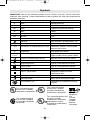
IMPORTANT: Some of the following symbols may be used on your tool. Please study them
and learn their meaning. Proper interpretation of these symbols will allow you to operate the
tool better and safer.
Symbol Name Designation/Explanation
V Volts Voltage (potential)
A Amperes Current
Hz Hertz Frequency (cycles per second)
W Watt Power
kg Kilograms Weight
min Minutes Time
s Seconds Time
Diameter Size of drill bits, grinding wheels, etc.
n
0
No load speed Rotational speed, at no load
.../min Revolutions or reciprocation per minute Revolutions, strokes, surface speed,
orbits etc. per minute
0 Off position Zero speed, zero torque...
1, 2, 3, ... Selector settings Speed, torque or position settings.
I, II, III, Higher number means greater speed
Infinitely variable selector with off Speed is increasing from 0 setting
Arrow Action in the direction of arrow
Alternating current Type or a characteristic of current
Direct current Type or a characteristic of current
Alternating or direct current Type or a characteristic of current
Class II construction Designates Double Insulated
Construction tools.
Earthing terminal Grounding terminal
Warning symbol
Alerts user to warning messages
Ni-Cad RBRC seal
Designates Ni-Cad battery recycling
program
Symbols
A
0
A
0
A
0
A
0
A
A
A
This symbol designates
that this tool is listed by
Underwriters Laboratories.
This symbol designates
that this tool is listed by
the Canadian Standards
Association.
This symbol designates
that this tool is listed to
Canadian Standards by
Underwriters Laboratories.
This symbol
designates
that
this tool
complies
to NOM
Mexican
Standards.
This symbol designates that
this tool is listed by
Underwriters Laboratories,
and listed to Canadian
Standards by Underwriters
Laboratories.
SM 1619X01359 02-06 2/16/06 1:50 PM Page 6

-7-
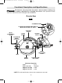
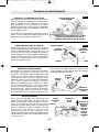
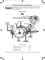
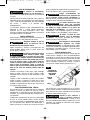
Functional Description and Specifications
Disconnect the plug from the power source before making any
a
ssembly, adjustments or changing accessories
.
Such preventive safety
measures reduce the risk of starting the tool accidentally.
!
WARNING
Circular Saw
AUXILIARY
HANDLE
UPPER
GUARD
LOWER
GUARD
LOWER GUARD
LIFT LEVER
FOOT
DEPTH
ADJUSTMENT
LEVER
BEVEL
ADJUSTMENT
LEVER
FIG. 1
CALIBRATED
BEVEL
QUADRANT
TRIGGER
SWITCH
Maximum Capacities
Blade
8-1/4"
Blade arbor hole
Diamond
Depth of cut at 90° 2-7/8"
Depth of cut at 60° 1-1/2"
Depth of cut at 45° 2-1/4"
NOTE: For tool specifications refer to the nameplate on your tool.
ALIGNMENT MARK
60° MARK TO BE ADJUSTED PRIOR TO
BEVEL ADJUSTMENT (60° ONLY)
60°
SM 1619X01359 02-06 2/16/06 1:50 PM Page 7

-8-
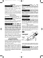
Assembly
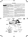
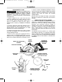
ATTACHING THE BLADE
Disconnect the plug from
the power source before
making any assembly, adjustments or
changing accessories
. Such preventive
safety measures reduce the risk of starting
the tool accidentally.
1. Press the lock button and turn wrench until
lock button engages. Saw shaft is now locked.
Continue to depress button, turn wrench
clockwise and remove BLADE STUD and
OUTER WASHER (Fig. 2).
2. Retract the lower guard all the way up into
the upper guard. While retracting the lower
guard, check operation and condition of the
LOWER GUARD SPRING.
3. Make sure the saw teeth and arrow on the
blade point in the same direction as the arrow
on the lower guard.
4. Slide blade through slot in the foot and
mount it against the INNER WASHER on the
shaft. Be sure the large diameter of the INNER
and OUTER washers lay flush against the
blade.
5. Reinstall OUTER WASHER. First tighten
BLADE STUD finger tight, then TIGHTEN
BLADE STUD 1/8 TURN (45˚) WITH THE
WRENCH PROVIDED.
Do not use wrenches with longer handles,
since it may lead to over tightening of the
blade stud.
VARI-TORQUE CLUTCH
This clutching action is provided by the friction
of the OUTER WASHER against the BLADE
and permits the blade shaft to turn when the
blade encounters excessive resistance. When
the BLADE STUD is properly tightened (as
described in No. 5 of Attaching The Blade), the
blade will slip when it encounters excessive
resistance, thus reducing saw’s tendency to
KICKBACK.
One setting may not be sufficient for cutting all
materials. If excessive blade slippage occurs,
tighten the blade stud a fraction of a turn more
(less than 1/8 turn). OVERTIGHTENING THE
BLADE STUD NULLIFIES THE EFFECTIVE-
NESS OF THE CLUTCH.
!
WARNING
LOWER GUARD
LIFT LEVER
LOWER GUARD
SPRING
UPPER GUARD
LOWER
GUARD
LOCK
BUTTON
OUTER WASHER
Large Diameter
Faces Blade
Loosen
Tighten
BLADE
STUD
INNER WASHER
Large Diameter
Faces Blade
FIG. 2
AUXILIARY
HANDLE
SM 1619X01359 02-06 2/16/06 1:50 PM Page 8

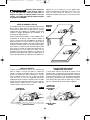
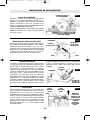
D
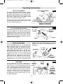
EPTH ADJUSTMENT
D
isconnect plug from power source. Loosen
the depth adjustment lever located between
the guard and handle of saw. Hold the foot
down with one hand and raise or lower saw by
the handle. Tighten lever at the depth setting
desired. Check desired depth (Fig. 3).
Not more than one tooth length of the blade
should extend below the material to be cut, for
minimum splintering (Fig. 3).
-9-
90° CUTTING ANGLE CHECK
Disconnect plug from power source. Set foot to
maximum depth of cut setting. Loosen bevel
adjustment lever, set to 0° on quadrant,
retighten bevel adjustment lever first, then the
depth adjustment lever and check for 90°
angle between the blade and bottom plane of
foot with a square (Fig. 4).
BEVEL ADJUSTMENT
Disconnect plug from power source. The foot
can be adjusted up to 45° by loosening the
bevel adjustment lever at the front of the saw.
Align to desired angle on calibrated quadrant.
Then tighten bevel adjustment first, then the
depth adjustment lever (Fig. 5). For 60° cuts,
loosen depth adjustment lever, align 60° mark
on depth bracket with mark on housing and
tighten lever (Fig. 1). Then loosen bevel
adjustment lever, depress 45° stop spring,
adjust foot to 60° and tighten lever (Fig. 5).
Because of the increased amount of blade
engagement in the work and decreased
stability of the foot, blade binding may occur.
Keep the saw steady and the foot firmly on the
workpiece.
Operating Instructions
BLADE
90°
FOOT
BEVEL
ADJUSTMENT
LEVER
QUADRANT
FIG. 4
0°
QUADRANT
BEVEL
ADJUSTMENT
LEVER
FIG. 5
LINE GUIDE
For a straight 90° cut, use the large notch in
the foot. For 45° bevel cuts, use the small
notch (Fig. 6). The cutting guide notch will
give an approximate line of cut. Make sample
cuts in scrap lumber to verify actual line of cut.
This will be helpful because of the number of
different blade types and thicknesses
available. To ensure minimum splintering on
the good side of the material to be cut, face
the good side down.
FIG. 6
FOOT
45° / 60°
BEVEL
CUTS
90°
VERTICAL
CUTS
45° STOP
SPRING
45° STOP
SPRING
PUSH
45°STOP
SPRING IN
DIRECTION
OF ARROW
FOR 60°
BEVEL
ADJUSTM
ENT
FIG. 3
DEPTH ADJUSTMENT
LEVER
ONE TOOTH LENGTH SHOULD
PENETRATE WOOD FOR
MINIMUM SPLINTERING
SM 1619X01359 02-06 2/16/06 1:50 PM Page 9

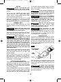
SWITCH
When starting the tool,
hold it with both hands.
The torque from the motor can cause the tool
to twist.
To turn tool “ON”, squeeze the trigger switch.
To turn the tool “OFF”, release the trigger
switch, which is spring loaded and will return
to the off position automatically.
Your saw should be running at full speed
BEFORE starting the cut, and turned off only
AFTER completing the cut. To increase switch
life, do not turn switch on and off while cutting.
GENERAL CUTS
Always hold the saw handle with one hand
and the auxiliary handle or housing with the
other.
Always be sure either hand
does not interfere with the
free movement of the lower guard.
Maintain a firm grip and operate the switch
with a decisive action. Never force the saw.
Use light and continuous pressure.
After completing a cut and
the trigger has been
released, be aware of the necessary time it
takes for the blade to come to a complete
stop during coast down. Do not allow the
saw to brush against your leg or side,
since the lower guard is retractable, it
could catch on your clothing and expose
the blade. Be aware of the necessary blade
exposures that exist in both the upper and
lower guard areas.
When cutting is interrupted, to resume cutting:
squeeze the trigger and allow the blade to
reach full speed, re-enter the cut slowly and
resume cutting.
When cutting across the grain, the fibers of
the wood have a tendency to tear and lift.
Advancing the saw slowly minimizes this
effect. For a finished cut, a cross cut blade or
miter blade is recommended.
CUTTING MASONRY/METAL
This tool is not recommended for continuous
and general usage with metal or masonry cut-
off wheels. If you use your saw for cutting
these materials, use the appropriate wheel for
the material being cut.
When cutting masonry, do not cut a depth of
more than 1/4 inch (6 mm). Make successive
passes to achieve desired depth. Apply a light
forward pressure. Do not overload motor.
Disconnect plug from power source and clean
dust from air vents frequently. Metal cutting is
done at full depth.
Clean guards frequently to
assure a rapid return of
lower guard.
The lower guard may become
sluggish when cutting masonry materials.
Abrasive Cut Off Wheels
must have a maximum
safe operating speed greater than the “no
load RPM” marked on the tool’s
nameplate.
Wheels running over the rated
speed can fly apart and cause injury.
Do not use the abrasive
cut off wheel near
flammable materials.
Sparks from the
wheel could ignite these materials.
This machine is not
intended to be used with
Wet Diamond Wheels.
Using water or other
liquid coolants with this machine may result
in electrocution or shock. Use of Dry
Diamond Wheels is acceptable.
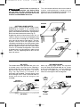
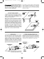
POCKET CUTS
Disconnect the plug from the power source
before making adjustments. Set depth adjust-
ment according to material to be cut. Tilt saw
forward with cutting guide notch lined up with
the line you’ve drawn. Raise the lower guard,
using lift lever and hold the saw by the front and
rear handles (Fig. 7).
With the blade just clearing the material to be
cut, start the motor. Gradually lower the back
end of saw using the front end of the foot as the
hinge point.
As blade starts cutting the
material, release the lower
guard immediately.
When the foot rests flat on
the surface being cut, proceed cutting in forward
direction to end of cut.
-10-
!
WARNING
!
WARNING
!
WARNING
!
WARNING
!
WARNING
!
WARNING
!
WARNING
!
WARNING
LOWER GUARD
LIFT LEVER
LINE
GUIDE
FOOT
FIG. 7
SM 1619X01359 02-06 2/16/06 1:50 PM Page 10

Allow blade to come to a
complete stop before lifting
the saw from cut. Also, never pull the saw
backward since blade will climb out of the
material and KICKBACK will occur.
Turn saw around and finish the cut in the normal
manner, sawing forward. If corners of your
pocket cut are not completely cut through, use a
jigsaw or hand saw to finish the corners.
-11-
RIP CUTS
The combination blade provided with your saw
is for both cross cuts and rip cuts. Ripping is
cutting lengthwise with the grain of the wood.
Rip cuts are easy to do with a rip fence
(Fig. 10). Rip Fence is available as an
accessory (not included). To attach fence, insert
fence through slots in foot to desired width as
shown and secure with the wing nut (not
included).
RIP BOARD GUIDE
When rip cutting large sheets, the rip fence
may not allow the desired width of cut. Clamp
or nail a straight piece of 1" (25 mm) lumber to
the sheet as a guide (Fig. 11). Use the right
side of the foot against the board guide.
FIG. 10
FIG. 11
RIP FENCE
DESIRED
WIDTH OF CUT
DESIRED
LINE
OF CUT
RIP
BOARD
GUIDE
CUTTING LARGE SHEETS
Large sheets and long boards sag or bend,
depending on support. If you attempt to cut
without leveling and properly supporting the
piece, the blade will tend to bind, causing KICK-
BACK and extra load on the motor (Fig. 8).
Support the panel or board close to the cut, as
shown in (Fig. 9). Be sure to set the depth of the
cut so that you cut through the sheet or board
only and not the table or work bench. The two-
by-fours used to raise and support the work
should be positioned so that the broadest sides
support the work and rest on the table or bench.
Do not support the work with the narrow sides
as this is an unsteady arrangement. If the sheet
or board to be cut is too large for a table or work
bench, use the supporting two-by-fours on the
floor and secure.
RIGHT
FIG. 8
WRONG
FIG. 9
!
WARNING
SM 1619X01359 02-06 2/16/06 1:50 PM Page 11

-12-
Service
Preventive maintenance
performed by unauthorized
personnel may result in misplacing of
internal wires and components which
could cause serious hazard.
We
recommend that all tool service be performed
by a Skil Factory Service Center or
Authorized Skil Service Station.
TOOL LUBRICATION
Your Skil tool has been properly lubricated and
is ready to use. However it is recommended
that the gears be relubricated only with Skil
lubricants: No. 80111 (8 oz. tube), No. 80112
(pint) or No. 80113 (1/2 gal. can).
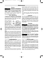
Always check the
oil level before
using the saw. To
check and add oil:
Remove plug from
power source and
place the saw’s foot on a horizontal surface.
Remove oil plug using the same wrench used
to remove the saw blade. The oil level should
never be below bottom threads in the housing.
When adding oil, fill until oil starts to run out of
oil hole at arrow on housing and replace oil
plug.
NOTE: If oil is extra dirty or thick, replace the
plug and run the saw for one minute to warm
up the oil. Then remove oil plug and turn saw
upside down, to remove all oil. Fill housing with
kerosene. Replace plug and run for one
minute to flush out the gear housing. Drain out
the kerosene and add fresh Skil lubricant. With
a new saw, change the oil after the first ten
hours of use.
CARBON BRUSHES
The brushes and commutator in your tool have
been engineered for many hours of
dependable service. To maintain peak
efficiency of the motor, we recommend every
two to six months the brushes be examined.
The brushes should be free from dust and dirt.
Brushes should be replaced when they have
worn down to 3/16" in length. The brushes
should slide freely in and out of the holders
without sticking.
To check brushes: Disconnect plug from
power source. Unscrew the brush caps on the
motor housing and lift out the brushes; note
which way they face, so that the brushes can
be returned to their original position. Clean the
brush holder openings with compressed air or
a clean cloth and replace the brushes and
caps.
Only genuine Skil replacement brushes
specially designed for your tool should be
used.
BEARINGS
After about 300-400 hours of operation, or at
every second brush change, the bearings
should be replaced at Skil Factory Service
Center or Authorized Skil Service Station.
Bearings which become noisy (due to heavy
load or very abrasive material cutting) should
be replaced at once to avoid overheating or
motor failure.
Cleaning
To avoid accidents always
disconnect the tool from
the power supply before cleaning or
performing any maintenance.
The tool may
be cleaned most effectively with compressed
dry air.
Always wear safety goggles when
cleaning tools with compressed air.
Ventilation openings and switch levers must
be kept clean and free of foreign matter. Do
not attempt to clean by inserting pointed
objects through openings.
Certain cleaning agents
and solvents damage
plastic parts.
Some of these are: gasoline,
carbon tetrachloride, chlorinated cleaning
solvents, ammonia and household detergents
that contain ammonia.
CARE OF BLADES
Blades become dull even from cutting regular
lumber. If you find yourself forcing the saw
forward to cut instead of just guiding it through
the cut, chances are the blade is dull or coated
with wood pitch.
When cleaning gum and wood pitch from
blade, unplug the saw and remove the blade.
Remember, blades are designed to cut, so
handle carefully. Wipe the blade with kerosene
or similar solvent to remove the gum and pitch.
Unless you are experienced in sharpening
blades, we recommend you do not try.
Maintenance
!
CAUTION
OIL
PLUG
OIL
LEVEL
!
WARNING
!
WARNING
SM 1619X01359 02-06 2/16/06 1:50 PM Page 12

-13-
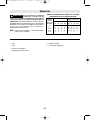
Accessories
If an extension cord is
n
ecessary, a cord with
adequate size conductors that is capable
of carrying the current necessary for your
tool must be used.
This will prevent
excessive voltage drop, loss of power or
overheating. Grounded tools must use 3-wire
extension cords that have 3-prong plugs and
receptacles.
NOTE: The smaller the gauge number, the
heavier the cord.
R
ECOMMENDED SIZES OF EXTENSION CORDS
1
20 VOLT ALTERNATING CURRENT TOOLS
!
WARNING
* Blade
* Wrench
** Carrying case
** Rip Fence
(*= standard equipment)
(**= optional accessories)
T
ool’s
A
mpere
R
ating
Cord Size in A.W.G.
W
ire Sizes in mm
2
3-6
6
-8
8
-10
10-12
12-16
1
8 16 16 14 0.75 0.75 1.5 2.5
18 16 14 12 0.75 1.0 2.5 4.0
18 16 14 12 0.75 1.0 2.5 4.0
1
6 16 14 12 1.0 2.5 4.0 —
14 12 — — — — — —
2
5 50 100 150 15 30 60 120
C
ord Length in Feet Cord Length in Meters
SM 1619X01359 02-06 2/16/06 1:50 PM Page 13

-14-
Vous devez lire et comprendre toutes les instructions. Le non-respect, même partiel,
des instructions ci-après entraîne un risque de choc életrique, d'incendie et/ou de
blessures graves.
CONSERVEZ CES INSTRUCTIONS
AVERTISSEMENT
!
Aire de travail
Veillez à ce que l'aire de travail soit propre et bien
éclairée. Le désordre et le manque de lumière
favorisent les accidents.
N'utilisez pas d'outils électriques dans une
atmosphère explosive, par exemple enprésence de
liquides, de gaz ou de poussières inflammables. Les
outils électriques créent des étincelles qui pourraient
enflammer les poussières ou les vapeurs.
Tenez à distance les curieux, les enfants et les
visiteurs pendant que vous travaillez avec un outil
électrique. Ils pourraient vous distraire et vous faire
faire une fausse manoeuvre.
Sécurité électrique
Les outils avec mise à la terre doivent être branchés
sur une prise installée correctement et reliée à la
terre conformément à toutes les normes et décrets.
N’enlevez jamais la fiche de terre et ne modifiez
jamais la prise. N’utilisez jamais d’adaptateur de
prise. Si vous n’êtes pas sûr que votre prise est
correctement reliée à la terre, consultez un
électricien. Si l’outil présente une avarie électrique ou
tombe en panne, le circuit de terre sert de chemin à
faible résistance pour conduire le courant et l’empêcher
de passer à travers l’utilisateur. Un outil incorrectement
relié à la terre risque de causer un choc électrique, des
brûlures ou une électrocution. Les outils avec mise à la
terre sont munis d’un cordon à trois fils et d’une prise à
trois fiches. Avant de brancher l'outil, assurez-vous que
la tension de la prise correspond, à celle indiquée sur la
plaque signalétique. N'utilisez pas d'outils prévus pour
courant alternatif seulement avec une source de courant
continu.
Évitez tout contact corporel avec des surfaces mises à
la terre (tuyauterie, radiateurs, cuisinières,
réfrigérateurs, etc.). Le risque de choc électrique est
plus grand si votre corps est encontact avec la terre.Si
l'utilisation de l'outil électrique dans un endroit humide
est inévitable, un disjoncteur de fuite à la terre doit être
utilisé pour alimenter votre outil. Des chaussures et des
gants en caoutchouc d'électricien contribueront à
accroître davantage votre sécurité personnelle.
N'exposez pas les outils électriques à la pluie ou à
l'eau. La présence d'eau dans un outil électrique
augmente le risque de choc électrique.
Ne maltraitez pas le cordon. Ne transportez pas l'outil
par son cordon et ne débranchez pas la fiche en tirant
sur le cordon. N'exposez pas le cordon à la chaleur, à
des huiles, à des arêtes vives ou à des pièces en
mouvement. Remplacez immédiatement un cordon
endommagé.
Un cordon endommagé augmente le
risque de choc électrique.
Lorsque vous utilisez un outil électrique à l'extérieur,
employez un prolongateur pour l'extérieur marqué
« W-A » ou « W ». Ces cordons sont faits pour être
utilisés à l'extérieur et réduisent le risque de choc
électrique. Reportez-vous aux « Dimensions
recommandées des cordons de rallonge » dans la
section Accessoires de ce manuel.
Sécurité des personnes
Restez alerte, concentrez-vous sur votre travail et
faites preuve de jugement. N'utilisez pas un outil
électrique si vous êtes fatigué ou sous l'influence de
drogues, d'alcool ou de médicaments. Un instant
d'inattention suffit pour entraîner des blessures graves.
Habillez-vous convenablement. Ne portez ni
vêtements flottants ni bijoux. Confinez les cheveux
longs. N'approchez jamais les cheveux, les
vêtements ou les gants des pièces en mouvement.
Des vêtements flottants, des bijoux ou des cheveux
longs risquent d'être happés par des pièces en
mouvement. Gardez les poignées sèches, propres et
exemptes d'huile et de graisse.
Méfiez-vous d'un démarrage accidentel. Avant de
brancher l'outil, assurez-vous que son interrupteur est
sur ARRÈT. Le fait de transporter un outil avec le doigt
sur la détente ou de brancher un outil dont l'interrupteur
est en position MARCHE peut mener tout droit à un
accident.
Enlevez les clés de réglage ou de serrage avant de
démarrer l'outil. Une clé laissée dans une pièce
tournante de l'outil peut provoquer des blessures.
Ne vous penchez pas trop en avant. Maintenez un bon
appui et restez en équilibre entout temps.
Une bonne
stabilité vous permet de mieux réagir à une situation
inattendue.
Utilisez des accessoires de sécurité. Portez toujours
des lunettes ou une visière. Selon les conditions,
portez aussi un masque antipoussière, des bottes de
sécurité antidérapantes, un casque protecteur et/ou un
appareil antibruit.
Règles de Sécurité Générales
SM 1619X01359 02-06 2/16/06 1:50 PM Page 14

-15-
Utilisation et entretien des outils
Immobilisez le matériau sur une surface stable au
moyen de brides ou de toute autre façon adéquate. Le
fait de tenir la pièce avec la main ou contre votre corps
offre une stabilité insuffisante et peut amener un
dérapage de l'outil.
Ne forcez pas l'outil. Utilisez l'outil approprié à la
tâche. L'outil correct fonctionne mieux et de façon plus
sécuritaire. Respectez aussi la vitesse de travail qui lui
est propre.
N'utilisez pas un outil si son interrupteur est bloqué.
Un outil que vous ne pouvez pas commander par son
interrupteur est dangereux et doit être réparé.
Débranchez la fiche de l'outil avant d'effectuer un
réglage, de changer d'accessoire oude ranger l'outil.
De telles mesures préventives de sécurité réduisent le
risque de démarrage accidentel de l'outil.
Rangez les outils hors de la portée des enfants et
d'autres personnes inexpérimentées. Les outils sont
dangereux dans les mains d'utilisateurs novices.
Prenez soin de bien entretenir les outils. Les outils de
coupe doivent être toujours bien affûtés et propres.
Des outils bien entretenus, dont les arêtes sont bien
tranchantes, sont moins susceptibles de coincer et plus
faciles à diriger.Toute altération ou modification
constitue un usage erroné et peut causer un danger.
Soyez attentif à tout désalignement ou coincement
des pièces en mouvement, à tout bris ou à toute autre
condition préjudiciable au bon fonctionnement de
l'outil. Si vous constatez qu'un outil est endommagé,
faites-le réparer avant de vous en servir. De
nombreux accidents sont causés par des outils en
mauvais état. Élaborez un calendrier d'entretien
périodique de votre outil.
N'utilisez que des accessoires que le fabricant
recommande pour votre modèle d'outil. Certains
accessoires peuvent convenir à un outil, mais être
dangereux avec un autre.
Réparation
La réparation des outils électriques doit être confiée
à un réparateur qualifié. L'entretien ou la réparation
d'un outil électrique par un amateur peut avoir des
conséquences graves. Ainsi, des fils internes peuvent
être mal placés ou pincés, des ressorts de rappel de
protecteur peuvent être montés erronément.
Pour la réparation d'un outil, n'employez que des
pièces de rechange d'origine. Suivez les directives
données à la section « Réparation » de ce manuel.
L'emploi de pièces non autorisées ou le non-respect
des instructions d'entretien peut créer un risque de
choc électrique ou de blessures. Certains agents
nettoyants tels qu'essence, tétrachlorure de carbone,
ammoniac, etc., peuvent abîmer les pièces en plastique.
Tenez les mains à l'écart de l'aire
de coupe et de la lame. Gardez
votre deuxième main sur la poignée auxiliaire ou le
carter du moteur. Si les deux mains tiennent la scie,
elles ne peuvent être coupées par la lame. Tenez la scie
fermement pour prévenir une perte de contrôle. Les
figures de ce manuel illustrent le support manuel
typique de la scie. Ne JAMAIS placez votre main
derrière la lame de la scie car le rebond pourrait faire
sauter la scie vers l'arrière par-dessus votre main.
Gardez votre corps positionné d'un côté ou de l'autre
de la lame de scie, mais non dans le prolongement
de la lame de scie.
Le REBOND pourrait faire sauter la
scie vers l'arrière. (Voir « Causes et prévention, par
l'opérateur, du rebond »).
N'introduisez pas la main sous l'ouvrage. Le garde ne
peut vous protéger de la lame sous l'ouvrage. Ne tentez
pas d'enlever des matériaux coupés lorsque la lame est
en mouvement.
Vérifiez le garde inférieur pour vous assurer qu'il
ferme adéquatement avant chaque usage. N'utilisez
pas la scie si le garde inférieur ne bouge pas
librement et ne ferme pas instantanément. Ne pincez
ou ne fixez jamais le garde inférieur en position
ouverte.
Si la scie tombe par mégarde, le garde
inférieur peut être plié. Levez le garde inférieur
uniquement à l'aide de la levier de levage du garde
inférieur, et assurez-vous qu'il bouge librement et ne
vient pas en contact avec la lame ou aucune autre pièce,
sous tous les angles et profondeurs de coupe.
Vérifiez le fonctionnement du ressort du rappel du
garde inférieur. Si le garde et le ressort ne
fonctionnent pas adéquatement, ils doivent être
réparés avant usage.
Le garde inférieur peut
fonctionner paresseusement en raison de pièces
abîmées, de dépôts gommeux ou d'une accumulation
de débris. Débranchez la fiche de la prise de courant. À
intervalles périodiques, déposez la lame, nettoyez les
gardes supérieur et inférieur et la région du moyeu à
l'aide de kérosène et essuyez pour sécher, ou nettoyez
en soufflant de l'air comprimé.
Consignes de sécurité pour scies circulaires
DANGER
!
SM 1619X01359 02-06 2/16/06 1:50 PM Page 15

Le garde inférieur doit être rétracté manuellement
uniquement pour des coupes spéciales telles que les
« coupes en poche » et les « coupes combinées ».
Levez le garde inférieur à l'aide de la levier de levage
du garde inférieur. Le garde inférieur doit être relâché
dès que la lame pénètre dans l'ouvrage. Pour toutes les
autres opérations de sciage, le garde inférieur doit
fonctionner automatiquement.
Assurez-vous toujours que le garde inférieur couvre la
lame avant de déposer la scie sur l'établi ou le
plancher. Une lame non protégée, qui continue à
marcher par inertie, fera reculer la scie, coupant ainsi
tout ce qui est sur son chemin. Sachez le temps qu'il
faut pour que la lame s'arrête après relâchement de
l'interrupteur.
Ne tenez JAMAIS la pièce à couper dans vos mains ou
sur vos jambes. Il importe de supporter l'ouvrage
adéquatement afin de minimiser l'exposition corporelle,
le grippage de lame ou la perte de contrôle.
Tenez l'outil par les surfaces isolées de préhension
en effectuant une opération au cours de laquelle
l'outil de coupe peut venir en contact avec des fils
dissimulés ou son propre cordon. Le contact avec un
fil sous tension rendra également les parties métalliques
exposées de l'outil sous tension et causera des chocs à
l'opérateur.
En refendant, utilisez toujours un guide de refente ou
une règle. Ceci améliore l'exactitude de la coupe et
réduit les possibilités de grippage de la lame.
Utilisez toujours des lames avec trous d'arbre de la
dimension et de la forme appropriées (en diamant par
rapport à rondes). Les lames qui ne se marient pas
avec le système de montage de la scie ne tourneront
pas rond. Il en résultera une perte de contrôle et un
mauvais fonctionnement du vari-torque.
N'utilisez jamais des rondelles ou boulons de lame
abîmés ou incorrects. Les rondelles et les boulons de
lame ont été conçus spécialement pour votre scie, pour
une performance optimale et pour un fonctionnement
des plus sûrs. Les rondelles de lame et le boulon sur
votre scie ont été conçus de manière à travailler comme
« EMBRAYAGE À COUPLE VARIABLE ». Comprenez le
fonctionnement et les réglages de l'EMBRAYAGE À
COUPLE VARIABLE car le réglage approprié de
l'EMBRAYAGE, combiné au maniement ferme de la scie,
vous permettra de contrôler le REBOND.
Ne faites pas fonctionner la scie tout en la portant à
votre côté. Le garde inférieur peut s'ouvrir au contact
avec vos vêtements.
Un contact accidentel avec la lame
de scie en rotation pourrait provoquer des blessures
graves.
Suivant l'usage, l'interrupteur peut ne pas durer aussi
longtemps que la scie. Si l'interrupteur fait défaut en
position d'arrêt, la scie peut ne pas se mettre en
marche. S'il devient défectueux pendant que la scie
est en marche, la scie peut ne pas s'arrêter. Dans l'un
ou l'autre cas, débranchez la scie immédiatement et ne
l'utilisez pas avant qu'elle ne soit réparée.
C
ette scie circulaire ne doit pas être montée sur une
table et convertie en scie de table.
Les scies
circulaires ne sont pas conçues ni destinées à être
utilisées comme scies de table.
CAUSES ET PRÉVENTION, PAR L'OPÉRATEUR,
DU REBOND :
Le rebond est une réaction soudaine à une lame de scie
pincée, grippée ou mal alignée, amenant ainsi la scie
non contrôlée à lever et ressortir de l'ouvrage en
direction de l'opérateur.
Lorsque la lame est pincée ou grippée fermement par le
trait de scie qui se referme, la lame bloque et la réaction
du moteur ramène rapidement l'outil en direction de
l'opérateur.
Si la lame devient tordue ou mal alignée dans la coupe,
les dents du bord arrière de la lame peuvent s'enfoncer
dans la surface supérieure du bois, amenant ainsi la
lame à sortir du trait de scie et à revenir vers
l'opérateur.
Le rebond est le résultat d'une utilisation erronée de
l'outil et/ou de méthodes ou de conditions de
fonctionnement incorrectes, et on peut l'éviter en
prenant les précautions appropriées, comme indiqué ci-
après :
Maintenez une prise ferme avec les deux mains sur la
scie et positionnez votre corps et votre bras de
manière à résister aux forces de REBOND. L'opérateur
peut contrôler les forces de rebond si les précautions
appropriées sont prises.
Lorsque la lame grippe ou lorsqu'une coupe est
interrompue pour quelque motif que ce soit, relâchez
la gâchette et tenez la scie sans bouger dans
l'ouvrage jusqu'à ce que la lame s'arrête
complètement. Ne tentez jamais de retirer la scie de
l'ouvrage ou de tirer la scie vers l'arrière pendant que
la lame est en mouvement, ce qui pourrait provoquer
un REBOND. Recherchez la cause du grippage de lame
et prenez les mesures nécessaires pour le corriger. Le
-16-
REBOND
EMBRAYAGE
VARI-TORQUE
SM 1619X01359 02-06 2/16/06 1:50 PM Page 16

bois mouillé, le bois vert ou le bois traité par pression
nécessitent une attention spéciale durant la coupe pour
prévenir le REBOND. Évitez de couper les clous.
Recherchez et enlevez tous les clous du bois avant de
couper.
Lorsque vous remettez une scie en marche dans un
ouvrage, centrez la lame de scie dans le trait de scie
et assurez-vous que les dents de scie ne sont pas
engagées dans l'ouvrage. Si la lame de scie grippe, elle
peut remonter ou REBONDIR depuis l'ouvrage lorsque
la scie est remise en marche.
Supportez les gros panneaux pour minimiser le risque
de pincement de lame et de REBOND. Les gros
panneaux ont tendance à s'affaisser sous leur propre
poids. Des supports doivent être placés sous le panneau
des deux côtés, près de la ligne de coupe et près du
bord du panneau. Voir « Coupe de gros panneaux»
dans ce manuel.
N'utilisez pas une lame émoussée ou abîmée. Les
lames non affûtées ou réglées de façon inappropriée
produisent un trait de scie étroit, ce qui cause une
friction excessive, un grippage de lame et un REBOND.
Les boutons de blocage de réglage de biseau et de
profondeur de lame doivent être serrés et fermes
avant de pratiquer la coupe. Un déplacement du
réglage de lame durant la coupe peut causer un
grippage et un REBOND. L'utilisation de la scie avec un
réglage excessif de profondeur de coupe accroît la
charge sur l'outil et la sensibilité à la torsion de la lame
dans le trait de scie. Elle accroît également la surface de
lame disponible pour pincement dans des conditions de
fermeture du trait de scie.
Redoubler de prudence en pratiquant une « coupe de
poche » dans des murs existants ou autres parties
aveugles. La lame faisant saillie peut couper des objets
qui peuvent causer un REBOND.
L
es travaux à la machine
t
el que ponçage, sciage,
meulage, perçage et autres travaux du bâtiment
peuvent créer des poussières contenant des
produits chimiques qui sont des causes reconnues
de cancer, de malformation congénitale ou d’autres
problèmes reproductifs. Ces produits chimiques
sont, par exemple :
• Le plomb provenant des peintures à base de plomb,
• Les cristaux de silices provenant des briques et du
ciment et d’autres produits de maçonnerie, et
• L’arsenic et le chrome provenant des bois traités
chimiquement.
Le niveau de risque dû à cette exposition varie avec la
fréquence de ces types de travaux. Pour réduire
l’exposition à ces produits chimiques, il faut travailler
dans un lieu bien ventilé et porter un équipement de
sécurité approprié tel que certains masques à
poussière conçus spécialement pour filtrer les
particules microscopiques.
-17-
AVERTISSEMENT
!
SM 1619X01359 02-06 2/16/06 1:50 PM Page 17

-18-
Symboles
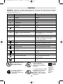
IMPORTANT : Certains des symboles suivants peuvent être utilisés sur votre outil. Veuillez les étudier et
apprendre leur signification. Une interprétation appropriée de ces symboles vous permettra d'utiliser l'outil de
façon plus efficace et plus sûre.
Symbole Nom Désignation/Explication
V Volts Tension (potentielle)
A Ampères Courant
Hz Hertz Fréquence (cycles par seconde)
W Watt Puissance
kg Kilogrammes Poids
min Minutes Temps
s Secondes Temps
Diamètre Taille des mèches de perceuse, meules,
etc.
n
0
Vitesse à vide Vitesse de rotation, à vide
.../min Tours ou mouvement alternatif par Tours, coups, vitesse en surface, orbites,
minute etc., par minute
0 Position d'arrêt Vitesse zéro, couple zéro ...
1, 2, 3, ... Réglages du sélecteur Réglages de vitesse, de couple ou de
l, ll, lll, ... position. Un nombre plus élevé signifie
une vitesse plus grande.
Sélecteur variable à l'infini avec arrêt La vitesse augmente depuis le réglage 0
Flèche Action dans la direction de la flèche
Courant alternatif Type ou caractéristique du courant
Courant continu Type ou caractéristique du courant
Courant alternatif Type ou caractéristique du courant
ou continu
Construction classe II Désigne des outils construits avec double
isolation
Borne de terre Borne de mise à la terre
Symbole d'avertissement Alerte l'utilisateur aux messages
d'avertissement.
Sceau Ni-Cad RBRC Désigne le programme de recyclage des piles
Ni-Cad.
A
0
A
0
A
0
A
0
A
A
A
Ce symbole signifie que cet
outil est approuvé par
Underwriters Laboratories.
Ce symbole signifie que cet
outil est approuvé par
l'Association canadienne de
normalisation.
Ce symbole signifie que
cet outil est approuvé
conformément aux normes
canadiennes par Underwriters
Laboratories.
Ce symbole
signifie que
cet outil se
conforme aux
normes
mexicaines
NOM.
Ce symbole signifie que cet outil
est approuvé par Underwriters
Laboratories et qu’il a été
homologué selon les normes
canadiennes par Underwriters
Laboratories.
SM 1619X01359 02-06 2/16/06 1:50 PM Page 18

-19-
Description fonctionnelle et spécifications
Débranchez la fiche de la prise de courant avant d'effectuer quelque assemblage
ou réglage que ce soit ou de changer les accessoires. Ces mesures de sécurité
préventive réduisent le risque d'une mise en marche accidentelle de l'outil.
A
VERTISSEMENT
!
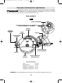
Scie circulaire
POIGNÉE
AUXILIAIRE
GARDE
SUPÉRIEUR
GARDE
INFÉRIEUR
LEVIER DE LEVAGE DU
GARDE INFÉRIEUR
SEMELLE
LEVIER DE RÉGLAGE
DE LA PROFONDEUR
LEVIER DE
RÉGLAGE DU
BISEAU
FIG. 1
SECTEUR GRADUÉ
DE BISEAU
GÂCHETTE
Capacités maximales
Lame 210 mm
Moyeu de lame Diamant
Profondeur de coupe à 90
°
73 mm
Profondeur de coupe à 60
°
38 mm
Profondeur de coupe à 45
°
57 mm
REMARQUE : Pour spécifications de l'outil, reportez-vous à la plaque signalétique de votre outil.
REPÈRE D’ALIGNEMENT
LA RÈGLAGE AU REPÈRE DE 60° DOIT PRÉCÉDER LE
RÈGLAGE DU BISEAU (60° SEULEMENT)
60°
SM 1619X01359 02-06 2/16/06 1:50 PM Page 19

-20-
Assemblage
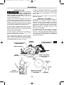
MONTAGE DE LA LAME
Débranchez la fiche de la
prise de courant avant
d'effectuer quelque assemblage ou réglage que ce
soit ou de changer les accessoires. Ces mesures de
sécurité préventive réduisent le risque d'une mise en
marche accidentelle de l'outil.
1. Appuyez sur le bouton de verrouillage et tournez la clé
jusqu’à enclenchement du dispositif de verrouillage, ce
qui a pour effet d’immobiliser l’arbre de la scie. Tout en
maintenant le bouton enfoncé, tournez la clé dans le
sens des aiguilles d’une montre et enlevez le GOUJON
DE LA LAME et la RONDELLE EXTÉRIEURE (Fig. 2).
2. Faites remonter le garde inférieur de la lame en le
laissant coulisser totalement à l’intérieur du capot.
Profitez-en pour vérifier l’état et le fonctionnement du
RESSORT DU GARDE INFÉRIEUR.
3. Assurez-vous que les dents de la scie et la flèche sur
la lame sont dirigées dans le même sens que la flèche
figurant sur le garde inférieur de la lame.
4. Glissez la lame dans la fente de la semelle et placez-la
contre la RONDELLE INTÉRIEURE de l’arbre. Assurez-
vous que le plus grand côté des rondelles INTÉRIEURE
et EXTÉRIEURE appuie carrément sur la lame.
5. Reposez la RONDELLE EXTÉRIEURE. Vissez d’abord
le GOUJON DE LA LAME à la main, puis SERREZ-LE DE
1/8 DE TOUR (45°) AU MOYEN DE LA CLÉ LIVRÉE
AVEC LA SCIE.
N’utilisez pas de clés plus longues car vous risqueriez de
trop serrer le goujon.
EMBRAYAGE « VARI-TORQUE »
L’embrayage est assuré par la friction de la RONDELLE
EXTÉRIEURE sur la LAME et il permet à l’arbre de
continuer à tourner si la lame éprouve une résistance
excessive. Si le GOUJON DE LA LAME est correctement
serré (tel qu’il est expliqué à l’étape 5 du chapitre intitulé
Montage de la lame), la lame glissera sur son arbre
quand elle éprouve une résistance excessive, ce qui
réduit le risque de REBOND.
Il est possible qu’un seul et même réglage ne convienne
pas à tous les matériaux. En cas de glissement exagéré
de la lame, resserrez-en légèrement le goujon (moins de
1/8 de tour). LE SERRAGE EXCESSIF DU GOUJON DE
LA LAME REND LE DISPOSITIF DE DÉBRAYAGE
ABSOLUMENT INUTILE.
AVERTISSEMENT
!
LEVIER DE RÉGLAGE DU
GARDE INFÉRIEUR
RESSORT DE RAPPEL DU
GARDE INFÉRIEUR
GARDE SUPÉRIEUR
GARDE
INFÉRIEUR
BOUTON
DE VERROUILLAGE
RONDELLE EXTÉRIEURE
Grand diamètre orienté
vers la lame
DESSERRER
SERRER
GOUJON DE
LAME
RONDELLE INTÉRIEURE
Grand diamètre orienté
vers la lame
FIG. 2
POIGNÉE
AUXILIAIRE
SM 1619X01359 02-06 2/16/06 1:50 PM Page 20
La page est en cours de chargement...
La page est en cours de chargement...
La page est en cours de chargement...
La page est en cours de chargement...
La page est en cours de chargement...
La page est en cours de chargement...
La page est en cours de chargement...
La page est en cours de chargement...
La page est en cours de chargement...
La page est en cours de chargement...
La page est en cours de chargement...
La page est en cours de chargement...
La page est en cours de chargement...
La page est en cours de chargement...
La page est en cours de chargement...
La page est en cours de chargement...
La page est en cours de chargement...
La page est en cours de chargement...
La page est en cours de chargement...
La page est en cours de chargement...
-
 1
1
-
 2
2
-
 3
3
-
 4
4
-
 5
5
-
 6
6
-
 7
7
-
 8
8
-
 9
9
-
 10
10
-
 11
11
-
 12
12
-
 13
13
-
 14
14
-
 15
15
-
 16
16
-
 17
17
-
 18
18
-
 19
19
-
 20
20
-
 21
21
-
 22
22
-
 23
23
-
 24
24
-
 25
25
-
 26
26
-
 27
27
-
 28
28
-
 29
29
-
 30
30
-
 31
31
-
 32
32
-
 33
33
-
 34
34
-
 35
35
-
 36
36
-
 37
37
-
 38
38
-
 39
39
-
 40
40


Skil HD5860 Manuel utilisateur
- Catégorie
- Scies circulaires
- Taper
- Manuel utilisateur
- Ce manuel convient également à
dans d''autres langues
- English: Skil HD5860 User manual
- español: Skil HD5860 Manual de usuario
Documents connexes
Autres documents
-
Bosch Power Tools 1678 Manuel utilisateur
-
Bosch CS20 Le manuel du propriétaire
-
-
-
SKILSAW SPT67WM-22 Mode d'emploi
-
-
-