Faber Scirocco Lux 30 BK Guide d'installation
- Catégorie
- Hottes
- Taper
- Guide d'installation
Ce manuel convient également à

SCLX3015BKNB-B
SCLX3615BKNB-B
SCLX3015SSNB-B
SCLX3615SSNB-B
Installation Instructions
Use and Care Information
Instructions d'installation
Utilisez et d'entretien
SCIROCCO LUX

2
READ AND SAVE THESE INSTRUCTIONS BEFORE YOU
START INSTALLING THIS RANGEHOOD
WARNING: - TO REDUCE THE RISK OF A RANGE TOP GREASE FIRE:
a) Never leave surface units unattended at high settings. Boilovers cause smoking and
greasy spillovers that may ignite. Heat oils slowly on low or medium setting.
b)AlwaysturnhoodONwhencookingathighheatorwhenambeingfood(i.e.Crepes
Suzette, Cherries Jubilee, Peppercorn Beef Flambé).
c) Clean ventilating fans frequently. Grease should not be allowed to accumulate on fan
orlter.
d) Use proper pan size. Always use cookware appropriate for the size of the surface element.
WARNING: - TO REDUCE THE RISK OF INJURY TO PERSONS IN THE EVENT OF A
RANGE TOP GREASE FIRE, OBSERVE THE FOLLOWING*:
a)SMOTHERFLAMESwithaclose-ttinglid,cookiesheet,ormetaltray,thenturnofftheburner.
BECAREFULTOPREVENTBURNS.IftheamesdonotgooutimmediatelyEVACUATE
AND CALL THE FIRE DEPARTMENT.
b) NEVER PICK UP A FLAMING PAN - You may be burned.
c) DO NOT USE WATER, including wet dishcloths or towels - a violent steam explosion will
result.
d) Use an extinguisher ONLY if:
1. You know you have a Class ABC extinguisher, and you already know how to operate it.
2. Thereissmallandcontainedintheareawhereitstarted.
3. Theredepartmentisbeingcalled.
4. Youcanghttherewithyourbacktoanexit.
* Based on "Kitchen Firesafety Tips" published by NFPA
WARNING - TO REDUCE THE RISK OF FIRE OR ELECTRIC SHOCK, do not use this fan
with any solid-state speed control device.
WARNING - TO REDUCE THE RISK OF FIRE, ELECTRICAL SHOCK, OR INJURY TO
PERSONS, OBSERVE THE FOLLOWING:
1. Use this unit only in the manner intended by the manufacturer. If you have any
questions, contact the manufacturer.
2. Before servicing or cleaning unit, switch power off at service panel and lock the
service disconnecting means to prevent power from being switched on acciden-
tally. When the service disconnecting means cannot be locked, securely fasten a
prominent warning device, such as a tag, to the service panel.
CAUTION: For General Ventilating Use Only. Do Not Use To Exhaust Hazardous or
Explosive Materials and Vapors.
WARNING - TO REDUCE THE RISK OF FIRE, ELECTRICAL SHOCK, OR INJURY TO
PERSONS, OBSERVE THE FOLLOWING:
1. InstallationWorkAndElectricalWiringMustBeDoneByQualiedPerson(s)InAccor-
dance With All Applicable Codes And Standards, Including Fire-Rated Construction.
2. Sufcient airisneededfor propercombustion andexhausting ofgases through
theue(chimney) offuelburningequipmenttopreventbackdrafting.Followthe
heating equipment manufacturer's guideline and safety standards such as those
publishedbytheNational Fire ProtectionAssociation (NFPA),and theAmerican
SocietyforHeating,RefrigerationandAirConditioningEngineers(ASHRAE),and
the local code authorities.

3
ALL WALL AND FLOOR OPENINGS WHERE THE RANGEHOOD IS INSTALLED
MUST BE SEALED.
This rangehood requires at least 24" of clearance between the bottom of the rangehood
and the cooking surface or countertop. This hood has been approved by UL at this distance
from the cooktop.
This minimum clearance may be higher depending on local building codes. For gas cooktops
and combination ranges, a minimum of 30" is recommended and may be required.
Overhead cabinets on both sides of this unit must be a minimum of 18" above the cooking
surface or countertop. Consult the cooktop or range installation instructions given by the
manufacturer before making any cutouts.
MOBILE HOME INSTALLATION The installation of this rangehood must conform to the
Manufactured Home Construction and Safety Standards, Title 24 CFR, Part 3280 (formerly
Federal Standard for Mobile Home Construction and Safety, Title 24, HUD, Part 280). See
Electrical Requirements.
• Venting system MUST terminate outside the home.
• DO NOT terminate the ductwork in an attic or other enclosed space.
• DO NOT use 4" laundry-type wall caps.
• Flexible-type ductwork is not recommended.
• DO NOT obstruct the ow of combustion and ventilation air.
• Failure to follow venting requirements may result in a re.
WARNING
!
VENTING REQUIREMENTS
Determine which venting method is best for your application. Ductwork can extend either through
the wall or the oor.
The length of the ductwork and the number of elbows should be kept to a minimum to provide ef-
cient performance. The size of the ductwork should be uniform. Do not install two elbows together.
Use duct tape to seal all joints in the ductwork system. Use caulking to seal exterior wall or oor
opening around the cap.
Flexible ductwork is not recommended. Flexible ductwork creates back pressure and air
turbulence that greatly reduces performance.
Make sure there is proper clearance within the wall or oor for exhaust duct before making cutouts.
Do not cut a joist or stud unless absolutely necessary. If a joist or stud must be cut, then a support-
ing frame must be constructed.
WARNING - To Reduce The Risk Of Fire, Use Only Metal Ductwork.
CAUTION-Toreduceriskofreandtoproperlyexhaustair,besuretoductairoutside–Do
not vent exhaust air into spaces within walls or ceilings or into attics, crawl spaces, or garages.
3. When cutting or drilling into wall or ceiling, do not damage electrical wiring and
other hidden utilities.
4. Ducted fans must always be vented to the outdoors.

4
• Electrical ground is required on this rangehood.
• If cold water pipe is interrupted by plastic, nonmetallic gaskets or other materials, DO
NOT use for grounding.
• DO NOT ground to a gas pipe.
• DO NOT have a fuse in the neutral or grounding circuit. A fuse in the neutral or
grounding circuit could result in electrical shock.
• Check with a qualied electrician if you are in doubt as to whether the rangehood is
properly grounded.
• Failure to follow electrical requirements may result in a re.
WARNING
!
State of California Proposition 65 Warning (US only)
WARNING
This product contains chemicals known to the State of California to cause cancer and birth
defects or other reproductive harm.
For more information go to www.P65Warnings.ca.gov

5
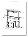
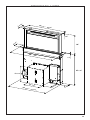
RANGEHOOD DIMENSIONS
3
11/16
“
25
1/4
“ - 31
1/4
”
4
3/4
“
3/16
“
16“
27
7/16
“
1/4
“
4“
9
13/16
“
13
1/16
“
25
9/16
“ - 31
9/16
“
13
1/16
“
30” - 36”

6
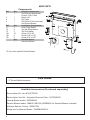
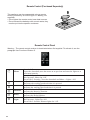
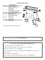
MAIN PARTS
Components
Ref. Qty. Product Components
1 1 Hood Canopy complete with:
Controls, Light, Filters.
3 1 Electric unit.
4 1 Top Frame
6 1 Duct Collar 10" duct collar used
with Remote Blowers
Ref. Qty. Installation Components
7.1 2 Lower Fixing Bracket
7.2 2 Top Side Fixing Bracket
7.3 2 Top Front Bracket
12a 16 Screws 1/8" x 3/8"
12b 6 Screws 3/16" x 5/16"
12c 8 Screws 3/16" x 9/16"
Qty. Documentation
1 Instruction Manual
10" duct collar used with Remote Blowers
AvailableAccessories(Purchasedseparately)
Recirculation Kit - sku # DUCTSCIR
Recirculation Vent Kit - Activated Charcoal Filter - FILTERSCIR
Internal Blower model - IBDD600-B
Remote Blower model - RB900, RB1200 (WIREBOX for Remote Blower included)
Wireless Remote Control - REMCTRL
Wiring box for Remote Blower - WIREBOXSCLX
Parts needed
- 6" Round Metal ductwork .
5
12b
12b

7
EN
2
24
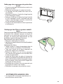
Inserting the Hood Canopy into the support surface from below
• Insert the Hood Canopy from below into the
support worktop, drilled as described above.
• With the aid of a support, lift the Hood Cano-
py until the front comes out of the Worktop.
• Insert the Brackets 7.2, as indicated in the
figure, into the slots provided and fix them
with the screws 12a provided.
• Centre the Hood Canopy with respect to the
Cooking Hob slot.
• Using the 2 screws 12c provided, fix the
Hood Canopy to the worktop and remove
the supports.
Warning:
If the cooker top is made from a material that does not allow the screws 12c to be inserted, use
a small amount of silicone to glue the Brackets 7.2 to the top and allow it to dry completely
before proceeding with installation.
1
2
The distance between the opening made for the cooker hob and the one for the suction device must
be minimum 1 3/16" - maximum 1 15/16", according to the strength of the material used for the top.
• Insert the Hood Canopy from below into the countertop
cutout, drilled as described above.
Installation Instructions
Cutout Dimensions
EN
2
23
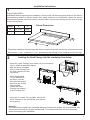
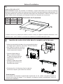
INSTALLATION
This Hood is set up to be fitted inside the kitchen unit in:
• Ducting version: Evacuation to the outside.
Sequence of operations - Installation
• Drilling the Support Surface and Fitting the Hood
• Connections
• Functional Check
• Disposal of Packaging
Drilling the Support Surface
X
812
Warning
Once the Support surface has been drilled the Hood Canopy can be installed in two ways:
• By inserting the Hood Canopy from below ( X = 106 mm ).
• By inserting the Hood Canopy from above ( X = 113 mm ).
IMPORTANT
The minimum distance between the opening for the hob and the one for the hood must be of at
least 3-5 cm according to the strength of the material used for the working top.
Y
X
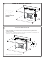
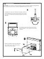
Inserting the Hood Canopy into the countertop from below
• Insert the Brackets
7.2, as indicated in
the gure, into the
slots provided and x
them with the screws
12a provided.
• Center the Hood
Canopy with respect
to the Cooktop slot.
• Using the 2 screws 12c provided, secure the
Hood Canopy to the countertop and remove
the supports.
Warning:
If the countertop is made from a material that does not allow the screws 12c to be inserted, use
a small amount of silicone to glue the Brackets 7.2 to the top and allow it to dry completely
before proceeding with installation.
• With the aid of a support,
lift the Hood Canopy until
the front comes out of the
countertop.
FOR YOUR SAFETY:
WARNING Before beginning the installation, switch power off at service panel and lock the service
disconnecting means to prevent power from being switched on accidentally. When the service
disconnecting means cannot be locked, securely fasten a prominent warning device, such as a tag,
to the service panel.
Hood X Y
30" 25 15/16" 4 5/16"
36" 31 15/16" 4 5/16"

8
EN
2
26
12c
12a
7.1
12a
7.1
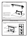
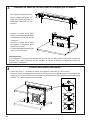
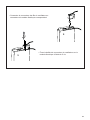
Fixing the Lower Brackets
• Screw the brackets 7.1 to the front of the Hood Canopy using the screws 12a provided.
• Before tightening the Brackets completely, make all the adjustments to allow them to rest on
the lower base of the worktop to avoid deformation of the upper brackets 7.2 as shown in the
figure.
• With the aid of a spirit level, set the Hood Canopy level vertically and fix it to the Lower
Surface using 2 screws 12c provided.
• Tighten the screws 12a completely.
3
• Insert the Brackets 7.2, as
indicated in the gure, into
the slots provided and x them
with the screws 12a provided.
Inserting the Hood Canopy into the countertop from above
• Insert the Hood Canopy into the
countertop, drilled as described
above.
• Center the Hood Canopy with
respect to the cooktop slot.
• Secure the Hood Canopy with
the 2 screws 12c provided.
Warning:
If the countertop is made from a material that does not allow the screws 12c to be inserted,
use a small amount of silicone to glue the Brackets 7.2 to the top and allow it to dry completely
before proceeding with installation.
EN
2
25
Inserting the Hood Canopy into the support surface from above
• Insert the Brackets 7.2, as
indicated in the figure, into the
slots provided and fix them with
the screws 12a provided.
• Insert the Hood Canopy into the
cooker top, drilled as described
above.
• Centre the Hood Canopy with
respect to the Cooking Hob slot.
• Fix the Hood Canopy with the 2
screws 12c provided.
Warning:
If the cooker top is made from a material that does not allow the screws 12c to be inserted, use
a small amount of silicone to glue the Brackets 7.2 to the top and allow it to dry completely
before proceeding with installation.
4
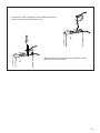
Securing the Lower Brackets
• Screw the brackets 7.1 to the front of the Hood Canopy using the screws 12a provided.
• Before tightening the Brackets completely, make all the adjustments to allow them to rest on
the lower base of the Cabinet Base to avoid deformation of the upper brackets 7.2 as shown
in the gure.

9
EN
2
26
12c
12a
7.1
12a
7.1
Fixing the Lower Brackets
• Screw the brackets 7.1 to the front of the Hood Canopy using the screws 12a provided.
• Before tightening the Brackets completely, make all the adjustments to allow them to rest on
the lower base of the worktop to avoid deformation of the upper brackets 7.2 as shown in the
figure.
• With the aid of a spirit level, set the Hood Canopy level vertically and fix it to the Lower
Surface using 2 screws 12c provided.
• Tighten the screws 12a completely.
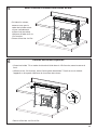
5
Leveling and Securing the Lower Brackets
• With the aid of a level,
set the Hood Canopy
level vertically and
secure it to the Lower
Surface using 2 screws
12c provided.
• Tighten the screws 12a
completely.
6
Securing the Squaring Brackets
• Screw the brackets 7.3 to the Hood Canopy using the screws 12b provided, without
tightening completely.
• Using the screws 12c provided, fasten the other part of the brackets 7.3 either to the side
walls of the unit or to the lower part of the cooktop.
EN
2
27
Fixing the Squaring Brackets
• Screw the brackets 7.3 to the Hood Canopy using the screws 12b provided, without
tightening completely.
• Using the screws 12c provided, fasten the other part of the brackets 7.3 either to the side
walls of the unit or to the lower part of the cooker top.
12b
7.3
12b
7.3
12c
• Tighten the screws 12c and 12b completely.
• Tighten the screws 12c and 12b completely.

10
7a
Internal Blower Installation
• Installation of the Internal Blower (1) at the front or rear must
be decided according to the position of the cooktop, making
sure that the plug is properly positioned.
• The Internal Blower can be rotated as shown in the
gure 2 for multiple venting directions..
• Screw the Internal Blower to the Hood
Canopy using the screws 12a and 12b
provided as shown in the gure.
3
3
3
CAUTION - To Reduce The Risk Of Fire And Electric Shock, Install This Down Draft Only With
Integral Blowers IBDD600-B Manufactured by Faber.

11
3
• Connect the Wire Connector from the Blower with the
correct connector on the Electric Unit.
• Secure the Wire Connector from the Blower at the
Electric Unit with 2 screws.
3

12
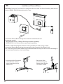
7b
Connect the Remote Blower wiring to the connector of the Electric Unit.
Accessories needed:
- Remote Blower model - RB900, RB1200 (purchased separately).
- WIREBOXSCLX for Remote Blower (purchased separately).
Attention: Install the Wiring Box with two screws (provided) on a at and dry surface.
Connect the Remote Blower wiring plug connector to the connector of the Electric Unit.
Run 2-wire plus ground power cable from the Remote Blower to wiring box on the Cover according to
local codes and ordinances. Use Listed ttings.
Installation of Remote Blower
CAUTION - To Reduce The Risk Of Fire And Electric Shock, Install This Down Draft Only With Remote
Blowers RB900, RB1200 Manufactured by Faber.
4x
3
• Connect the Wire Connector
from the Blower with the
correct connector on the
Electric Unit.
• Secure the Wire
Connector from the
Blower at the Electric
Unit with 2 screws.
3

13
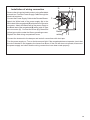
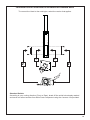
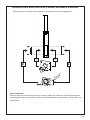
Installation of wiring connection
Remove the wiring electrical knockout using a at-blade
screwdriver. Feed the Power Supply Cable through the
electrical knockout.
Connect the Power Supply Cable to the Remote Blower.
Attach the White lead of the power supply (A) to the
White lead of the rangehood (D) with a twist-on type wire
connector. Attach the Black lead of the power supply to
the Black lead of the rangehood (B) with a twist-on type
wire connector (C). Connect the Green (E) (Green and
Yellow) ground wire under the Green grounding screws.
Replace the eld wiring compartment cover
Connect the ductwork to the damper and seal all connections with duct tape.
Turn the power supply on. Turn on the blower and light. If the rangehood does not operate, check that
the circuit breaker is not tripped or the house fuse blown. If the unit still does not operate, disconnect
the power supply and check that the wiring connections have been made properly.
Hood
wiring
A
E
E
D
B
C

14
8
EN
2
28
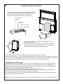
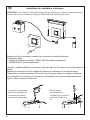
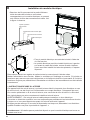
Fixing the Electric Unit
• Connect the wires coming out of the bottom
right part of the Hood Canopy to the
corresponding connector on the Electric
Unit, taking care not to make any wrong
connections.
• Fix the Electric Unit to the Hood Canopy
using the screws 12a provided.
• The position indicated in the figure is only
an option, as if necessary it may also be
fitted on the left of the Hood Canopy or
even left free on the base of the unit if there
are no structural or safety problems
involved.
Warning..: Do not install the product in such a way that the wiring box is in contact with the
floor.
• Connect the wires coming out of the bottom right part
of the Hood Canopy to the corresponding connector
on the Electric Unit, taking care not to make any
wrong connections. Check the picture below.
• Secure the Electric Unit to the Hood Canopy using the
screws 12a provided.
• The Electric Unit can be installed on the left or right of the
front of the hood canopy as shown above. It can also be
installed on the cabinet base if space allows.
EN
2
28
Fixing the Electric Unit
• Connect the wires coming out of the bottom
right part of the Hood Canopy to the
corresponding connector on the Electric
Unit, taking care not to make any wrong
connections.
• Fix the Electric Unit to the Hood Canopy
using the screws 12a provided.
• The position indicated in the figure is only
an option, as if necessary it may also be
fitted on the left of the Hood Canopy or
even left free on the base of the unit if there
are no structural or safety problems
involved.
Warning..: Do not install the product in such a way that the wiring box is in contact with the
floor.
"GROUNDING INSTRUCTIONS
This appliance must be grounded. In the event of an electrical short circuit, grounding reduces
the risk of electric shock by providing an escape wire for the electric current. This appliance is
equipped with a cord having a grounding wire with a grounding plug. The plug must be plugged
into an outlet that is properly installed and grounded.
WARNING - Improper grounding can result in a risk of electric shock.
Consult a qualied electrician if the grounding instructions are not completely understood, or if
doubt exists as to whether the appliance is properly grounded.
Do not use an extension cord. If the power supply cord is too short, have a qualied electrician
install an outlet near the appliance."
Warning..: Do not install the product in such a way that the electric unit is in contact with the oor.
Installation of Electrical Module
Connect the ductwork to the damper and seal all connections with duct tape.
Turn the power supply on. Turn on the blower and light. If the rangehood does not operate, check that
the circuit breaker is not tripped or the house fuse blown. If the unit still does not operate, disconnect
the power supply and check that the wiring connections have been made properly.
Power supply
Blower Connector
Command Flat
Connector
9 poles System
Connector

15
Connection the Air outlet with the
Accessories Remote
Motor
To connect the Hood to the outlet pipe, select the version that applies.
EN
2
29
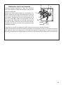
Connection to the Air outlet
To connect the Hood to the outlet pipe, select the ver-
sion that applies.
Standard Outlets
According to your decision (Right or Left), break the
outlet hole already marked and screw on Flange 2 using
the 4 screws 12a provided.
Optional Outlets
The Hood is fitted with three other possible outlets:
Right Side
Left Side
Bottom
According to your decision, unfasten the screws fixing
the cover and fit a connector, not provided, to the outlet
(the connector shown in the figure is merely an
example).
1 1
22
30mm
220mm
55mm
1
3/16
"
Standard Outlets
According to your venting direction (Front or Rear), break off the outlet hole already marked
and screw on callout number from Main Parts Component using the 4 screws 12a provided.
10"

16
EN
3
31
Warning..:
Handle
with care
Fitting the Front element
• Lift the mobile hood canopy
(see paragraph on Use) by just a
few centimeters.
• To stop movement, simply
press down on the mobile
canopy as it lifts up.
Warning: Never block the
sliding door when it is opening
or closing, except during the
operations required to fit the
frame.
• Remove the sponge guards
from the corners of the glass.
• Take the front Frame and insert
it from above, making sure that
its tabs insert into the slots
provided on the Hood and
sliding it to the left.
Warning..: All the tabs must
be inserted.
• Use a tool (hammer) to tap all
along the front Frame from
right to left until it is
completely flush.
A piece of wood or similar
element can be inserted
between the hammer and the
front Frame to prevent any
damage.
• Please refer to the paragraph on
Use for indications of how to
return the mobile canopy to the
Standard position.
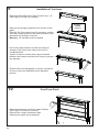
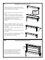
9
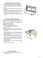
Installation of Top Frame
• Raise the downdraft to the Upper Position by a 1-2"
(See Page 15 for Use of Controls).
• Remove the sponge guards from the corners of the
glass.
• Take the Top Frame and insert it from above, making
sure that its tabs insert into the slots provided on the
downdraft and sliding it to the left.
Warning..: All the tabs must be inserted.
• Use a soft rubber mallet or similar tool to tap all
along the Top Frame from right to left until it is
completely ush.
A piece of wood or rubber block can be inserted
between the hammer and the front Frame to prevent
any damage.
• Please refer to the paragraph on Use for indications
of how to return the downdraft to the Standard
position.
10
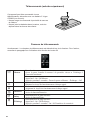
Front Cover Panel
EN
3
32
Surround Suction Panel
• Open the Hood Door (see
USE).
• Remove the 2 strips of adhesive
tape fastening the panel during
transport.
• Raise the telescopic part to the Upper Position
(See Page 15 for Use of Controls).
• Remove the 2 strips of adhesive tape
fastening the panel during transport.

17
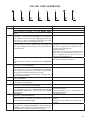
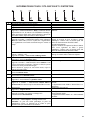
USE AND CARE INFORMATION
EN
3
33
USE
Control panel
Butto
n
Functio
n
o t t u b DEL
n
A
The button only works when the downdraft is open.
Press Briefly = Turns the Lights On/Off at maximum intensity.
Press and hold for 2 Seconds = Turns the Dimmer Lights
On/Off.
B Only works with the downdraft Open.
Press briefly = Activates/Deactivates Delay mode, causing auto-
matic shutdown of the Motor and the Lighting system from any
speed with a 15’ delay. It is disabled by pressing the same button
again, turning the motor off or closing the downdraft.
LED Button B+ Button for the set Speed are lit.
Works both with the downdraft Up and Down.
Press and hold for 2 Seconds = With the filter alarm triggered the
Filter Alarm is Reset. These indications are only visible when the
motor is turned off.
LED button ON:
Indicates the need to wash the metal grease filters.
The alarm is triggered after the Hood has been in
operation for 100 working hours.
Flashing LED button:
Indicates the need to change the activated charcoal
filters, and also to wash the metal grease filters. The
alarm is triggered after
the Hood has been in
operation for 200 working hours.
Works both with downdraft Up and Down with Motor + Lights =
Off.
Press and hold for 4 Seconds = Enables/disables the Keyboard
lock.
All the LED buttons flash twice. During the Lock
the LED buttons light up in sequence.
C Only works with the downdraft Up.
Press briefly = Activates speed four.
LED button ON.
Only works with the downdraft Up.
Press and hold for 2 seconds = Enables/Disables the
Intensive
speed. This speed is timed to run for 6 minutes. At the end of this
time the system will return to the speed set previously.
It is disabled by pressing the same button again, turning the motor
off or closing the downdraft.
Flashing LED button.
D Only works with the downdraft Up.
Activates speed three.
LED button ON.
E Only works with the downdraft Up
Activates/Deactivates speed two.
LED button ON.
F Only works with the downdraft Up.
Press briefly = Activates/Deactivates speed one.
LED button NO.
downdraft Up and Down
Press and hold for 2 Seconds = Enables/Disables the Activated
Charcoal Filter Alarm with the Motor turned off and no Filter
Alarm triggered.
LED button B flashes twice = Activated Charcoal
filter Alarm Activated.
LED button B flashes once = Activated Charcoal
filter Alarm Deactivate
d
.
G
downdraft Up
Press briefly = Turns the Motor off.
LED b
u
tton goes out.
downdraft Up and Down
Press and hold for 2 Seconds with Motor and Lights Off =
Enables/Disables the Remote control.
LED button
G
+ F flashes twice = Remote control
Enabled.
LED button G + F flashes once = Remote control
Disabled.
H downdraft Up = Lower the downdraft + Lights and Motor Off
downdraft Down = Upper the downdraft + Lights and Motor On.
Warning: If the downdraft remains partially open for any reason,
press the Button to complete the opening or closing cycle.
EN
3
33
USE
Control panel
Butto
n
Functio
n
o t t u b DEL
n
A
The button only works when the downdraft is open.
Press Briefly = Turns the Lights On/Off at maximum intensity.
Press and hold for 2 Seconds = Turns the Dimmer Lights
On/Off.
B Only works with the downdraft Open.
Press briefly = Activates/Deactivates Delay mode, causing auto-
matic shutdown of the Motor and the Lighting system from any
speed with a 15’ delay. It is disabled by pressing the same button
again, turning the motor off or closing the downdraft.
LED Button B+ Button for the set Speed are lit.
Works both with the downdraft Up and Down.
Press and hold for 2 Seconds = With the filter alarm triggered the
Filter Alarm is Reset. These indications are only visible when the
motor is turned off.
LED button ON:
Indicates the need to wash the metal grease filters.
The alarm is triggered after the Hood has been in
operation for 100 working hours.
Flashing LED button:
Indicates the need to change the activated charcoal
filters, and also to wash the metal grease filters. The
alarm is triggered after
the Hood has been in
operation for 200 working hours.
Works both with downdraft Up and Down with Motor + Lights =
Off.
Press and hold for 4 Seconds = Enables/disables the Keyboard
lock.
All the LED buttons flash twice. During the Lock
the LED buttons light up in sequence.
C Only works with the downdraft Up.
Press briefly = Activates speed four.
LED button ON.
Only works with the downdraft Up.
Press and hold for 2 seconds = Enables/Disables the Intensive
speed. This speed is timed to run for 6 minutes. At the end of this
time the system will return to the speed set previously.
It is disabled by pressing the same button again, turning the motor
off or closing the downdraft.
Flashing LED button.
D Only works with the downdraft Up.
Activates speed three.
LED button ON.
E Only works with the downdraft Up
Activates/Deactivates speed two.
LED button ON.
F Only works with the downdraft Up.
Press briefly = Activates/Deactivates speed one.
LED button NO.
downdraft Up and Down
Press and hold for 2 Seconds = Enables/Disables the Activated
Charcoal Filter Alarm with the Motor turned off and no Filter
Alarm triggered.
LED button B flashes twice = Activated Charcoal
filter Alarm Activated.
LED button B flashes once = Activated Charcoal
filter Alarm Deactivate
d
.
G
downdraft Up
Press briefly = Turns the Motor off.
LED b
u
tton goes out.
downdraft Up and Down
Press and hold for 2 Seconds with Motor and Lights Off =
Enables/Disables the Remote control.
LED button
G
+ F flashes twice = Remote control
Enabled.
LED button G + F flashes once = Remote control
Disabled.
H downdraft Up = Lower the downdraft + Lights and Motor Off
downdraft Down = Upper the downdraft + Lights and Motor On.
Warning: If the downdraft remains partially open for any reason,
press the Button to complete the opening or closing cycle.

18
RemoteControl(PurchasedSeparately)
This appliance can be commanded using a remote
control, powered by a CR2032 type 3 V battery (not
supplied).
• Do not place the remote control near heat sources.
• Do not discard the batteries with normal waste, they
must be put into the specic containers.
Remote Control Panel
Warning..: The remote control receiver is deactivated when rst supplied. To activate it, see the
paragraph Use Function of Button G.
EN
3
34
REMOTE CONTROL (OPTIONAL)
The appliance can be controlled using a remote control
powered by a 1.5 V carbon-zinc alkaline batteries of the
standard LR03-AAA type (not included).
• Do not place the remote control near to heat sources.
• Used batteries must be disposed of in the proper
manner.
Remote control panel
Warning..: The remote control receiver is deactivated when first supplied. To activate it, see the
paragraph Use Function of Button G.
Motor
downdraft Down:
Opens the downdraft, turns the motor on at speed one and turns the lights on at
maximum intensity.
downdraft Up:
Brief pressure: Motor On / Off.
Pressed for 2 Seconds: Closes the downdraft and Motor + Lights = Off.
Only with downdraftUp
:
Decreases the working speed each time it is pressed.
Only with downdraft Up
:
Increases the working speed each time it is pressed.
Intensive
Only with downdraft Up
:
Activates the Intensive function.
Delay
Only with downdraft Up
:
Activates the Delay function.
Light
Only with downdraft Up
:
Brief pressure: Lights On / Off.
Pressed for 2 Seconds: Dimmer lights On / Off.

19
LED LIGHTING UNIT
• LED lights must be replaced by Faber factory
authorized service.
Cleaning the Front Cover Panels
• Open the Front Cover Panel by pulling it at the top.
• Disconnect the panel from the hood canopy.
• The panel must never be washed in the dishwa-
sher.
• Clean the outside with a damp cloth and neutral
detergent.
• Clean the inside using a damp cloth and neutral
detergent; do not use wet cloths or sponges, or jets
of water; do not use abrasive substances.
• On completing the operation hook the panel and
close it.
CleaningtheMetalgreaselters
These can also be washed in the dishwasher, and
need to be cleaned whenever button B lights up or
at least once every 2 months use, or more frequently
if use is particularly intensive.
Resetting the alarm signal
• Turn the Lights and the Motor off.
• Press and hold button B for 2 seconds.
Cleaning the Filters
• Raise the downdraft to the Up position (see USE).
• Pull forward on the top edge of the Front Cover
to pull down.
• Remove the Filters one at a time, pushing them
towards the back of the unit and at the same time
pulling downward.
• Wash the Filters without bending them, and leave
them to dry completely before replacing. (If the
surface of the lter changes color as time goes by,
this will have absolutely no effect on the efciency
of the lter itself) .
• Replace, taking care to ensure that the handle
faces forwards.
• Close the Front Cover panel.

20
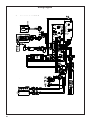
Wiring Diagram
991.0476.101 H90-322
D003071_03
991.0476.101 H90-322
D003071_03
La page est en cours de chargement...
La page est en cours de chargement...
La page est en cours de chargement...
La page est en cours de chargement...
La page est en cours de chargement...
La page est en cours de chargement...
La page est en cours de chargement...
La page est en cours de chargement...
La page est en cours de chargement...
La page est en cours de chargement...
La page est en cours de chargement...
La page est en cours de chargement...
La page est en cours de chargement...
La page est en cours de chargement...
La page est en cours de chargement...
La page est en cours de chargement...
La page est en cours de chargement...
La page est en cours de chargement...
La page est en cours de chargement...
La page est en cours de chargement...
La page est en cours de chargement...
La page est en cours de chargement...
La page est en cours de chargement...
La page est en cours de chargement...
-
 1
1
-
 2
2
-
 3
3
-
 4
4
-
 5
5
-
 6
6
-
 7
7
-
 8
8
-
 9
9
-
 10
10
-
 11
11
-
 12
12
-
 13
13
-
 14
14
-
 15
15
-
 16
16
-
 17
17
-
 18
18
-
 19
19
-
 20
20
-
 21
21
-
 22
22
-
 23
23
-
 24
24
-
 25
25
-
 26
26
-
 27
27
-
 28
28
-
 29
29
-
 30
30
-
 31
31
-
 32
32
-
 33
33
-
 34
34
-
 35
35
-
 36
36
-
 37
37
-
 38
38
-
 39
39
-
 40
40
-
 41
41
-
 42
42
-
 43
43
-
 44
44


Faber Scirocco Lux 30 BK Guide d'installation
- Catégorie
- Hottes
- Taper
- Guide d'installation
- Ce manuel convient également à
dans d''autres langues
Documents connexes
Autres documents
-
Forte BRAVO UL 507 Cooker Hood Manuel utilisateur
-
-
Gaggenau VL 200 120 *only compatible with recirculating blowers* Guide d'installation
-
Bertazzoni KT48XT Manuel utilisateur
-
Superiore HN241ANS Le manuel du propriétaire
-
 Franke Consumer Products FMY 367 Manuel utilisateur
-
 Franke Consumer Products FCH 367 Manuel utilisateur
-
 Franke Consumer Products FKU 368 TC W Manuel utilisateur
-
ROBLIN ZELIE 900 VERRE NOIR Le manuel du propriétaire
-
Gaggenau AA 490 711 Use & Care


