IMC Networks IE-MediaChassis/1 Mode d'emploi
- Taper
- Mode d'emploi

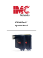
IE-MediaChassis/1
Operation Manual

ii
FCC Radio Frequency Interference Statement
This equipment has been tested and found to comply with the limits for a Class B computing device, pursuant to Part 15 of the FCC Rules.
These limits are designed to provide reasonable protection against harmful interference when the equipment is operated in a commercial
environment. This equipment generates, uses and can radiate radio frequency energy and, if not installed and used in accordance with the
instruction manual, may cause harmful interference to radio communications. Operation of this equipment in a residential area is likely to
cause harmful interference in which the user will be required to correct the interference at his own expense.
Any changes or modifications not expressly approved by the manufacturer could void the user’s authority to operate the equipment.
The use of non-shielded I/O cables may not guarantee compliance with FCC RFI limits. This digital apparatus does not exceed the Class B
limits for radio noise emission from digital apparatus set out in the Radio Interference Regulation of the Canadian Department of
Communications.
Le présent appareil numérique n’émet pas de bruits radioélectriques dépassant les limites applicables aux appareils numériques de classe B
prescrites dans le Règlement sur le brouillage radioélectrique publié par le ministère des Communications du Canada.
Warranty
IMC Networks warrants to the original end-user purchaser that this product, EXCLUSIVE OF SOFTWARE, shall be free
from defects in materials and workmanship under normal and proper use in accordance with IMC Networks' instructions
and directions for a period of six (6) years after the original date of purchase. This warranty is subject to the limitations set
forth below.
At its option, IMC Networks will repair or replace at no charge the product which proves to be defective within such
warranty period. This limited warranty shall not apply if the IMC Networks product has been damaged by unreasonable
use, accident, negligence, service or modification by anyone other than an authorized IMC Networks Service Technician
or by any other causes unrelated to defective materials or workmanship. Any replaced or repaired products or parts carry
a ninety (90) day warranty or the remainder of the initial warranty period, whichever is longer.
To receive in-warranty service, the defective product must be received at IMC Networks no later than the end of the
warranty period. The product must be accompanied by proof of purchase, satisfactory to IMC Networks, denoting
product serial number and purchase date, a written description of the defect and a Return Merchandise Authorization
(RMA) number issued by IMC Networks. No products will be accepted by IMC Networks which do not have an RMA
number. For an RMA number, contact IMC Networks at PHONE: (800) 624-1070 (in the U.S and Canada) or (949) 465-
3000 or FAX: (949) 465-3020. The end-user shall return the defective product to IMC Networks, freight, customs and
handling charges prepaid. End-user agrees to accept all liability for loss of or damages to the returned product during
shipment. IMC Networks shall repair or replace the returned product, at its option, and return the repaired or new
product to the end-user, freight prepaid, via method to be determined by IMC Networks. IMC Networks shall not be
liable for any costs of procurement of substitute goods, loss of profits, or any incidental, consequential, and/or special
damages of any kind resulting from a breach of any applicable express or implied warranty, breach of any obligation
arising from breach of warranty, or otherwise with respect to the manufacture and sale of any IMC Networks product,
whether or not IMC Networks has been advised of the possibility of such loss or damage.
EXCEPT FOR THE EXPRESS WARRANTY SET FORTH ABOVE, IMC NETWORKS MAKES NO OTHER WARRANTIES,
WHETHER EXPRESS OR IMPLIED, WITH RESPECT TO THIS IMC NETWORKS PRODUCT, INCLUDING WITHOUT
LIMITATION ANY SOFTWARE ASSOCIATED OR INCLUDED. IMC NETWORKS SHALL DISREGARD AND NOT BE
BOUND BY ANY REPRESENTATIONS OR WARRANTIES MADE BY ANY OTHER PERSON, INCLUDING EMPLOYEES,
DISTRIBUTORS, RESELLERS OR DEALERS OF IMC NETWORKS, WHICH ARE
INCONSISTENT WITH THE WARRANTY SET FORTH ABOVE. ALL IMPLIED WARRANTIES INCLUDING THOSE OF
MERCHANTABILITY AND FITNESS FOR A PARTICULAR PURPOSE ARE HEREBY LIMITED TO THE DURATION OF THE
EXPRESS WARRANTY STATED ABOVE.
Every reasonable effort has been made to ensure that IMC Networks product manuals and promotional materials
accurately describe IMC Networks product specifications and capabilities at the time of publication. However, because of
ongoing improvements and updating of IMC Networks products, IMC Networks cannot guarantee the accuracy of printed
materials after the date of publication and disclaims liability for changes, errors or omissions.

iii
Table of Contents
FCC Radio Frequency Interference Statement ...........................................................ii
Warranty...................................................................................................................ii
About the IE-MediaChassis/1.....................................................................................1
Configuring and Installing Modules............................................................................1
Installing the IE-MediaChassis/1.................................................................................1
Powering the IE-MediaChassis/1................................................................................2
DC Terminal Block Wiring Instructions......................................................................3
Cascading DC Power ................................................................................................4
DC Power Supply Precautions...................................................................................5
Specifications ............................................................................................................6
Electrostatic Discharge Precautions............................................................................7
Safety Certifications...................................................................................................8

1
About the IE-MediaChassis/1
The Industrial Ethernet IE-MediaChassis/1 is a compact and modular, single-slot table-
top unit that hosts a variety of IMC Networks iMcV-Modules. The IE-MediaChassis/1
has two power options: a 4-terminal DC power block, and a country-specific external
AC power adapter. In addition, IE-MediaChassis/1 also includes an extended voltage
range; an extended operating temperature; and DIN clips for mounting the enclosure
on a DIN rail. Deploy these standalone chassis at the customer premises (CPE) or
each access point.
Configuring and Installing Modules
To install a module (any iMcV series module except those that are double- wide),
slide the module into the chassis until the module is firmly seated in the backplane.
Secure the module to the chassis by tightening the captive screw.
NOTE
Please refer to the installation guide online for the module for configuration
and operation information.
The power source in this chassis is not isolated, and cannot support positive
reference ground systems typically used in Telco environments. The
MediaChassis/2-DC and the iMediachassis/6-DC are suitable alternates.
Installing the IE-MediaChassis/1
IE-MediaChassis/1 installs virtually anywhere: as a standalone, table-top device, on a
DIN rail, or Wallmounted. As a table-top unit, install the IE-MediaChassis/1 by
placing it on a flat surface. Make sure to leave adequate space on top of the unit to
accommodate cooling. Attach the network cables between the module and other
devices that will be interconnected, and then plug the unit into a reliable, filtered
power source.
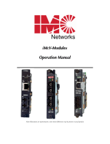
Wallmount Bracket Installation
Wallmount Brackets, an optional accessory available through IMC Networks (Part
number 895-39229) allow the IE-MediaChassis/1 to be Wallmounted. Refer to DIN
Rail Mounting diagram for this mounting option.

2
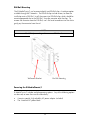
DIN Rail Mounting
The IE-MediaChassis/1 can be mounted with two DIN Rail clips, a hardware option
available through IMC Networks. The DIN Rail clips include screws, to allow the
installation onto a DIN Rail. Install the screws into DIN Rail clips, which should be
mounted perpendicular to the DIN Rail. Snap the converter onto the clips. To
remove the converter from the DIN Rail, use a flat-head screwdriver into the slot to
gently pry the converter from the rail.
NOTE
The DIN clips are designed for use on a DIN-35 rail.
Wallmount Bracket Din Rail Mounting
Powering the IE-MediaChassis/1
IE-MediaChassis/1 includes multiple powering options. Any of the following options
can be used, or more than one for redundancy:
•
A country-specific, high-reliability AC power adapter (included)
•
The 4-terminal DC power block

3
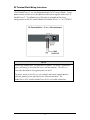
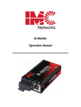
DC Terminal Block Wiring Instructions
The IE-MediaChassis/1 can also be powered with the DC terminal block. From a
power source, connect to any one positive and any one negative terminal on IE-
MediaChassis/1. The following chart illustrates an example of the wiring
configurations for the DC terminal block of IE-MediaChassis/1 (±7 to ±50 VDC).
NOTE
When using stranded wire, the leads must be tinned. The chassis is protected
against mis-wiring; if mis-wired the chassis will not function. The chassis is
internally connected to the negative power terminal.
The power source in this chassis is not isolated, and cannot support positive
reference ground systems typically used in Telco environments. The
MediaChassis/2-DC and the iMediaChassis/6-DC are suitable alternatives.

4
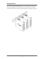
Cascading DC Power
When installing multiple IE-MediaChassis/1 units on a DIN rail, use one DC input
source then cascade from one DC block to the next, until reaching the maximum
current available. Make sure to connect positive to positive and negative to negative.

5
DC Power Supply Precautions
The following precautions should be observed when installing chassis with DC power
supplies.
1.
Check nameplate ratings to assure there is no overloading of supply circuits that
could have an effect on overcurrent protection and supply wiring.
2.
When installing DC equipment, it must be installed only per the following
conditions:
a.
Connect the equipment to a
±
7 to
±
50 VDC supply source that is
electrically isolated form the alternating current source. The
±
7 to
±
50 VDC
source is to be connected to a SELV source.
b.
Input wiring to terminal block must be routed and secured in such a
manner that it is protected from damage and stress. Do not route wiring
past sharp edges or moving parts.
c.
A readily accessible disconnect device, with a 3 mm minimum contact gap,
shall be incorporated in the fixed wiring.
3.
Grounding: reliable grounding of this equipment must be maintained. Particular
attention should be given to supply connections when connecting to power
strips, rather than direct connections to the branch circuit.

6
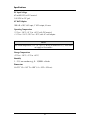
Specifications
DC Input Voltage
±
7 to
±
50 VDC on DC terminal
5-20 VDC on DC jack
AC Wall Adapter
100-240 ±10% VAC input, 5 VDC output, 2A max.
Operating Temperature
-13°F to +185°F (-25°C to +85°C) with DC terminal
+14°F to +122°F (-10°C to +50°C) with AC wall adapter
NOTE
The stated temperature (-25C° to +85°C) is for the IE-MediaChassis/1, and it does
not apply to the modules.
Storage Temperature
-49°F to +185°F (-45°C to +85°C)
Humidity
5 – 95% (non-condensing); 0 – 10,000 ft. altitude
Dimensions
H=0.91” W=4.30” D=4.00” (2.3 x 10.9 x 10.2 cm)

7
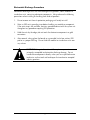
Electrostatic Discharge Precautions
Electrostatic discharge (ESD) can cause damage to any product, add-in modules or
stand alone units, containing electronic components. Always observe the following
precautions when installing or handling these kinds of products
1.
Do not remove unit from its protective packaging until ready to install.
2.
Wear an ESD wrist grounding strap before handling any module or component.
If the wrist strap is not available, maintain grounded contact with the system unit
throughout any procedure requiring ESD protection.
3.
Hold the units by the edges; do not touch the electronic components or gold
connectors.
4.
After removal, always place the boards on a grounded, static-free surface, ESD
pad or in a proper ESD bag. Do not slide the modules or stand alone units over
any surface.
WARNING!
Integrated circuits and fiber optic components are
extremely susceptible to electrostatic discharge damage. Do not
handle these components directly unless you are a qualified service
technician and use tools and techniques that conform to accepted
industry practices.

8
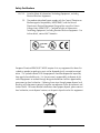
Safety Certifications
UL/CUL: Listed to Safety of Information Technology Equipment, including
Electrical Business Equipment.
CE: The products described herein comply with the Council Directive on
Electromagnetic Compatibility (2004/108/EC) and the Council
Directive on Electrical Equipment Designed for use within Certain
Voltage Limits (2006/95/EC). Certified to Safety of Information
Technology Equipment, Including Electrical Business Equipment. For
further details, contact IMC Networks.
European Directive 2002/96/EC (WEEE) requires that any equipment that bears this
symbol on product or packaging must not be disposed of with unsorted municipal
waste. This symbol indicates that the equipment should be disposed of separately
from regular household waste. It is the consumer’s responsibility to dispose of this
and all equipment so marked through designated collection facilities appointed by
government or local authorities. Following these steps through proper disposal and
recycling will help prevent potential negative consequences to the environment and
human health. For more detailed information about proper disposal, please contact
local authorities, waste disposal services, or the point of purchase for this equipment.

19772 Pauling • Foothill Ranch, CA 92610-2611 USA
TEL: (949) 465-3000 • FAX: (949) 465-3020
www.imcnetworks.com
© 2012 IMC Networks. All rights reserved
The information in this document is subject to change without notice. IMC Networks assumes no responsibility for any
errors that may appear in this document. IE-MediaChassis/1 is a trademark of IMC Networks. Other brands or product
names may be trademarks and are the property of their respective companies.
Document Number 50-80101-00 A4 March 2012
-
 1
1
-
 2
2
-
 3
3
-
 4
4
-
 5
5
-
 6
6
-
 7
7
-
 8
8
-
 9
9
-
 10
10
-
 11
11
-
 12
12


IMC Networks IE-MediaChassis/1 Mode d'emploi
- Taper
- Mode d'emploi
dans d''autres langues
Documents connexes
-
 IMC Networks MediaChassis Series Mode d'emploi
-
 IMC Networks MediaChassis/I-AC Guide d'installation
-
 IMC Networks iMcV-S2SM/1250 Manuel utilisateur
-
 IMC Networks IE-MiniMc Mode d'emploi
-
 IMC Networks IE-PowerTray/18 Mode d'emploi
-
 IMC Networks IE-Giga-MiniMc Mode d'emploi
-
 IMC Networks Giga-MiniMc LFPT Mode d'emploi
-
 IMC Networks MiniMc-Gigabit Mode d'emploi
-
 IMC Networks Giga-MiniMc Mode d'emploi
-
 IMC Networks 856-10728 Manuel utilisateur


