
OCD6-1999
OCD6-1999
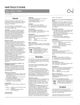
• English
• Deutsch
• Français
• Suomi
• Polski
• Česky
INSTRUCTIONS
67471B 04/16 (HKT)
© 2016 OJ Electronics A/S
GREEN COMFORT
Maximum comfort with low energy consumption
• Svenska
• Nederlands
• Lietuvių k.
• Italiano
• Español
• Norsk
• Português

© 2016 OJ Electronics A/S
2
© 2016 OJ Electronics A/S
ILLUSTRATIONS
Pages ....................................................................................3
INSTRUCTIONS
English .................................................................................. 7
Deutsch .............................................................................. 12
Français .............................................................................. 17
Suomi ................................................................................. 22
Polski .................................................................................. 27
Česky .................................................................................. 32
Svenska .............................................................................. 37
Nederlands ......................................................................... 42
Lietuvių k. ........................................................................... 47
Italiano ................................................................................ 52
Español ............................................................................... 57
Norsk .................................................................................. 62
Português ........................................................................... 67
Fig. 1
Fig. 2

3
© 2016 OJ Electronics A/S
OCD6-1999
© 2016 OJ Electronics A/S
ILLUSTRATIONS
Pages ....................................................................................3
INSTRUCTIONS
English .................................................................................. 7
Deutsch .............................................................................. 12
Français .............................................................................. 17
Suomi ................................................................................. 22
Polski .................................................................................. 27
Česky .................................................................................. 32
Svenska .............................................................................. 37
Nederlands ......................................................................... 42
Lietuvių k. ........................................................................... 47
Italiano ................................................................................ 52
Español ............................................................................... 57
Norsk .................................................................................. 62
Português ........................................................................... 67
BR1024A02
© 2015 OJ Electronics A/S
Fig. 1
Fig. 2
BR1024A01
© 2015 OJ Electronics A/S
BR1024A01BR1024A02

4
© 2016 OJ Electronics A/S © 2016 OJ Electronics A/S
BR1024A04
OCD6-1999
BR1024A03
© 2015 OJ Electronics A/S
BR1024A04
© 2015 OJ Electronics A/S
3
2
1
3
4
BR1024A03
Fig. 3
Fig. 4

© 2016 OJ Electronics A/S
5
© 2016 OJ Electronics A/S
OCD6-1999
OCD6-1999
BR1024A06
© 2015 OJ Electronics A/S
654321
N
L
Fig. 5
BR1024A06
BR1024A07
© 2015 OJ Electronics A/S
BR1024A07
Fig. 6

© 2016 OJ Electronics A/S
6 © 2016 OJ Electronics A/S
OCD6-1999
BR1017A08
BR1024A08
© 2015 OJ Electronics A/S
Fig. 7
BR1017A17a
Fig. 9
Udarbejdet af: Udarbejdet d.: 29.05.2015 Side 1 af 1
©
2015
OJ ELECTRONICS A/S • STENAGER 13B • DK-6400 SØNDERBORG
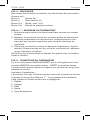
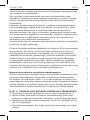
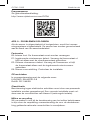
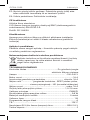
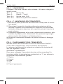
NTC 12kΩ @ 25°Celsius
°Celsius
°Fahrenheit
Ohm (Ω)
-10°C 14°F 55076Ω
0°C 32°F 34603Ω
10°C 50°F 22284Ω
20°C 68°F 14675Ω
30°C 86°F 9860Ω
BR1024A09
Fig. 8
BR1024A09
© 2015 OJ Electronics A/S
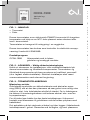
1
2
21.5º
Manual
Other Mode
I ON
O OFF
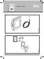
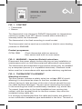
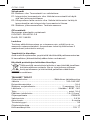
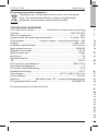
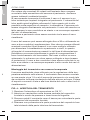
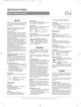
FIG. 1 - CONTENT
• Thermostat
• Sensor
The thermostat is an electronic PWM/PI thermostat for temperature
control by means of an NTC sensor located either externally or
internally within the thermostat.
The thermostat is for flush mounting in a wall socket.
This thermostat can be used as a controller for electric room heating
pursuant to EN50559.
Product programme
OCD6-1999 Clock-thermostat with two sensors:
floor sensor and built-in room sensor.
FIG. 2 - WARNING – Important Safety Instructions
Disconnect the power supply before carrying out any installation or
maintenance work on this thermostat and associated components.
The thermostat and associated components should only be installed
by a competent person (i.e. a qualified electrician). Electrical instal-
lation must be in accordance with appropriate statutory regulations.
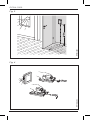
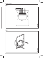
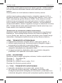
FIG. 3 - THERMOSTAT PLACEMENT
Mounting of sensor
The floor sensor contains a safety extra-low voltage (SELV) circuit,
allowing it to be placed as close to the floor surface as possible
without having to take account of the risk of shock should the sen-
sor cable become damaged. The two wires connecting the sensor
to the mounting box must be additionally insulated, e.g. shrink flex.
To prevent loose wires in the fixed installation from coming into
contact with the terminal block for the floor sensor, they must be
restrained using cable ties.
It is strongly recommended that the cable and sensor are placed in
a non-conductive installation pipe embedded in the floor. The end of

7
© 2016 OJ Electronics A/S
OCD6-1999
© 2016 OJ Electronics A/S
OCD6-1999
FIG. 1 - CONTENT
• Thermostat
• Sensor
The thermostat is an electronic PWM/PI thermostat for temperature
control by means of an NTC sensor located either externally or
internally within the thermostat.
The thermostat is for flush mounting in a wall socket.
This thermostat can be used as a controller for electric room heating
pursuant to EN50559.
Product programme
OCD6-1999 Clock-thermostat with two sensors:
floor sensor and built-in room sensor.
FIG. 2 - WARNING – Important Safety Instructions
Disconnect the power supply before carrying out any installation or
maintenance work on this thermostat and associated components.
The thermostat and associated components should only be installed
by a competent person (i.e. a qualified electrician). Electrical instal-
lation must be in accordance with appropriate statutory regulations.
FIG. 3 - THERMOSTAT PLACEMENT
Mounting of sensor
The floor sensor contains a safety extra-low voltage (SELV) circuit,
allowing it to be placed as close to the floor surface as possible
without having to take account of the risk of shock should the sen-
sor cable become damaged. The two wires connecting the sensor
to the mounting box must be additionally insulated, e.g. shrink flex.
To prevent loose wires in the fixed installation from coming into
contact with the terminal block for the floor sensor, they must be
restrained using cable ties.
It is strongly recommended that the cable and sensor are placed in
a non-conductive installation pipe embedded in the floor. The end of
Instruction
English

8
© 2016 OJ Electronics A/S © 2016 OJ Electronics A/S
the pipe must be sealed and the pipe placed as high as possible in
the concrete layer. Alternatively, the sensor can be embedded di-
rectly in the floor. The sensor cable must be led through a separate
conduit or segregated from power cables.
The floor sensor must be centred between loops of heating cable.
The sensor cable may be extended up to 30m by means of a
separate two-core cable. Two vacant wires in a multi-core cable
used, for example, to supply current to the floor heating cable must
not be used. The switching peaks of such current supply lines may
create interference signals that prevent optimum thermostat func-
tion. If a shielded cable is used, the shield must not be connected
to earth (PE). The two-core cable must be placed in a separate
pipe or segregated from power cables in some other way.
Mounting of thermostat with built-in sensor
The room sensor is used for comfort temperature regulation in
rooms. The thermostat should be mounted on the wall approx.
1.5 m above the floor in such a way as to allow free air circulation
around it. Draughts and direct sunlight or other heat sources must
be avoided.
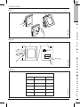
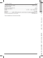
FIG. 4 - OPENING THE THERMOSTAT
1. Slide the power button down to O “0”.
2. Insert a small screwdriver into the central slot of the front cover
to press and hold the catch.
3. Then push the handle of the screwdriver downwards to release
the rear part from the front cover.
4. Carefully pull the rear part away from the front cover, starting
with the lower part of the thermostat.
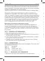
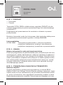
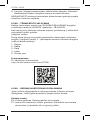
FIG. 5 - CONNECTIONS
Connect the wires in accordance with the diagram. The wires must
be connected as follows:
Term. 1: Neutral (N)
Term. 2: Live (L)
Term. 3-4: Output, max. 16 A
Term. 5-6: External floor sensor
FIG. 6 + 7 - MOUNTING THE THERMOSTAT
1. Mount the rear part of the thermostat in the wall socket.
OCD6-1999 English
2. Refit the front cover to the rear part of the thermostat.
Carefully press the cover onto the thermostat, starting with the
upper part of the cover before fitting the lower part of the cover.
3. Click the cover into place by applying light, even pressure.
Warning! Do not apply pressure to the corners of the display
cover or to the display itself.
DO NOT open the thermostat by releasing the four fixing clips on
the back.
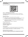
FIG. 8 - OPERATING THE THERMOSTAT
There is an ON/OFF switch on the left side of the thermostat: up is
ON - down is OFF.
The resistive touchscreen requires a soft tap with your fingertip to
register the touch.
Installer Wizard:
The first time the thermostat is connected, push the power slide
button to On “I” The Installer Wizard on the touchscreen will guide
you through the set up of:
1. Region
2. Language
3. Date
4. Time
5. Floor Type
Programming
See user manual.
http://www.ojelectronics.com/OCD6
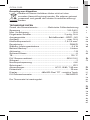
FIG. 9 - TROUBLESHOOTING
If the sensor is disconnected or short-circuited, the heating system
is switched o. The sensor can be checked against the resistance
table.
OCD6-1999 English

© 2016 OJ Electronics A/S
9
© 2016 OJ Electronics A/S
the pipe must be sealed and the pipe placed as high as possible in
the concrete layer. Alternatively, the sensor can be embedded di-
rectly in the floor. The sensor cable must be led through a separate
conduit or segregated from power cables.
The floor sensor must be centred between loops of heating cable.
The sensor cable may be extended up to 30m by means of a
separate two-core cable. Two vacant wires in a multi-core cable
used, for example, to supply current to the floor heating cable must
not be used. The switching peaks of such current supply lines may
create interference signals that prevent optimum thermostat func-
tion. If a shielded cable is used, the shield must not be connected
to earth (PE). The two-core cable must be placed in a separate
pipe or segregated from power cables in some other way.
Mounting of thermostat with built-in sensor
The room sensor is used for comfort temperature regulation in
rooms. The thermostat should be mounted on the wall approx.
1.5 m above the floor in such a way as to allow free air circulation
around it. Draughts and direct sunlight or other heat sources must
be avoided.
FIG. 4 - OPENING THE THERMOSTAT
1. Slide the power button down to O “0”.
2. Insert a small screwdriver into the central slot of the front cover
to press and hold the catch.
3. Then push the handle of the screwdriver downwards to release
the rear part from the front cover.
4. Carefully pull the rear part away from the front cover, starting
with the lower part of the thermostat.
FIG. 5 - CONNECTIONS
Connect the wires in accordance with the diagram. The wires must
be connected as follows:
Term. 1: Neutral (N)
Term. 2: Live (L)
Term. 3-4: Output, max. 16 A
Term. 5-6: External floor sensor
FIG. 6 + 7 - MOUNTING THE THERMOSTAT
1. Mount the rear part of the thermostat in the wall socket.
2. Refit the front cover to the rear part of the thermostat.
Carefully press the cover onto the thermostat, starting with the
upper part of the cover before fitting the lower part of the cover.
3. Click the cover into place by applying light, even pressure.
Warning! Do not apply pressure to the corners of the display
cover or to the display itself.
DO NOT open the thermostat by releasing the four fixing clips on
the back.
FIG. 8 - OPERATING THE THERMOSTAT
There is an ON/OFF switch on the left side of the thermostat: up is
ON - down is OFF.
The resistive touchscreen requires a soft tap with your fingertip to
register the touch.
Installer Wizard:
The first time the thermostat is connected, push the power slide
button to On “I” The Installer Wizard on the touchscreen will guide
you through the set up of:
1. Region
2. Language
3. Date
4. Time
5. Floor Type
Programming
See user manual.
http://www.ojelectronics.com/OCD6
FIG. 9 - TROUBLESHOOTING
If the sensor is disconnected or short-circuited, the heating system
is switched o. The sensor can be checked against the resistance
table.
OCD6-1999 English

10
© 2016 OJ Electronics A/S © 2016 OJ Electronics A/S
Error codes
E0: Internal fault. The thermostat must be replaced.
E1: Built-in room sensor fault. Replace the thermostat or continue
to use it with the floor sensor only.
E2: External floor sensor fault. Replace the floor sensor or continue
to use the thermostat with the built-in room sensor only.
E5: Internal overheating. Inspect the installation.
CE marking
According to the following standard:
LVD/EMC: EN 60730-2-9
RoHS: 2011/65/EU
Classification
Protection from electric shock must be assured by appropriate
installation. Appropriate installation must meet the requirements of
Class II (reinforced insulation).
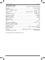
Environment and recycling
Please help us to protect the environment by disposing of the
packaging in accordance with national regulations for waste
processing.
Recycling of obsolete appliances
Appliances with this label must not be disposed of with
general household waste. They must be collected
separately and disposed of in compliance with local
regulations.
OCD6-1999 English
OCD6-1999 English

© 2016 OJ Electronics A/S
11
© 2016 OJ Electronics A/S
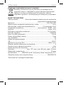
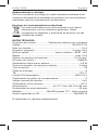
TECHNICAL DATA
Purpose of control....................................Electric underfloor heating
Voltage ........................................................................ 100-240 VAC
Max. pre-fuse .............................................................................16 A
Built-in circuit breaker .................................................. 2-pole, 16 A
Output relay ........................................... make contact - SPST - NO
Output .............................................................................. max. 16 A
Terminal wire size .......................................................... 1.5-2.5 mm
2
Control principle .................................................................. PWM/PI
Standby power ........................................................................ 0.5 W
Battery backup ..................................................................... 5 years
Action type .................................................................................. 1.B
Software class .................................................................................A
TB ............................................................................................ 125°C
ELV limits realized ............................................................. SELV 24 V
Pollution degree rating.....................................................................2
Rated impulse voltage ............................................................... 4 kV
Enclosure rating ........................................................................ IP 21
Dimensions .................................................. H/121, W/80, D/43 mm
Build-in depth ........................................................................ 23 mm
Display ...................................... 480x320 pixel TFT - resistive touch
EU registered design .................................................... DM/082270
The thermostat is maintenance free.
OCD6-1999 English

© 2016 OJ Electronics A/S © 2016 OJ Electronics A/S
12
OCD6-1999
Anleitung
Deutsch
ABB. 1 – LIEFERUMFANG
• Thermostat
• Fühler
Der Thermostat ist ein elektronischer PBM/PI-Thermostat zur Tem-
peraturregelung mittels extern angebrachtem oder im Thermostat
eingebauten NTC-Fühler.
Der Thermostat ist für Unterputzmontage in einer Wanddose
vorgesehen.
Dieser Thermostat kann zur Steuerung von elektrischer Raumhei-
zung gemäß EN50559 verwendet werden.
Produktprogramm
OCD6-1999 Uhr-Thermostat mit zwei Fühlern:
Bodenfühler und eingebauter Raumfühler.
ABB. 2 – WARNHINWEIS – Wichtige Sicherheitsanweisungen.
Vor der Ausführung von Installations- oder Instandhaltungsar-
beiten an diesem Thermostat und zugehörigen Komponenten ist
die Spannungsversorgung zu unterbrechen. Der Thermostat und
zugehörige Komponenten dürfen nur von einer sachkundigen
Person (d. h. einem qualifizierten Elektriker) installiert werden.
Die Elektroinstallation muss den entsprechenden gesetzlichen
Vorschriften entsprechen.
ABB. 3 – THERMOSTAT-PLATZIERUNG
Montage des Fühlers
Der Bodenfühler ist mit einem Kleinspannungs-Sicherheitskreis
(SELV) ausgestattet, womit eine Anbringung möglichst nahe an
der Fußbodenoberfläche ohne Risiko von Stromschlägen durch
ein eventuell schadhaft werdendes Fühlerkabel erfolgen kann. Die
beiden Leiter für den Anschluss des Fühlers im Klemmenkasten
müssen zusätzlich isoliert werden, z. B. mit Schrumpfschlauch.
Um einem Kontakt der Klemmenleiste des Bodenfühlers mit losen
Drähten der vorhandenen Installation vorzubeugen, müssen diese
mit Kabelbindern festgemacht werden.
Es empfiehlt sich, Kabel und Fühler in einem im Boden eingelas-
senen, nicht leitenden Installationsrohr anzubringen. Mit ver-
schlossenem Rohrende sollte das Rohr so hoch wie möglich in der
Estrichschicht eingebettet sein. Alternativ kann der Fühler direkt im
Boden eingebettet werden. Das Fühlerkabel ist in einem separaten
Rohr oder getrennt von Leistungskabeln zu verlegen.
Der Bodenfühler muss zwischen den Heizkabelschleifen zentriert
werden.
Das Fühlerkabel kann mit einem separaten Zweileiterkabel bis zu
30 m verlängert werden. Freie Leiter in einem z. B. das Boden-
heizkabel mit Strom versorgenden Mehrleiterkabel dürfen nicht
verwendet werden. Die Schaltspitzen einer derartigen Stromversor-
gung können Interferenzen auslösen die eine optimale Thermo-
statfunktion behindern. Wird ein abgeschirmtes Kabel verwendet,
darf die Abschirmung nicht geerdet werden. Das Zweileiterkabel
ist in einem separaten Rohr oder getrennt von Leistungskabeln zu
verlegen.
Montage eines Thermostats mit eingebautem Fühler
Der Raumfühler wird zur Regelung der Komforttemperatur in
Räumen eingesetzt. Der Thermostat ist auf der Wand ca. 1,5 m
über dem Boden und freie Luftzirkulation um ihn gestattend zu
montieren. Zugluft und direkte Sonneneinstrahlung oder andere
Wärmequellen müssen vermieden werden.
ABB. 4 – ÖFFNEN DES THERMOSTAT GEHÄUSES
1. Den Schiebeschalter nach unten in Position Aus „0“ schieben.
2. Einen kleinen Schraubendreher in den mittleren Schlitz der
Frontabdeckung einsetzen und gegen die Raste drücken.
3. Dann den Handgri des Schraubendrehers nach unten drücken,
um die Frontabdeckung vom Gehäuse zu lösen.
4. Beginnend am unteren Teil des Thermostats vorsichtig das
Gehäuse von der Frontabdeckung entfernen.
OCD6-1999 Deutsch

© 2016 OJ Electronics A/S
13
© 2016 OJ Electronics A/S
Um einem Kontakt der Klemmenleiste des Bodenfühlers mit losen
Drähten der vorhandenen Installation vorzubeugen, müssen diese
mit Kabelbindern festgemacht werden.
Es empfiehlt sich, Kabel und Fühler in einem im Boden eingelas-
senen, nicht leitenden Installationsrohr anzubringen. Mit ver-
schlossenem Rohrende sollte das Rohr so hoch wie möglich in der
Estrichschicht eingebettet sein. Alternativ kann der Fühler direkt im
Boden eingebettet werden. Das Fühlerkabel ist in einem separaten
Rohr oder getrennt von Leistungskabeln zu verlegen.
Der Bodenfühler muss zwischen den Heizkabelschleifen zentriert
werden.
Das Fühlerkabel kann mit einem separaten Zweileiterkabel bis zu
30 m verlängert werden. Freie Leiter in einem z. B. das Boden-
heizkabel mit Strom versorgenden Mehrleiterkabel dürfen nicht
verwendet werden. Die Schaltspitzen einer derartigen Stromversor-
gung können Interferenzen auslösen die eine optimale Thermo-
statfunktion behindern. Wird ein abgeschirmtes Kabel verwendet,
darf die Abschirmung nicht geerdet werden. Das Zweileiterkabel
ist in einem separaten Rohr oder getrennt von Leistungskabeln zu
verlegen.
Montage eines Thermostats mit eingebautem Fühler
Der Raumfühler wird zur Regelung der Komforttemperatur in
Räumen eingesetzt. Der Thermostat ist auf der Wand ca. 1,5 m
über dem Boden und freie Luftzirkulation um ihn gestattend zu
montieren. Zugluft und direkte Sonneneinstrahlung oder andere
Wärmequellen müssen vermieden werden.
ABB. 4 – ÖFFNEN DES THERMOSTAT GEHÄUSES
1. Den Schiebeschalter nach unten in Position Aus „0“ schieben.
2. Einen kleinen Schraubendreher in den mittleren Schlitz der
Frontabdeckung einsetzen und gegen die Raste drücken.
3. Dann den Handgri des Schraubendrehers nach unten drücken,
um die Frontabdeckung vom Gehäuse zu lösen.
4. Beginnend am unteren Teil des Thermostats vorsichtig das
Gehäuse von der Frontabdeckung entfernen.
OCD6-1999 Deutsch

14
© 2016 OJ Electronics A/S © 2016 OJ Electronics A/S
ABB. 5 – ANSCHLÜSSE
Die Leiter gemäß Schaltplan anschließen. Die Leiterdrähte müssen
wie folgt angeschlossen werden:
Klemme 1: Nullleiter (N)
Klemme 2: Phase (L)
Klemme 3-4: Ausgang, max. 16A
Klemme 5-6: Externer Bodenfühler
ABB. 6 + 7 – MONTAGE DES THERMOSTATS
1. Das Gehäuse des Thermostats in der Wanddose montieren.
2. Die Frontabdeckung wieder auf das Gehäuse aufsetzen.
Beginnend am oberen Teil der Frontabdeckung, dann am
unteren Teil, die Frontabdeckung vorsichtig auf den Thermostat
festdrücken.
3. Den Deckel mit leichtem, gleichmäßigem Druck auf dem
Gehäuse einrasten. Achtung! Nicht auf die Ecken der Display-
Abdeckung oder auf das Display drücken.
KEINESFALLS den Thermostat bei den vier Befestigungsschellen
auf der Rückseite önen.
ABB. 8 – BEDIENUNG DES THERMOSTATS
Ein EIN/AUS-Schalter befindet sich auf der linken Seite des Ther-
mostats: Stellung oben ist EIN – Stellung unten ist AUS.
Der resistive Touchscreen erfordert ein weiches Antippen mit der
Fingerspitze um die Berührung zu registrieren.
Installations-Assistent:
Zur ersten Inbetriebnahme des Thermostats den Betriebsschalter
in Position Ein „I“ schieben. Der Installationsassistent auf dem
Touchscreen führt Sie durch das Setup von:
1. Region
2. Sprache
3. Datum
4. Uhrzeit
5. Bodentyp
OCD6-1999 Deutsch

© 2016 OJ Electronics A/S
15
© 2016 OJ Electronics A/S
ABB. 5 – ANSCHLÜSSE
Die Leiter gemäß Schaltplan anschließen. Die Leiterdrähte müssen
wie folgt angeschlossen werden:
Klemme 1: Nullleiter (N)
Klemme 2: Phase (L)
Klemme 3-4: Ausgang, max. 16A
Klemme 5-6: Externer Bodenfühler
ABB. 6 + 7 – MONTAGE DES THERMOSTATS
1. Das Gehäuse des Thermostats in der Wanddose montieren.
2. Die Frontabdeckung wieder auf das Gehäuse aufsetzen.
Beginnend am oberen Teil der Frontabdeckung, dann am
unteren Teil, die Frontabdeckung vorsichtig auf den Thermostat
festdrücken.
3. Den Deckel mit leichtem, gleichmäßigem Druck auf dem
Gehäuse einrasten. Achtung! Nicht auf die Ecken der Display-
Abdeckung oder auf das Display drücken.
KEINESFALLS den Thermostat bei den vier Befestigungsschellen
auf der Rückseite önen.
ABB. 8 – BEDIENUNG DES THERMOSTATS
Ein EIN/AUS-Schalter befindet sich auf der linken Seite des Ther-
mostats: Stellung oben ist EIN – Stellung unten ist AUS.
Der resistive Touchscreen erfordert ein weiches Antippen mit der
Fingerspitze um die Berührung zu registrieren.
Installations-Assistent:
Zur ersten Inbetriebnahme des Thermostats den Betriebsschalter
in Position Ein „I“ schieben. Der Installationsassistent auf dem
Touchscreen führt Sie durch das Setup von:
1. Region
2. Sprache
3. Datum
4. Uhrzeit
5. Bodentyp
OCD6-1999 Deutsch
OCD6-1999 Deutsch
Programmierung
Siehe Benutzerhandbuch:
http://www.ojelectronics.com/OCD6
ABB. 9 - FEHLERSUCHE UND -BEHEBUNG
Bei unterbrochenem oder kurzgeschlossenem Fühler wird die
Heizanlage abgeschaltet. Der Fühler lässt sich mit der Widerstand-
stabelle abgleichen.
Fehlercodes
E0: Interner Fehler. Der Thermostat muss ausgetauscht werden.
E1: Eingebauter Raumfühler defekt. Thermostat austauschen oder
ihn allein mit Fußbodenfühler benutzen.
E2: Externer Fußbodenfühler defekt. Fußbodenfühler austauschen
oder Thermostat allein mit eingebautem Raumfühler benutzen.
E5: Interne Überhitzung. Installation kontrollieren.
CE-KENNZEICHNUNG
Gemäß folgendem Standard:
NSR/EMV: EN 60730-2-9
RoHS: 2011/65/EU
Klassifikation
Schutz vor elektrischem Schlag muss durch entsprechende
Installation gewährleistet sein. Entsprechende Installation muss die
Anforderungen der Klasse II (verstärkte Isolierung) erfüllen.
Umwelt und Recycling
Bitte helfen Sie uns die Umwelt zu schützen und entsorgen Sie die
Verpackung gemäß den nationalen Vorschriften für Abfallverwer-
tung.

© 2016 OJ Electronics A/S
16
© 2016 OJ Electronics A/S
Recycling von Altgeräten
Geräte mit diesem Aufkleber dürfen nicht mit dem
normalen Hausmüll entsorgt werden. Sie müssen getrennt
gesammelt und gemäß den lokalen Vorschriften entsorgt
werden.
TECHNISCHE DATEN
Zweck des Steuerelements.................Elektrische Fußbodenheizung
Spannung ....................................................................... 100-240V
Max. Vorsicherung ..................................................................... 16 A
Eingebauter Schalter ................................................... 2-polig, 16 A
Ausgangsrelais ................................... Schließkontakt – SPST – NO
Ausgang .......................................................................... max. 16A
Klemmenquerschnitt .....................................................1,5-2,5 mm²
Regelprinzip ......................................................................... PBM/PI
Standby-Leistungsaufnahme ................................................. 0,4 W
Batterie-Backup ................................................................... 5 Jahre
Aktionstyp ...................................................................................1.B
Software-Klasse .............................................................................A
TB .......................................................................................... 125°C
ELV Grenzen realisiert.......................................................SELV 24 V
Störgrad .......................................................................................... 2
Nennimpulsspannung .............................................................. 4 kV
Schutzgrad ............................................................................... IP21
Abmessungen .............................................. H/121, B/80, T/43 mm
Einbautiefe ............................................................................ 23 mm
Display .................................... 480x320 Pixel TFT - resistive Touch
EU-Gebrauchsmuster ................................................... DM/082270
Der Thermostat ist wartungsfrei.
OCD6-1999 Deutsch
FIG. 1-CONTENU
• Thermostat
• Sonde
Le thermostat est un thermostat électronique PWM/PI pour le
contrôle de la température par une sonde NTC située soit à l'exté-
rieure ou à l'intérieure dans le thermostat.
Le thermostat est conçu pour être installé dans un boîtier mural
aeurant.
Ce thermostat peut être utilisé comme contrôleur pour le chauage
électrique de pièce selon EN50559.
Gamme de produits
OCD6-1999 Thermostat-horloge avec deux sondes:
Sonde de plancher et sonde de pièce intégrée.
FIG. 2-AVERTISSEMENT
Instructions importantes pour la sécurité
L’alimentation doit être débranchée avant toutes interventions
d’installation ou d’entretien de ce thermostat et ses composants.
Le thermostat et ses composants doivent être installés par une
personne qualifiée (c.-à-d. un électricien qualifié). L’installation élec-
trique doit être conforme aux règlementations en vigueur.
FIG. 3-LOCALISATION DU THERMOSTAT
Montage de la sonde
La sonde de plancher contient un circuit de protection très basse
tension de sécurité (TBTS) permettant de la localiser aussi près de la
surface du plancher que possible sans avoir à considérer le risque
de décharges électriques si la sonde est endommagée. On doit
ajouter de l'isolation aux deux fils raccordant la sonde à la boîte de
montage par ex. gaine thermorétractable.
RoHS: 2011/65/EU

17
© 2016 OJ Electronics A/S
OCD6-1999
© 2016 OJ Electronics A/S
Recycling von Altgeräten
Geräte mit diesem Aufkleber dürfen nicht mit dem
normalen Hausmüll entsorgt werden. Sie müssen getrennt
gesammelt und gemäß den lokalen Vorschriften entsorgt
werden.
TECHNISCHE DATEN
Zweck des Steuerelements.................Elektrische Fußbodenheizung
Spannung ....................................................................... 100-240V
Max. Vorsicherung ..................................................................... 16 A
Eingebauter Schalter ................................................... 2-polig, 16 A
Ausgangsrelais ................................... Schließkontakt – SPST – NO
Ausgang .......................................................................... max. 16A
Klemmenquerschnitt .....................................................1,5-2,5 mm²
Regelprinzip ......................................................................... PBM/PI
Standby-Leistungsaufnahme ................................................. 0,4 W
Batterie-Backup ................................................................... 5 Jahre
Aktionstyp ...................................................................................1.B
Software-Klasse .............................................................................A
TB .......................................................................................... 125°C
ELV Grenzen realisiert.......................................................SELV 24 V
Störgrad .......................................................................................... 2
Nennimpulsspannung .............................................................. 4 kV
Schutzgrad ............................................................................... IP21
Abmessungen .............................................. H/121, B/80, T/43 mm
Einbautiefe ............................................................................ 23 mm
Display .................................... 480x320 Pixel TFT - resistive Touch
EU-Gebrauchsmuster ................................................... DM/082270
Der Thermostat ist wartungsfrei.
FIG. 1-CONTENU
• Thermostat
• Sonde
Le thermostat est un thermostat électronique PWM/PI pour le
contrôle de la température par une sonde NTC située soit à l'exté-
rieure ou à l'intérieure dans le thermostat.
Le thermostat est conçu pour être installé dans un boîtier mural
aeurant.
Ce thermostat peut être utilisé comme contrôleur pour le chauage
électrique de pièce selon EN50559.
Gamme de produits
OCD6-1999 Thermostat-horloge avec deux sondes:
Sonde de plancher et sonde de pièce intégrée.
FIG. 2-AVERTISSEMENT
Instructions importantes pour la sécurité
L’alimentation doit être débranchée avant toutes interventions
d’installation ou d’entretien de ce thermostat et ses composants.
Le thermostat et ses composants doivent être installés par une
personne qualifiée (c.-à-d. un électricien qualifié). L’installation élec-
trique doit être conforme aux règlementations en vigueur.
FIG. 3-LOCALISATION DU THERMOSTAT
Montage de la sonde
La sonde de plancher contient un circuit de protection très basse
tension de sécurité (TBTS) permettant de la localiser aussi près de la
surface du plancher que possible sans avoir à considérer le risque
de décharges électriques si la sonde est endommagée. On doit
ajouter de l'isolation aux deux fils raccordant la sonde à la boîte de
montage par ex. gaine thermorétractable.
Instruction
Français

18
© 2016 OJ Electronics A/S © 2016 OJ Electronics A/S
Afin d'éviter que des fils libres dans l'installation fixe ne viennent
en contact avec la plaque à bornes de la sonde de sol, il est
nécessaire de fixer ces fils avec des attaches de câble.
Il est fortement recommandé que le câble et la sonde soient
placés dans un tube d'installation non conducteur encastré dans
le plancher. Le bout du conduit doit être scellé et placé aussi près
que possible de la surface du béton. De façon alternative, la sonde
peut être encastrée directement dans le plancher. Le câble de la
sonde doit être acheminé dans un conduit séparé ou isolé des
câbles de puissance. La sonde de plancher doit être au centre des
boucles du câble chauant.
Le câble de la sonde peut être prolongé jusqu’à 30m par un câble
à deux conducteurs séparés. Deux fils libres dans un câble multi
conducteurs utilisé, par exemple, pour alimenter le câble chauant,
ne doivent pas être utilisés. Les pointes de tension pendant la
commutation dans ces câbles d'alimentation peuvent créer des
signaux d'interférence qui interdiront un fonctionnement optimal
du thermostat. Si un câble blindé est utilisé, le blindage ne doit pas
être raccordé à la terre (PE). Le câble à deux conducteurs doit être
placé dans un conduit séparé ou isolé des câbles de puissance
d'une façon ou d'une autre.
Montage d’un thermostat avec sonde intégrée
La sonde de pièce est utilisée pour la régulation de la température
ambiante d’une pièce. Le thermostat doit être installé au mur à
une hauteur d’environ 1,5m au-dessus du plancher de façon à
permettre une libre circulation d’air autour du thermostat. Il faut
éviter les courants d'air, la lumière directe du soleil ou d'autres
sources de chaleur.
FIG. 4-OUVERTURE DU THERMOSTAT
1. Stopper l’alimentation du thermostat, en positionnant l’interrup-
teur sur « O ».
2. Insérez un petit tournevis dans la fente centrale du couvercle
frontal pour appuyer et maintenir la languette.
3. Puis, poussez le tournevis vers le bas pour relâcher la partie
arrière du couvercle frontal.
4. Éloignez prudemment la partie arrière du couvercle frontal en
commençant par le bas du thermostat.
OCD6-1999 Français
FIG. 5-RACCORDS
Raccordez les fils selon le schéma. Les fils doivent être raccordés
comme suit:
Borne 1: Neutre (N)
Borne 2: Sous tension (L)
Borne 3-4: Sortie, max. 16 A
Borne 5-6: Sonde de plancher externe
FIG. 6+ 7 -MONTAGE DU THERMOSTAT
1. Montez la partie arrière du thermostat dans la prise de courant
murale.
2. Replacer le couvercle frontal sur la partie arrière du thermostat.
Poussez prudemment le couvercle sur le thermostat en com-
mençant par la partie supérieure puis la partie inférieure du
couvercle.
3. Cliquez le couvercle en place en appuyant légèrement. Avertis-
sement! N'appuyez pas sur les coins du couvercle de l'acheur
ou sur l'acheur lui-même.
NE PAS ouvrir le thermostat en libérant les quatre clips de fixation
situés à l’arrière.
FIG. 8-OUVERTURE DU THERMOSTAT
Il y a un interrupteur MARCHE/ARRÊT sur le côté gauche du ther-
mostat: MARCHE en position haute-ARRÊT en position basse.
L'écran tactile résistif requiert un léger coup du bout du doigt pour
détecter la touche.
Assistant d’installation :
La première fois que le thermostat est raccordé, poussez le bouton
à glissière à la position Marche "I". Le programme d'installation
vous guidera à l'écran tactile pour le réglage de:
1. Region
2. Langue
3. Date
4. Heure
5. Type de plancher
OCD6-1999 Français

© 2016 OJ Electronics A/S
19
© 2016 OJ Electronics A/S
Afin d'éviter que des fils libres dans l'installation fixe ne viennent
en contact avec la plaque à bornes de la sonde de sol, il est
nécessaire de fixer ces fils avec des attaches de câble.
Il est fortement recommandé que le câble et la sonde soient
placés dans un tube d'installation non conducteur encastré dans
le plancher. Le bout du conduit doit être scellé et placé aussi près
que possible de la surface du béton. De façon alternative, la sonde
peut être encastrée directement dans le plancher. Le câble de la
sonde doit être acheminé dans un conduit séparé ou isolé des
câbles de puissance. La sonde de plancher doit être au centre des
boucles du câble chauant.
Le câble de la sonde peut être prolongé jusqu’à 30m par un câble
à deux conducteurs séparés. Deux fils libres dans un câble multi
conducteurs utilisé, par exemple, pour alimenter le câble chauant,
ne doivent pas être utilisés. Les pointes de tension pendant la
commutation dans ces câbles d'alimentation peuvent créer des
signaux d'interférence qui interdiront un fonctionnement optimal
du thermostat. Si un câble blindé est utilisé, le blindage ne doit pas
être raccordé à la terre (PE). Le câble à deux conducteurs doit être
placé dans un conduit séparé ou isolé des câbles de puissance
d'une façon ou d'une autre.
Montage d’un thermostat avec sonde intégrée
La sonde de pièce est utilisée pour la régulation de la température
ambiante d’une pièce. Le thermostat doit être installé au mur à
une hauteur d’environ 1,5m au-dessus du plancher de façon à
permettre une libre circulation d’air autour du thermostat. Il faut
éviter les courants d'air, la lumière directe du soleil ou d'autres
sources de chaleur.
FIG. 4-OUVERTURE DU THERMOSTAT
1. Stopper l’alimentation du thermostat, en positionnant l’interrup-
teur sur « O ».
2. Insérez un petit tournevis dans la fente centrale du couvercle
frontal pour appuyer et maintenir la languette.
3. Puis, poussez le tournevis vers le bas pour relâcher la partie
arrière du couvercle frontal.
4. Éloignez prudemment la partie arrière du couvercle frontal en
commençant par le bas du thermostat.
FIG. 5-RACCORDS
Raccordez les fils selon le schéma. Les fils doivent être raccordés
comme suit:
Borne 1: Neutre (N)
Borne 2: Sous tension (L)
Borne 3-4: Sortie, max. 16 A
Borne 5-6: Sonde de plancher externe
FIG. 6+ 7 -MONTAGE DU THERMOSTAT
1. Montez la partie arrière du thermostat dans la prise de courant
murale.
2. Replacer le couvercle frontal sur la partie arrière du thermostat.
Poussez prudemment le couvercle sur le thermostat en com-
mençant par la partie supérieure puis la partie inférieure du
couvercle.
3. Cliquez le couvercle en place en appuyant légèrement. Avertis-
sement! N'appuyez pas sur les coins du couvercle de l'acheur
ou sur l'acheur lui-même.
NE PAS ouvrir le thermostat en libérant les quatre clips de fixation
situés à l’arrière.
FIG. 8-OUVERTURE DU THERMOSTAT
Il y a un interrupteur MARCHE/ARRÊT sur le côté gauche du ther-
mostat: MARCHE en position haute-ARRÊT en position basse.
L'écran tactile résistif requiert un léger coup du bout du doigt pour
détecter la touche.
Assistant d’installation :
La première fois que le thermostat est raccordé, poussez le bouton
à glissière à la position Marche "I". Le programme d'installation
vous guidera à l'écran tactile pour le réglage de:
1. Region
2. Langue
3. Date
4. Heure
5. Type de plancher
OCD6-1999 Français

20
© 2016 OJ Electronics A/S © 2016 OJ Electronics A/S
Programmation
Voir le mode d’emploi.
http://www.ojelectronics.com/OCD6
FIG. 9 - DIAGNOSTIC DE PANNES
Si la sonde est débranchée ou court-circuitée, le système de
chauage est arrêté. La sonde peut être vérifiée dans le tableau
des résistances.
Code des erreurs
E0 : Faute interne. Le thermostat doit être remplacé.
E1 : Faute de la sonde de pièce intégrée. Remplacez le thermostat
ou utilisez-le avec la sonde de plancher uniquement.
E2 : Faute de la sonde de plancher externe. Remplacez la sonde
de plancher ou utilisez le thermostat avec la sonde de pièce
intégrée uniquement.
E5 : Surchaue interne. Vérifier l’installation.
HOMOLOGATION CE
Selon les normes suivantes:
LVD/EMC: EN 60730-2-9
RoHS: 2011/65/EU
Classification
La protection contre les décharges électriques doit être assurée
par une installation appropriée. L’installation appropriée doit satis-
faire les exigences de la Classe II (isolation renforcée).
Environnement et recyclage
Aidez nous a protéger l'environnement en disposant de l'embal-
lage selon les règles nationales pour le traitement des déchets.
OCD6-1999 Français
OCD6-1999 Français
La page est en cours de chargement...
La page est en cours de chargement...
La page est en cours de chargement...
La page est en cours de chargement...
La page est en cours de chargement...
La page est en cours de chargement...
La page est en cours de chargement...
La page est en cours de chargement...
La page est en cours de chargement...
La page est en cours de chargement...
La page est en cours de chargement...
La page est en cours de chargement...
La page est en cours de chargement...
La page est en cours de chargement...
La page est en cours de chargement...
La page est en cours de chargement...
La page est en cours de chargement...
La page est en cours de chargement...
La page est en cours de chargement...
La page est en cours de chargement...
La page est en cours de chargement...
La page est en cours de chargement...
La page est en cours de chargement...
La page est en cours de chargement...
La page est en cours de chargement...
La page est en cours de chargement...
La page est en cours de chargement...
La page est en cours de chargement...
La page est en cours de chargement...
La page est en cours de chargement...
La page est en cours de chargement...
La page est en cours de chargement...
La page est en cours de chargement...
La page est en cours de chargement...
La page est en cours de chargement...
La page est en cours de chargement...
La page est en cours de chargement...
La page est en cours de chargement...
La page est en cours de chargement...
La page est en cours de chargement...
La page est en cours de chargement...
La page est en cours de chargement...
La page est en cours de chargement...
La page est en cours de chargement...
La page est en cours de chargement...
La page est en cours de chargement...
La page est en cours de chargement...
La page est en cours de chargement...
La page est en cours de chargement...
La page est en cours de chargement...
La page est en cours de chargement...
La page est en cours de chargement...
-
 1
1
-
 2
2
-
 3
3
-
 4
4
-
 5
5
-
 6
6
-
 7
7
-
 8
8
-
 9
9
-
 10
10
-
 11
11
-
 12
12
-
 13
13
-
 14
14
-
 15
15
-
 16
16
-
 17
17
-
 18
18
-
 19
19
-
 20
20
-
 21
21
-
 22
22
-
 23
23
-
 24
24
-
 25
25
-
 26
26
-
 27
27
-
 28
28
-
 29
29
-
 30
30
-
 31
31
-
 32
32
-
 33
33
-
 34
34
-
 35
35
-
 36
36
-
 37
37
-
 38
38
-
 39
39
-
 40
40
-
 41
41
-
 42
42
-
 43
43
-
 44
44
-
 45
45
-
 46
46
-
 47
47
-
 48
48
-
 49
49
-
 50
50
-
 51
51
-
 52
52
-
 53
53
-
 54
54
-
 55
55
-
 56
56
-
 57
57
-
 58
58
-
 59
59
-
 60
60
-
 61
61
-
 62
62
-
 63
63
-
 64
64
-
 65
65
-
 66
66
-
 67
67
-
 68
68
-
 69
69
-
 70
70
-
 71
71
-
 72
72


dans d''autres langues
Documents connexes
-
OJ Electronics MCD5 Mode d'emploi
-
OJ Electronics OCC4 Mode d'emploi
-
OJ Electronics ETV Mode d'emploi
-
-
 Arnold Rak OCC3 Manuel utilisateur
-
-
 Arnold Rak OCC2 Le manuel du propriétaire
-
-
-


Autres documents
-
Alecto 11SMART wifi smart smoke detector white Manuel utilisateur
-
STIEBEL ELTRON RTF-TC | RTU-TC Operation Instruction
-
Tyco TA Operation And Use Manual
-
AEG FRTD 902 Manuel utilisateur
-
Danfoss 088U1110 Manuel utilisateur
-
STIEBEL ELTRON RTU-TC Operation Instruction
-
ensto ECO16BT Manuel utilisateur
-
-
Watts A03 Manuel utilisateur
-