GE 1046151 Le manuel du propriétaire

Catégorie
Cuisinières
Taper
Le manuel du propriétaire
36” and 48” Dual Fuel Professional Ranges
C2Y366, C2Y486
31-2000815 Rev. 0 11-20 GEA
Questions? Visit cafeappliances.com.
Installation Instructions
TM
Contents
Safety Information ..................................2
Design Information
Product Dimensions and Clearances ................4
Installation Information
High Altitude Kit ................................7
Materials Provided ..............................7
Materials Required (not provided) ..................7
Tools Required .................................7
Installation
Remove Packaging ............................8
Move the Range Indoors ........................9
Install Anti-Tip Device .........................10
Converting to Propane (LP) Gas or Converting
Back to Natural Gas From Propane (LP) .........11
Gas Supply ..................................11
Electrical Connections .........................12
4-Wire Power Cord Installation ..................12
3-Wire Power Cord Installation ..................13
Roll Range into Position ........................13
Level the Range ..............................14
Replace Oven Door(s) .........................14
Check Burners ...............................15
Check Surface Burners ........................15
Finalize Installation ............................15
When All Hookups Are Completed ...............15
Accessory Installation
Toekick .....................................16
UX12BS36PSS, UX12BS48PSS Accessory Installation
Optional Accessories—12” High Backsplash
Tools and Materials Required ...................17
Install 12” Backsplash .........................17
UXADBS36PSS, UXADBS48PSS Accessory Installation
Accessories—30” To 36” Adjustable Backsplash
Tools and Materials Required ...................18
Install the Wall Support Panels ..................19
Install Cover Panels ...........................19
English • Français • Español
2 31-2000815 Rev. 0
Safety Information
READ AND SAVE THESE INSTRUCTIONS
IN THE COMMONWEALTH OF MASSACHUSETTS
Ŷ This product must be installed by a licensed plumber
or gas fitter.
Ŷ :KHQXVLQJEDOOW\SHJDVVKXWRIIYDOYHVWKH\VKDOO
be the T-handle type.
Ŷ $IOH[LEOHJDVFRQQHFWRUZKHQXVHGPXVWQRWH[FHHG
5 feet.
WARNING
FIRE OR EXPLOSION HAZARD
,IWKHLQIRUPDWLRQLQWKLVPDQXDOLVQRWIROORZHGH[DFWO\
DILUHRUH[SORVLRQPD\UHVXOWFDXVLQJSURSHUW\GDPDJH
personal injury or death.
Installation must be performed by a qualified installer.
Read these instructions completely and carefully.
,QVWDOODWLRQRIWKLVUDQJHPXVWFRQIRUPZLWKORFDOFRGHV
RULQWKHDEVHQFHRIORFDOFRGHVZLWKWKH1DWLRQDO
)XHO*DV&RGH$16,=1)3$ODWHVWHGLWLRQ
,Q&DQDGDLQVWDOODWLRQPXVWFRQIRUPZLWKWKHFXUUHQW
1DWXUDO*DV,QVWDOODWLRQ&RGH&$1&*$%RU
WKHFXUUHQW3URSDQH/3,QVWDOODWLRQ&RGH&$1&*$
%DQGZLWKORFDOFRGHVZKHUHDSSOLFDEOH7KLV
range has been design-certified by CSA International
DFFRUGLQJWR$16,=ODWHVWHGLWLRQDQG&DQDGLDQ
*DV$VVRFLDWLRQDFFRUGLQJWR&$1&*$ODWHVWHGLWLRQ
When installing a gas appliance the use of
ROGIOH[LEOHFRQQHFWRUVFDQFDXVHJDVOHDNVDQG
SHUVRQDOLQMXU\$OZD\VXVHD1(:IOH[LEOHFRQQHFWRU
Leak testing of the appliance shall be conducted
according to the manufacturer instructions.
The range must be electrically grounded in accordance
ZLWKORFDOFRGHVRULQWKHDEVHQFHRIORFDOFRGHVLQ
DFFRUGDQFHZLWKWKH1DWLRQDO(OHFWULFDO&RGH$16,
1)3$ODWHVWHGLWLRQ,Q&DQDGDHOHFWULFDOJURXQGLQJ
must be in accordance with the current CSA C22.1
&DQDGLDQ(OHFWULFDO&RGH3DUWDQGRUORFDOFRGHV6HH
Electrical Connections in this section.
Do not install this product with an air curtain hood or
other range hood that operates by blowing air down on
the cooktop. This airflow may interfere with operation of
WKHJDVEXUQHUVUHVXOWLQJLQILUHRUH[SORVLRQKD]DUG
FOR YOUR SAFETY
If you did not receive an anti-tip bracket with your
SXUFKDVHFRQWDFWXVDWcafeappliances.com to
receive one at no cost.
,Q&DQDGDcafeappliances.ca.)
)RULQVWDOODWLRQLQVWUXFWLRQVRIWKHEUDFNHWYLVLW
cafeappliances.com,Q&DQDGDcafeappliances.ca.)
WARNING
%HIRUHEHJLQQLQJWKHLQVWDOODWLRQ
switch power off at service panel and lock the service
disconnecting means to prevent power from being
switched on accidentally. When the service disconnecting
PHDQVFDQQRWEHORFNHGVHFXUHO\IDVWHQDSURPLQHQW
ZDUQLQJGHYLFHVXFKDVDWDJWRWKHVHUYLFHSDQHO
Have a question or need assistance with your appliance? Try the Café website 24 hours a day, any day of the
year! You can also shop for more great Café products and take advantage of all our on-line support services
designed for your convenience. In the US: cafeappliances.com. (In Canada, cafeappliances.ca.)
• A child or adult can tip the range and be killed.
• Install the anti-tip bracket to the wall or floor.
• Engage the range to the anti-tip bracket by sliding the
range back such that the foot is engaged.
• Re-engage the anti-tip bracket if the range is moved.
• Failure to do so can result in death or serious burns
to children or adults.
Tip-Over Hazard
WARNING
Anti-Tip Bracket
Kit Included
Rear View
31-2000815 Rev. 0 3
Safety Information
READ AND SAVE THESE INSTRUCTIONS
BEFORE YOU BEGIN
Read these instructions completely and carefully.
Ŷ IMPORTANT Save these instructions
for local inspector’s use.
Ŷ IMPORTANT Observe all governing
codes and ordinances.
Ŷ IMPORTANT Remove all packing
material and literature from oven before connecting
gas and electrical supply to range.
Ŷ IMPORTANT To avoid damage to
\RXUFDELQHWVFKHFNZLWK\RXUEXLOGHURUFDELQHW
supplier to make sure that the materials used will
QRWGLVFRORUGHODPLQDWHRUVXVWDLQRWKHUGDPDJH
This oven has been designed in accordance with
the requirements of UL and CSA International and
FRPSOLHVZLWKWKHPD[LPXPDOORZDEOHZRRGFDELQHW
temperatures of 194°F (90°C).
Ŷ Note to Installer — Be sure to leave these
instructions with the consumer.
Ŷ Note to Consumer — Keep these instructions with
your Owner’s Manual for future reference.
Ŷ Servicer — The electrical diagram is in an envelope
attached to the back of the range.
Ŷ Proper installation is the responsibility of the
installer.
Ŷ Product failure due to improper installation is not
covered under warranty.
Ŷ Before installing your range on linoleum or any other
V\QWKHWLFIORRUFRYHULQJPDNHVXUHWKHIORRUFRYHULQJ
FDQZLWKVWDQG)ZLWKRXWVKULQNLQJZDUSLQJRU
discoloring. Do not install the range over carpeting
XQOHVVDVKHHWRI´WKLFNSO\ZRRGRUVLPLODU
insulator is placed between the range and carpeting.
Ŷ )RU&DIp3DUWVDQG$FFHVVRULHVYLVLWRXUZHEVLWHDW
cafeappliances.com.
,Q&DQDGD cafeappliances.ca.)
Ŷ,I\RXUHFHLYHGDGDPDJHGUDQJH\RXVKRXOG
contact your dealer.
VENT HOOD COMBINATIONS
A suitable overhead vent hood is required for models
with a grill and is recommended for all other models.
'XHWRWKHKLJKKHDWFDSDFLW\RIWKLVXQLWSDUWLFXODU
attention should be paid to the hood and ductwork
installation to assure it meets local building codes.
&OHDUDQFHVWRKRUL]RQWDOVXUIDFHVDERYHWKHUDQJH
measured to the cooking surface are below. Failure to
comply may result in fire hazard.
Ŷ Installations without a hood require 48” minimum to
combustibles.
Ŷ$FXVWRPKRRGLQVWDOODWLRQZLWKH[SRVHGKRUL]RQWDO
combustibles surfaces must have an Auto-On feature.
Ŷ)RURWKHULQVWDOODWLRQVZLWKDKRRGUHIHUWRKRRG
installation instructions for specific hood clearances.
CAUTION
These ranges weigh up to 700
pounds. Some disassembly will reduce the weight
considerably. Due to the weight and size of the range
and to reduce the risk of personal injury or damage to
WKHSURGXFW
TWO PEOPLE ARE REQUIRED FOR PROPER
INSTALLATION OF 36” AND 30” RANGES.
THREE PEOPLE ARE REQUIRED FOR PROPER
INSTALLATION OF 48” RANGES.
Rating Label Location Rating Label Location
IF SOLD OUTSIDE THE U.S. AND
CANADA
WARNING
If you wish to use this product with
Liquefied Petroleum (LP) gas containing greater than
EXWDQH\RXPXVWSXUFKDVHWKH+$3URSDQH
FRQYHUVLRQDFFHVVRU\NLW&;%8357RRUGHU
please call 1.888.664.8403 or 1.787.276.4051. Failure
WRGRVRPD\UHVXOWLQFDUERQPRQR[LGHRUILUHKD]DUG
4 31-2000815 Rev. 0
Design Information
PRODUCT DIMENSIONS AND CLEARANCES
48” Range Models
16”
0D[
48” Min.
12” Minimum
to Adjacent Wall
Non-
Combustible
Material **
Universal Utility Locations
48”
Minimum to
Combustible
48”
Minimum
18”
Min.
3” Min. 3” Min.
Island
Cutout
Top View
´0LQ
WARNING
Installations without a
hood require 48” minimum to combustibles.
$FXVWRPKRRGLQVWDOODWLRQZLWKH[SRVHG
horizontal combustible surfaces must have
an Auto-On feature. Refer to hood installation
instructions for specific hood clearances.
The surface of the entire back wall above
the range and below the hood must be
covered with a non-combustible material
VXFKDVPHWDOFHUDPLFWLOHEULFNPDUEOHRU
other stone.
CAUTION
To prevent drafts from
DIIHFWLQJEXUQHURSHUDWLRQVHDODOORSHQLQJV
in floor under appliance and behind
appliance wall.
** As defined in the National Fuel Gas Code (ANSI
=&6$%&XUUHQW(GLWLRQ&OHDUDQFHV
from non-combustible materials are not part of the
$16,=&6$VFRSHDQGDUHQRWFHUWLILHGE\
CSA. Clearances less than 12” must be approved by
ORFDOFRGHVDQGRUWKHDXWKRULW\KDYLQJMXULVGLFWLRQ
ADDITIONAL CLEARANCES:
Allow 12” minimum clearance to an adjacent wall on
each side.
Working areas adjacent to the rangetop should have
18” minimum clearance between countertop and the
bottom of the wall cabinet.
)RULVODQGLQVWDOODWLRQPDLQWDLQLQPLQLPXPIURP
cutout to back edge of countertop and 3 in. minimum
from cutout to side edges of countertop (see top view).
12”
Minimum
Each Side
Back
´
Width
1”
Countertop
to Cooking
Surface
´WR´
Height to trim.
Trim to be flush
or higher than
countertop.
´'HSWK
to Front of Door
´'HSWKWR
Front of Bullnose
7RHNLFN
leg Height
´
WR´
48”
8”
14”
2”
16”
*DV
Electric
Electric
´
2”
31-2000815 Rev. 0 5
Design Information
PRODUCT DIMENSIONS AND CLEARANCES
36” Range Models
16”
0D[
36” Min.
12” Minimum
to Adjacent Wall
Non-
Combustible
Material **
48” Minimum
to Combustibles
18”
Min.
3” Min. 3” Min.
Island
Cutout
Top View
´0LQ
WARNING
Installations without a
hood require 48” minimum to combustibles.
$FXVWRPKRRGLQVWDOODWLRQZLWKH[SRVHG
horizontal combustible surfaces must have
an Auto-On feature. Refer to hood installation
instructions for specific hood clearances.
The surface of the entire back wall above
the range and below the hood must be
covered with a non-combustible material
VXFKDVPHWDOFHUDPLFWLOHEULFNPDUEOHRU
other stone.
CAUTION
To prevent drafts from
DIIHFWLQJEXUQHURSHUDWLRQVHDODOORSHQLQJV
in floor under appliance and behind
appliance wall.
** As defined in the National Fuel Gas Code (ANSI
=&6$%&XUUHQW(GLWLRQ&OHDUDQFHV
from non-combustible materials are not part of the
$16,=&6$VFRSHDQGDUHQRWFHUWLILHGE\
CSA. Clearances less than 12” must be approved by
ORFDOFRGHVDQGRUWKHDXWKRULW\KDYLQJMXULVGLFWLRQ
ADDITIONAL CLEARANCES:
Allow 12” minimum clearance to an adjacent wall on
each side.
Working areas adjacent to the rangetop should have
18” minimum clearance between countertop and the
bottom of the wall cabinet.
)RULVODQGLQVWDOODWLRQPDLQWDLQLQPLQLPXPIURP
cutout to back edge of countertop and 3 in. minimum
from cutout to side edges of countertop (see top view).
12”
Minimum
Each Side
Back
Universal Utility Locations
´
Width
1”
Countertop
to Cooking
Surface
´WR´
Height to trim.
Trim to be flush
or higher than
countertop.
´'HSWKWR
Front of Bullnose
´'HSWKWR
Front of Door
7RHNLFN
leg Height
´
WR´
36”
´
´
2”
´
*DV
Electric
Electric
´
2”
36”
Minimum
6 31-2000815 Rev. 0
Design Information
PRODUCT DIMENSIONS AND CLEARANCES
48” and 36” Range Models
12” Min. to combustibles or 0”
to a non-combustible material
above the cooking surface **
´
With Oven Door Open
´
To Front of Handle
´
to
´
30-36”
12”
(36” models
only)
´
´
´
To Front Edge
´
To Front of Door
Optional
Backsplash
Accessories
0” Clearance
to a back or
side wall below
the cooking
surface
7” Control Panel
Height
1”
$VGHILQHGLQWKH1DWLRQDO)XHO*DV&RGH$16,=&6$%&XUUHQW(GLWLRQ&OHDUDQFHVIURP
QRQFRPEXVWLEOHPDWHULDOVDUHQRWSDUWRIWKH$16,=&6$VFRSHDQGDUHQRWFHUWLILHGE\&6$
&OHDUDQFHVOHVVWKDQ´PXVWEHDSSURYHGE\ORFDOFRGHVDQGRUWKHDXWKRULW\KDYLQJMXULVGLFWLRQ
WARNING
The 12” high stainless steel backsplash accessory must be
installed in combination with a custom non-combustible backsplash.
7KHILQLVKHGEDFNVSODVKPXVWFRYHUWKHHQWLUHEDFNZDOOXSWRWKHERWWRPRIDKRRG
RUZKHQWKHUHLVQRKRRG´WRFRPEXVWLEOHV
(12” high stainless steel backsplash accessory is only available for the 36” model)
31-2000815 Rev. 0 7
Installation Information
TOOLS REQUIRED
MATERIALS REQUIRED (not provided)
INSTALLATION AT HIGH ALTITUDE
2YHUIWSURGXFWFRQILJXUHGIRUQDWXUDOJDVRU
propane requires installation of kit (WB28X39728
for natural gas and WB28X39729 for propane gas).
Follow the instructions included with the kit.
MATERIALS PROVIDED
Oven Rack
Lubricant
Runners
(to protect
flooring)
´3LSH
Elbow
Anti-Tip
%UDFNHW%UDFH
and Screws
Leveling Leg
Wrench
Adjustable Wrench
´'ULYHURU:UHQFK
Safety Glasses
Drill and
Appropriate Bits
Measuring Tape
Phillips #2 Screwdriver
Saber Saw
Carpenter’s Square
Level
Hand Truck
Shut-Off Valve
Shut-Off Valve
Pipe Fittings
IRRWPD[LPXPOHQJWK´2'&6$
DSSURYHGIOH[LEOHPHWDOJDVVXSSO\
NOTE:3XUFKDVHQHZIOH[LEOHOLQHGRQRW
XVHSUHYLRXVO\XVHGIOH[LEOHJDVOLQH
Pipe Thread
Sealant
8 31-2000815 Rev. 0
Installation
1
REMOVE PACKAGING
CAUTION
Stand clear. The ends of the cut metal
banding may snap toward you.
Ŷ&XWWKHPHWDOEDQGLQJ/LIWWKHFDUWRQVWUDLJKWXS
Ŷ/RFDWHWKHWZRUXQQHUVWULSVIURPWKHWRSRIWKH
packaging. These strips will be used to protect the
kitchen floor during installation.
Ŷ5HPRYHFRUQHUSRVWV'LVSRVHRISDFNDJLQJPDWHULDOV
Ŷ5HPRYHJULOOJULGGOHFRYHUVJULOOJUDWHDQGEXUQHUJUDWHV
Ŷ/LIWRXWFDVWLURQJULGGOHIOXHFRYHUJUHDVHWURXJKV
and pads.
Ŷ&XWWKHWLHVKROGLQJWKHJULOOJUDWHWRWKHJULOOIUDPH
Ŷ/LIWRIIEXUQHUFDSVDQGUHPRYHIRDPSDGWKHQOLIWRII
burner heads and remove foam pad.
Ŷ2SHQRYHQGRRUVDQGUHPRYHSDFNDJLQJ5HPRYH
VKHOIKROGLQJEURLOHUSDQWDSHOLWHUDWXUHSDFNDJHVKHOI
lubricant and probe.
CAUTION
Doors and passageways leading to the
installation location require at least 32” opening. If the
RSHQLQJLVOHVVWKDQ´WKHRYHQGRRUVDQGFRQWURO
knobs must be removed.
REMOVE THE OVEN DOOR(S) ONLY IF NECESSARY
to move the range through the doorways. To prevent
GDPDJHWRWKHVLGHVRIWKHUDQJHLWZLOOEHQHFHVVDU\WR
pad the corners beneath the straps on the hand-truck.
To remove the oven door(s):
Ŷ7RUHPRYHWKHRYHQGRRUV
Ŷ)XOO\RSHQWKHGRRU
Ŷ(DFKKLQJHKDVDKLQJHORFN3XOOWKHKLQJH
Ŷ)LUPO\JUDVSWKHGRRUDWWKHWRSVLGHV
Ŷ&ORVHWKHGRRUWRWKHQHDUYHUWLFDOSRVLWLRQ
Ŷ/LIWWKHGRRUXSDQGSXOOVWUDLJKWRXW
Remove Foam Pads
Hinge
Lock
Griddle Flue Cover
Grease Troughs
Ties
Lock up and away from the front frame.
31-2000815 Rev. 0 9
Installation
2
MOVE THE RANGE INDOORS
1. Tilt the range forward on the skid.
2. Lift the toekick out of the foam base.
3. Drive the blade of the hand-truck beneath the foam
block.
IMPORTANT: Do not remove the base foam block while
the hand-truck is in use. Place the hand-truck blade
underneath the base foam block and transport the range
to the final location.
4. Attach the hand-truck straps around the unit.
IMPORTANT: Place the hand-truck straps below the
RYHQGRRUKDQGOHV7RDYRLGGDPDJLQJWKHVLGHSDQHOV
place a pad between the hand-truck and the range.
5. Tilt the range to lower the hand-truck wheels off the
skid.
6. Place the appliance runners on the floor at the left
and right sides in front of the opening.
IMPORTANT: The runners provide a surface for
rolling the range into the final position and will protect
the floor finish. The runners must be removed before
leveling the range.
7. Move the range indoors. Position the range in front of
WKHLQVWDOODWLRQORFDWLRQRQWRWKHUXQQHUV
Toekick
Toekick
Insert Blade Under
the Foam Block
You may need to remove
the front of the foam block
to fit through the doorway.
Hand-Truck
Straps Below
Oven Door
Handles
Range
Opening
Runners
for Rolling
the Range
into
Position
10 31-2000815 Rev. 0
Installation
3
INSTALL ANTI-TIP DEVICE
7RUHGXFHWKHULVNRIWLSSLQJWKHUDQJHWKHUDQJHPXVW
be secured by a properly installed anti-tip bracket. See
installation instructions shipped with the bracket for
complete details before attempting to install.
To check if the bracket is installed and engaged
SURSHUO\ORRNXQGHUQHDWKWKHUDQJH7KHDQWLWLSEUDFNHW
should be inserted into the opening on the anti-tip brace
on the range. If the bracket arm misses the brace to the
OHIWRUULJKWRUWKHEUDFNHWDUPLVQRWSURWUXGLQJWKURXJK
WKHEUDFHRSHQLQJWKHEUDFNHWPXVWEHUHLQVWDOOHG
,IWKHUDQJHLVSXOOHGIURPWKHZDOOIRUDQ\UHDVRQ
always repeat this procedure to verify the range is
properly secured by the anti-tip bracket.
,I\RXUUDQJHKDVQRDQWLWLSEUDFNHWFDOO
to receive one at no cost.
If the anti-tip device supplied with the range does not
ILWWKLVDSSOLFDWLRQXVHWKHXQLYHUVDO$QWL7LS'HYLFH
WB2X7909.
Read the AHAM Anti-Tip Safety Brochure packed with
the bracket.
Anti-Tip Parts Provided
Ŷ$WWDFKWKHDQWLWLSEUDFHRQWRWKHERWWRPRIWKHUDQJH
LQWKHUHFHVVHGDUHD,QVWDOOKH[VFUHZVSURYLGHG
through the brace and into the range.
NOTE: This anti-tip device may be installed on the
opposite side of the range.
Ŷ0HDVXUHDQGPDUN'LPHQVLRQ$VHHWDEOHEHORZ
from the left (or right) side of the installation location.
,IWKHFRXQWHUWRSKDVDQRYHUKDQJDGGWKDWGLPHQVLRQ
to Dimension A.
Ŷ3ODFHWKHDQWLWLSEUDFNHWDJDLQVWWKHIORRUDQGEDFNZDOO
at the marked location. Mark screw holes for fastening
the bracket to the wall sole plate and the floor.
Ŷ'ULOO´SLORWKROHVDWDDQJOH
Ŷ6HFXUHWKHEUDFNHWWRWKHZDOODQGRUIORRUZLWKDWOHDVW
2 wood screws (provided).
For Concrete or Cement Construction: You must use
appropriate fastening hardware (not provided).
• A child or adult can tip the range and be killed.
• Install the anti-tip bracket to the wall or floor.
• Engage the range to the anti-tip bracket by sliding the
range back such that the foot is engaged.
• Re-engage the anti-tip bracket if the range is moved.
• Failure to do so can result in death or serious burns
to children or adults.
Tip-Over Hazard
WARNING
Anti-Tip Bracket
Anti-Tip Brace
4 Wood Screws
AHAM Anti-Tip
Safety Brochure
+H[+HDG6FUHZV
UHTXLUHGH[WUD
Alternate Brace
Position
+H[6FUHZV
Anti-Tip Brace
Anti-Tip Bracket
A
Wall Sole Plate
Range A
30” ´
36” ´
48” ´
31-2000815 Rev. 0 11
Installation
4
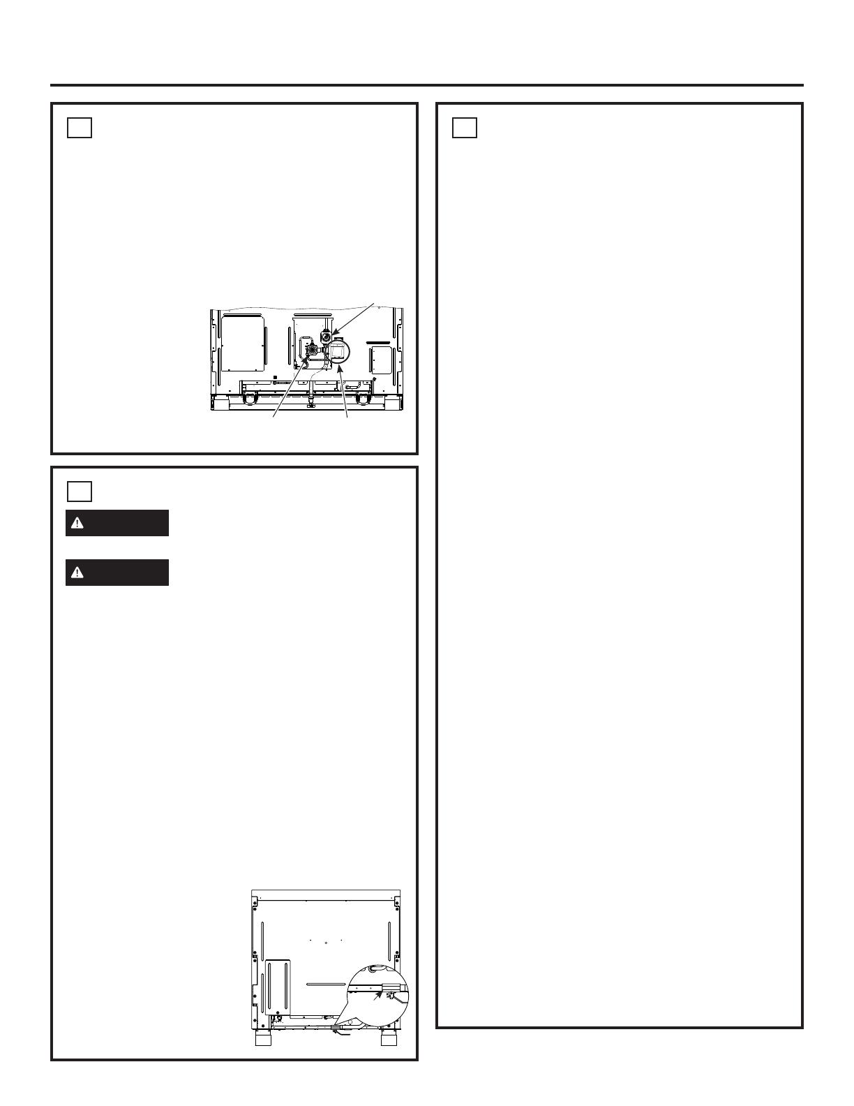
CONVERTING TO PROPANE (LP)
GAS OR CONVERTING BACK
TO NATURAL GAS FROM
PROPANE (LP)
This range leaves the factory set for use with natural
JDV,I\RXZDQWWRFRQYHUWWRSURSDQH/3JDVWKH
conversion must be performed by a qualified propane
(LP) gas installer.
The conversion orifices
and instructions can
be found on back of
the range.
Keep these
instructions and all
orifices in case you
want to convert back
to natural gas.
5
GAS SUPPLY
WARNING
)LUH+D]DUG'RQRWXVHDIODPHWR
check for gas leaks.
WARNING
([SORVLRQ+D]DUG'RQRWH[FHHG
25 ft-lbs of torque when making gas line connections.
Overtightening may damage the pressure regulator
UHVXOWLQJLQILUHRUH[SORVLRQKD]DUG
Gas Pressure Regulator
You must use the gas pressure regulator supplied
with this range. For proper operations the inlet
SUHVVXUHWRWKHUHJXODWRUVKRXOGEHDVIROORZV
Natural Gas:
0LQLPXPSUHVVXUH´RI:DWHU&ROXPQ
0D[LPXPSUHVVXUH´RI:DWHU&ROXPQ
Propane (LP) Gas:
0LQLPXPSUHVVXUH´RI:DWHU&ROXPQ
0D[LPXPSUHVVXUH´RI:DWHU&ROXPQ
If you are not sure about the inlet pressure contact
local gas supplier.
NOTE: A gas shutoff valve is shipped with this range
and should be installed at the rear of the range near
the floor with the handle facing downward. This shut-
off valve is to be used in
the event that service is
required. To access the
VKXWRIIYDOYHUHPRYHWKH
toe-kick panel and reach
under the range. An optional
´HOERZLVSURYLGHGIRU
connection to the range gas
inlet.
5
GAS SUPPLY (cont.)
Shut off the main gas supply valve before
disconnecting the old range and leave it off until
the new hook-up has been completed. Don’t
forget to relight the pilot on other gas appliances
when you turn the gas back on.
%HFDXVHKDUGSLSLQJUHVWULFWVPRYHPHQWRIWKHUDQJH
WKHXVHRID&6$,QWHUQDWLRQDOFHUWLILHGIOH[LEOHPHWDO
appliance connector is recommended unless local
codes require a hard-piped connection.
,IWKHKDUGSLSLQJPHWKRGLVXVHG\RXPXVWFDUHIXOO\
DOLJQWKHSLSHWKHUDQJHFDQQRWEHPRYHGDIWHUWKH
connection is made.
7RSUHYHQWJDVOHDNVSXWSLSHWKUHDGVHDODQWRQRU
ZUDSSLSHWKUHDGWDSHZLWK7HIORQDURXQGDOOPDOH
H[WHUQDOSLSHWKUHDGV
A. Install a manual shut-off valve in the gas line in an
easily accessed location outside of the range. Make
sure everyone operating the range knows where
and how to shut off the gas supply to the range.
% ,QVWDOOPDOH´IODUHXQLRQDGDSWHUWRWKH´
NPT internal thread at inlet of the shut-off valve on
the range. Use a backup wrench on the shut-off
valve to avoid damage.
& ,QVWDOOPDOH´RU´IODUHXQLRQDGDSWHUWRWKH
137LQWHUQDOWKUHDGRIWKHKRXVHVKXWRIIYDOYH
taking care to back-up the shut-off valve to keep it
from turning.
' &RQQHFWIOH[LEOHPHWDODSSOLDQFHFRQQHFWRUWRWKH
adapter on the range. Position range to permit
connection at the house shut-off valve.
( :KHQDOOFRQQHFWLRQVKDYHEHHQPDGHPDNHVXUH
all range controls are in the off position and turn
on the main gas supply valve. Use a liquid leak
detector at all gas connections to check for leaks
in the system.
:KHQXVLQJSUHVVXUHVJUHDWHUWKDQSVLJWR
SUHVVXUHWHVWWKHJDVVXSSO\V\VWHPRIWKHUHVLGHQFH
disconnect the range and individual shut-off valve
from the gas supply piping. When using pressures
RISVLJRUOHVVWRSUHVVXUHWHVWWKHJDVVXSSO\
V\VWHPVLPSO\LVRODWHWKHUDQJHIURPWKHJDVVXSSO\
system by closing the individual shut-off valve.
:KHQFKHFNLQJIRUSURSHURSHUDWLRQRIWKHUHJXODWRU
the inlet pressure must be at least 1” greater than the
operating (manifold) pressure as given on rating label
of product.
7HIORQ5HJLVWHUHGWUDGHPDUNRI'X3RQW
Gas Inlet
Oven
Regulator
Cooktop Regulator
Propane
Conversion Kit
12 31-2000815 Rev. 0
Installation
6
ELECTRICAL CONNECTIONS
WARNING
This appliance must be properly
grounded.
WARNING
$OOQHZFRQVWUXFWLRQVPRELOH
KRPHVUHFUHDWLRQDOYHKLFOHVDQGLQVWDOODWLRQVZKHUH
ORFDOFRGHVGRQRWDOORZJURXQGLQJWKURXJKQHXWUDO
require a 4-conductor UL-listed range cord.
WARNING
7RSUHYHQWILUHRUVKRFNGRQRWXVH
DQH[WHQVLRQFRUGZLWKWKLVDSSOLDQFH
WARNING
7RSUHYHQWVKRFNUHPRYHKRXVH
fuse or open circuit breaker before beginning
installation.
We recommend you have the electrical wiring and
hookup of your range connected by a qualified
HOHFWULFLDQ$IWHULQVWDOODWLRQKDYHWKHHOHFWULFLDQVKRZ
you how to disconnect power from the range.
<RXPXVWXVHDVLQJOHSKDVH9$&RU
9$&KHUW]HOHFWULFDOV\VWHP,I\RX
FRQQHFWWRDOXPLQXPZLULQJSURSHUO\LQVWDOOHG
connectors approved for use with aluminum wiring
must be used.
(IIHFWLYH-DQXDU\WKH1DWLRQDO(OHFWULFDO
&RGHUHTXLUHVWKDWQHZFRQVWUXFWLRQQRWH[LVWLQJ
utilize a 4-conductor connection to an electric range.
:KHQLQVWDOOLQJDQHOHFWULFUDQJHLQQHZFRQVWUXFWLRQ
PRELOHKRPHUHFUHDWLRQDOYHKLFOHRUDQDUHDZKHUH
local codes prohibit grounding through the neutral
FRQGXFWRUUHIHUWRWKHVHFWLRQRQIRXUFRQGXFWRU
branch circuit connections.
Check with your local utilities for electrical codes which
apply in your area. Failure to wire your oven according
to governing codes could result in a hazardous
FRQGLWLRQ,IWKHUHDUHQRORFDOFRGHV\RXURYHQPXVW
be wired and fused to meet the National Electrical
&RGH1)3$1R±ODWHVWHGLWLRQDYDLODEOHIURPWKH
National Fire Protection Association.
This appliance must be supplied with the proper
YROWDJHDQGIUHTXHQF\DQGFRQQHFWHGWRDQLQGLYLGXDO
SURSHUO\JURXQGHGDPSIRU´UDQJHVDPS
for 36” and 30” ranges) branch circuit protected by a
circuit breaker or time-delay fuse.
Use only a 3-conductor or a 4-conductor UL-listed
range cord. These cords may be provided with ring
terminals on wire and a strain relief device.
6
ELECTRICAL CONNECTIONS (Cont.)
$UDQJHFRUGUDWHGDWDPSVZLWKPLQLPXP
volt range is required. A 50 amp range cord is not
UHFRPPHQGHGEXWLIXVHGLWVKRXOGEHPDUNHGIRU
use with nominal 1
3
»8” diameter connection openings.
Care should be taken to center the cable and strain
relief within the knockout hole to keep the edge from
damaging the cable.
NOTE:8VHRIDXWRPDWLFZLUHOHVVRUZLUHGH[WHUQDO
VZLWFKHVWKDWVKXWRIISRZHUWRWKHDSSOLDQFHVDUHQRW
recommended for this product.
7
4-WIRE POWER CORD
INSTALLATION
NOTE: A 4-wire cord is connected to the range at the
IDFWRU\8VHWKHIROORZLQJVWHSVWRFKDQJHDQH[LVWLQJ
installation from a 3-wire cord back to a 4-wire cord.
WARNING
The neutral wire of the supply circuit
must be connected to the neutral terminal located
in the lower center of the terminal block. The power
leads must be connected to the lower left and the
lower right terminals of the terminal block. The 4th
grounding lead must be connected to the frame of the
range with the ground plate and the ground screw.
ŶRemove the 3 lower terminal screws from the
terminal block. Remove the ground screw and
ground plate and retain them.
ŶRemove the ground strap.
DO NOT DISCARD THE GROUND STRAP OR
ANY SCREWS.
ŶInsert the one ground screw into the power cord
JURXQGZLUHWHUPLQDOULQJWKURXJKWKHJURXQGSODWH
and into the frame of the range.
The access
plate is on
the back of
the range.
31-2000815 Rev. 0 13
9
ROLL RANGE INTO POSITION
WARNING
The Anti-Tip Bracket must be
properly installed to prevent tipping of the range.
Failure to do so can cause serious damage or injury.
Ŷ&KHFNWREHVXUHWKHDSSOLDQFHUXQQHUVDUH
beneath the wheels.
Ŷ7KHUDQJHLVVKLSSHGZLWKWKHZKHHOVLQWKHGRZQ
SRVLWLRQ&DUHIXOO\UROOWKHUDQJHLQWRSRVLWLRQEHLQJ
careful not to entangle or pinch the power cord and
IOH[LEOHJDVWXELQJ
Ŷ5HPRYHWKHUXQQHUVEHQHDWKWKHUDQJH
Be sure Anti-Tip
Bracket is engaged
with the brace on
the range.
Installation
7
4-WIRE POWER CORD
INSTALLATION (Cont.)
ŶInsert the 3 terminal screws (removed earlier)
through each power cord terminal ring and into the
lower terminals of the terminal block. Be certain that
WKHFHQWHUZLUHZKLWHQHXWUDOLVFRQQHFWHGWRWKH
center lower position of the terminal block. Tighten
screws securely into the terminal block.
8
3-WIRE POWER CORD
INSTALLATION
NOTE: A 4-wire cord is connected to the range at the
factory. Use the following steps to change the range
to a 3-wire cord.
WARNING
The neutral or ground wire of the
power cord must be connected to the neutral terminal
located in the center of the terminal block. The power
leads must be connected to the lower left and the
lower right terminals of the terminal block.
Ŷ5HPRYHWKHJURXQGVWUDSORFDWHGDWWKHULJKWVLGH
of the terminal block) and connect between the
center lower portion of the terminal block to the
frame of the range.
8
3-WIRE POWER CORD
INSTALLATION (Cont.)
Ŷ5HPRYHWKHORZHUWHUPLQDOVFUHZVIURPWKH
terminal block. Insert the 3 terminal screws through
each power cord terminal ring and into the lower
terminals of the terminal block. Be certain that
WKHFHQWHUZLUHZKLWHQHXWUDOLVFRQQHFWHGWRWKH
center lower position of the terminal block. Tighten
screws securely into the terminal block.
DO NOT REMOVE THE GROUND STRAP
CONNECTION.
Before
After
Terminal
Block
Terminal
Block
Neutral
Terminal
Neutral Terminal
Ground Strap
Ground Plate
(grounding to
range)
Ground
Screw
Ground Strap
or
Ground
Strap
Terminal Block
(appearance may vary)
Neutral
Terminal
Power Cord
Ground
Plate
14 31-2000815 Rev. 0
Installation
10
LEVEL THE RANGE
WARNING
The range must be level and be
supported by the legs—not the wheels. The range could
move if the wheels make contact with the floor. Be sure
all legs make contact with the floor in any installation.
Ŷ$OOOHJVPXVWEHOHYHOHGDIWHUWKHSURGXFWLVLQVWDOOHG
Ŷ&KHFNWREHVXUHWKHDGMRLQLQJFDELQHWVFRXQWHUWRSV
DUHOHYHOIURQWWREDFNDQGOHIWWRULJKWDFURVVWKH
opening of the range.
Ŷ
Measure the distance from the floor to the top of the
countertop in the left and right rear corners.
Ŷ
Adjust the height of the range to countertop height
or higher.
IMPORTANT: This range should always be installed
at countertop height or higher. DO NOT INSTALL THE
RANGE LOWER THAN ADJACENT COUNTERTOP
+(,*+77KHUDQJHPXVWEHVXSSRUWHGE\DOOOHJV
regardless of countertop height.
FRONT LEG ADJUSTMENT
Ŷ$OHYHOLQJOHJZUHQFKLVVXSSOLHG5HDFKXQGHUWKH
front of the range near the right leg. Locate and
UHPRYHDWKXPEVFUHZWKHQVOLGHZUHQFKRXWRI
the slot.
Ŷ6OLGHIURQWF\OLQGHUVXSWRDFFHVVIURQWOHYHOLQJOHJV
Be careful not to damage cylinder.
Ŷ8VHWKHVXSSOLHGZUHQFKWRDGMXVWWKHIURQWOHYHOLQJ
OHJV7XUQFORFNZLVHWRH[WHQGWKHOHJVWROLIWDQG
stabilize the range. Turn counterclockwise to retract
the legs and allow the range to rest on its rollers.
Ŷ%HVXUHWRUHWXUQWKHZUHQFKWRLWVVWRUDJHVORWIRU
future use.
10
LEVEL THE RANGE (cont.)
REAR LEG ADJUSTMENT
WARNING
To reduce the risk of fire or electric
VKRFNDOZD\VUHSODFHWKHVSLOOSOXJVLQWKHOHYHOLQJ
rod holes.
Ŷ
Remove two screws from rear vent trim. Slide vent
WULPIRUZDUGWKHQOLIWXSWRUHPRYH
Ŷ
Remove the 2 spill plugs to locate the rear leg
H[WHQVLRQOHYHOLQJURGV8VHD´GULYHURUVRFNHW
wrench to adjust the left or right rear legs.
Ŷ
)LQGWKHWZRUHDUOHJH[WHQVLRQURGV8VHD´GULYHU
or wrench to adjust the left or right rear legs.
Ŷ
Replace the 2 spill plugs and then replace the rear
vent trim using the original screws.
Slide leg
cylinder up.
Thumb Screw
11
REPLACE OVEN DOOR(S)
Skip this step if oven doors are in place.
IMPORTANT: Do not lift the door by the handle.
To replace the oven doors:
Ŷ
Firmly grasp the door at the top sides. This is critical.
Ŷ$SSURDFKWKHUDQJHZLWKWKHGRRUDQJOHGLQD
vertical position.
Ŷ*XLGHWKHKLQJHVLQWRWKHVORWV
Ŷ3XVKWKHGRRULQILUPO\ZKLOHRSHQLQJ
Ŷ2QFHLQSRVLWLRQRSHQWKHGRRUFRPSOHWHO\3XVK
the hinge locks back in toward the front frame.
CAUTION
Take care when replacing the oven
doors. If the hinge latch
LVQRWVHFXUHO\ORFNHG
the hinge may snap back
and separate. If the hinge
VHSDUDWHV\RXPXVWDSSO\
pressure (possibly with
your foot) to press it back
together and then engage
the hinge latch.
Spill Plugs
Rear Leg
([WHQVLRQ
Rods
31-2000815 Rev. 0 15
Installation
12
CHECK BURNERS
WARNING
)LUHRU([SORVLRQ+D]DUG'RQRW
operate the burner without all burner parts in place.
A. Burners - Place surface burners into corresponding
positions on cooktop.
B. Caps - Place caps on proper size burner.
C. Grates - The left and right grates are
interchangeable. Place the grates on the cooktop.
FINALIZE INSTALLATION
Place the burner grates over the burners. The grates
should be seated and should not rock.
The griddle is secured with screws. It is designed to
be stationary and should not be removed.
The griddle has two leveling screws beneath the rear flue
cover that can be used to adjust to the desired slope.
The two inner screws are clamping screws for
securing the griddle in place. Loosen these two screws
before leveling. Do not remove these two screws.
The two outer screws are leveling screws. Do not
remove these two screws. They can be turned to level
the griddle or to provide a forward slope to help grease
and oils drain away from the food being cooked.
$IWHUOHYHOLQJWKHJULGGOHKDQGWLJKWHQWKHFODPSLQJ
VFUHZVGRQRWRYHUWLJKWHQ
WHEN ALL HOOKUPS ARE
COMPLETED
Make sure all controls are left in the off position. Make
sure the flow of combustion and ventilation air to the
range is unobstructed.
Check that all packing materials and tape have been
removed. This will include tape on metal panel under
FRQWURONQREVLIDSSOLFDEOHDGKHVLYHWDSHZLUH
WLHVFDUGERDUGDQGSURWHFWLYHSODVWLF)DLOXUHWR
remove these materials could result in damage to the
appliance once the appliance has been turned on and
surfaces have heated.
13
CHECK SURFACE BURNERS
Push and turn a knob to the LITE position. A clicking
sound indicates proper operation of the ignition
V\VWHP:KHQOLJKWLQJDQ\EXUQHUVSDUNVZLOODSSHDU
at all burners but gas flows from only the one selected.
2QFHDLULVSXUJHGIURPWKHVXSSO\OLQHEXUQHUVKRXOG
OLJKWZLWKLQVHFRQGV$IWHUEXUQHUOLJKWVURWDWHWKH
knob out of the LITE position. Try each burner in
succession until all burners have been checked.
Quality of Flames
Determine the quality of flames visually. Normal
burner flames should look like (A) or (B).
/RQJEULJKW\HOORZIODPHVDUHQRWQRUPDO1RUPDO
flames may show signs of an orange tint when well
heated or signs of flickering orange due to particles in
the gas or air.
(A) Soft blue flames—
Normal for natural gas
(B) Yellow tips on
outer cones—
Normal for propane (LP) gas
Burner Cap Not Properly Seated
Burner Cap Properly Seated
Griddle Flue Cover
Clamping Screws
Leveling Screws
16 31-2000815 Rev. 0
Accessory Installation
TOEKICK (included)
Ŷ,QVWDOOWKHWRHNLFNDIWHUWKHUDQJHKDVEHHQOHYHOHG
Ŷ0HDVXUHWKHGLVWDQFHEHWZHHQWKHIORRUDQGWKH
bottom of range.
Ŷ/RRVHQWKHWZRVFUHZVRQHDFKHQG$GMXVWWKH
toekick height by sliding the upper and lower pieces
DSDUWWR´OHVVWKDQWKHPHDVXUHGKHLJKW
Ŷ6HFXUHWKHWRSDQGERWWRPVHFWLRQVE\WLJKWHQLQJWKH
screws on each end.
Ŷ3XVKWRHNLFNDJDLQVWUDQJHOHJXQWLOFOLSVQDSVWROHJV
NOTE: Be sure the toekick snaps securely to the leg.
Bottom
of Toekick
Screw
Top of
Toekick
Push
Push
31-2000815 Rev. 0 17
OPTIONAL ACCESSORIES—12 HIGH BACKSPLASH
UX12BS36PSS, UX12BS48PSS Accessory Installation
This kit provides for the installation of a 12” high
backsplash for 36” Professional Ranges and Rangetops.
TOOLS AND MATERIALS REQUIRED
Ŷ*ORYHVWRSURWHFWDJDLQVWVKDUSHGJHV
Ŷ7DQG3KLOOLSV
screwdrivers
Ŷ'ULOOZLWK´DQG
´ELWV
Ŷ6DIHW\JODVVHV
Ŷ/HYHO
Ŷ3HQFLO
This Kit Includes
Ŷ:DOOVXSSRUWSDQHO
Ŷ&RYHUSDQHO
Ŷ+DUGZDUHSDFNDJHZLWK
±6WDLQOHVV6WHHO7RU[
#8 self-tapping screws
±3KLOOLSVSDQKHDGZRRG
#10 screws
INSTALL 12” BACKSPLASH
WARNING
This backsplash must be securely
fastened to the wall. Failure to do so could result in
damage or personal injury.
Ŷ,QVWDOODQGOHYHOWKHUDQJHRUUDQJHWRSDQGWKH
range hood according to the installation instructions.
Ŷ5HPRYHWKHEDFNVSODVKSDFNDJLQJDQGSURWHFWLYH
film.
Ŷ8VHDOHYHOWRSHQFLODKRUL]RQWDOOLQHRQWKHZDOO´
DERYHWKHUDQJHRUUDQJHWRS7KH´JDSDOORZVWKH
cover panel to overlap the wall support panel.
Ŷ/RFDWHZDOOVWXGVRQHDFKVLGH:KHUHVWXGVDUHQRW
DYDLODEOHSODQWRXVHZDOODQFKRUVQRWSURYLGHG
Ŷ$OLJQWKHZDOOVXSSRUWSDQHORQWKHPDUNHG
horizontal line and centered left to right.
Ŷ7KHZDOOVXSSRUWSDQHOPXVWEHVHFXUHGWRWKHZDOO
at all 4 corners. Use wood screws (provided) or wall
anchors (not provided) to secure the support panel
to the wall.
Ŷ3ODFHWKHFRYHUSDQHORYHUWKHZDOOVXSSRUWSDQHO
DQGVHFXUHZLWK7RU[VFUHZVSURYLGHG,QVWDOO
screws on each side.
Wall Support Panel
Cover Panel
Hardware
Package
Install 4 Wood Screws
Install T-15
Screws
Wall
Support
Panel
Wall Support
Panel
Cover Panel
Center
Arrow
´
18 31-2000815 Rev. 0
ACCESSORIES—30” TO 36” ADJUSTABLE BACKSPLASH (not included)
UXADBS36PSS, UXADBS48PSS Accessory Installation
Ŷ7KLVEDFNVSODVKDGMXVWVWRILWWKHVSDFHEHWZHHQ
WKHWRSRIWKHUDQJHDQGWKHERWWRPRIWKHKRRG
IURP´0LQWR´0D[KHLJKW
Ŷ0D[LPXPVKHOIORDGEHDULQJZHLJKWLVOEV
TOOLS AND MATERIALS REQUIRED
Ŷ*ORYHVWRSURWHFWDJDLQVWVKDUSHGJHV
Ŷ7DQG3KLOOLSVVFUHZGULYHUV
Ŷ'ULOOZLWK´DQG´ELWV
Ŷ6DIHW\JODVVHV
Ŷ/HYHO
Ŷ3HQFLO
This Kit Includes
Ŷ7RSZDOOVXSSRUW
Ŷ%RWWRPZDOOVXSSRUW
Ŷ7RSFRYHUZLWKVKHOI
Ŷ%RWWRPFRYHU
Ŷ+DUGZDUHSDFNDJHZLWK
±6WDLQOHVV6WHHO7RU[
self-tapping screws
±3KLOOLSVSDQKHDGZRRG
#10 screws
±6WDLQOHVV6WHHOWUXVVKHDG
#10 screws (for alternate
installation method)
INSTALL THE WALL SUPPORT PANELS
WARNING
The wall support panels must be
securely fastened to the wall. Failure to do so could
result in damage or personal injury.
IMPORTANT: This backsplash is designed to cover
the wall between the bottom of the hood and the top of
the range. The vent hood should be installed over the
rangetop or range before installing this backsplash.
Ŷ,QVWDOODQGOHYHOWKH5DQJH5DQJHWRSDFFRUGLQJWR
the product installation instructions.
Ŷ5HPRYHEDFNVSODVKSDFNDJLQJDQGSURWHFWLYHILOP
Ŷ/RFDWHZDOOVWXGVRQHDFKVLGH:KHUHVWXGVDUHQRW
DYDLODEOHSODQWRXVHZDOODQFKRUVQRWSURYLGHG
Ŷ8VHDOHYHOWRSHQFLOKRUL]RQWDOOLQHVRQWKHZDOO
RQH´EHORZWKHYHQWKRRGDQGWKHRWKHU´
DERYHWKH5DQJH5DQJHWRS7KLV´VSDFHDOORZV
the cover panels to overlap the wall supports.
Ŷ6HFXUHWKHWRSZDOOVXSSRUWSDQHOWRWKHZDOOZLWK
ZRRGVFUHZVWKURXJKWKHRXWHUPRVWVWXGV
Ŷ8VHZRRGVFUHZVWRVHFXUHWKHERWWRPZDOOVXSSRUW
panel. The center slot should be positioned at the top.
The gap between the top and bottom support panels
will be covered by the top cover with shelf.
Hardware
Package
Top Cover
with Shelf
Bottom Cover
Bottom Wall Support
Top Wall
Support
´
Secure the
top panel to
the wall with 4
wood screws
´
Secure the
bottom panel to
the wall with 4
wood screws
Wood
Screws
Center
Arrow
Wood
Screws
31-2000815 Rev. 0 19
INSTALL COVER PANELS
See alternate method if side access is blocked.
Ŷ+ROGWKHERWWRPFRYHURYHUWKHERWWRPVXSSRUW
while driving one screw (provided) into each side.
Ŷ3ODFHWKHWRSFRYHUZLWKVKHOIRYHUWKHWRSZDOO
VXSSRUW,I\RXKDYHDFFHVVWRWKHVLGHVVHFXUHWKH
panel with two screws on each side.
Ŷ6HFXUHWKHWRSFRYHUZLWKVKHOIWRWKHWRSVXSSRUW
ZLWKVFUHZVWKURXJKWKHIURQWRIWKHSDQHODWWKHWRS
corners. Use one screw on each side.
INSTALL COVER PANELS (cont.)
ALTERNATE METHOD: When side access is blocked
Ŷ,QVWDOOERWWRPFRYHURYHUWKHERWWRPVXSSRUWZKLOH
driving one screw into each side.
Ŷ+ROGWRSFRYHULQSODFHZKLOHPDUNLQJVFUHZORFDWLRQV
just below shelf support and onto bottom cover.
Ŷ5HPRYHWKHVKHOIDQGGULOOD´GLDPHWHUKROHLQ
the pencil-marked locations.
Ŷ0RXQWWKHWRSFRYHURYHUWKHWRSVXSSRUWDQG
secure the front cover with screws through the
drilled holes on each side.
Ŷ,QVWDOOVFUHZVWKURXJKHDFKWRSFRUQHU
Mark Screw
Locations for
Alternate Method
ACCESSORIES—30” TO 36” ADJUSTABLE BACKSPLASH (not included) (Cont.)
UXADBS36PSS, UXADBS48PSS Accessory Installation
Install
Screw
Cover Panel
Install
Screw
Install Corner Screws
Install Screw
on Each Side
Shelf
Install Screw in Top Corner on Each Side
20 31-2000815 Rev. 0
NOTE: :KLOHSHUIRUPLQJLQVWDOODWLRQVGHVFULEHGLQWKLVERRN
safety glasses or goggles should be worn.
NOTE: Product improvement is a continuing endeavor at
*($SSOLDQFHV7KHUHIRUHPDWHULDOVDSSHDUDQFHDQG
specifications are subject to change without notice.
3ULQWHGLQ0H[LFR
  • Page 1 1
  • Page 2 2
  • Page 3 3
  • Page 4 4
  • Page 5 5
  • Page 6 6
  • Page 7 7
  • Page 8 8
  • Page 9 9
  • Page 10 10
  • Page 11 11
  • Page 12 12
  • Page 13 13
  • Page 14 14
  • Page 15 15
  • Page 16 16
  • Page 17 17
  • Page 18 18
  • Page 19 19
  • Page 20 20
  • Page 21 21
  • Page 22 22
  • Page 23 23
  • Page 24 24
  • Page 25 25
  • Page 26 26
  • Page 27 27
  • Page 28 28
  • Page 29 29
  • Page 30 30
  • Page 31 31
  • Page 32 32
  • Page 33 33
  • Page 34 34
  • Page 35 35
  • Page 36 36
  • Page 37 37
  • Page 38 38
  • Page 39 39
  • Page 40 40
  • Page 41 41
  • Page 42 42
  • Page 43 43
  • Page 44 44
  • Page 45 45
  • Page 46 46
  • Page 47 47
  • Page 48 48
  • Page 49 49
  • Page 50 50
  • Page 51 51
  • Page 52 52
  • Page 53 53
  • Page 54 54
  • Page 55 55
  • Page 56 56
  • Page 57 57
  • Page 58 58
  • Page 59 59
  • Page 60 60

GE 1046151 Le manuel du propriétaire

Catégorie
Cuisinières
Taper
Le manuel du propriétaire

dans d''autres langues