
PUSH
TRONIC
ENGLISH
DEUTSCH
FRANÇAIS
390 2221 | 390 2231 | 390 2321 | 390 2331 | 390 4221 | 390 4231 | 390 4321 | 390 4331
390 2221 S | 390 4221 S

PUSH
TRONIC
4 Buttons im Lieferumfang enthalten / 4 buttons included / 4 boutons inclus

4 5
1
4
2
5
7
8
3
6
9
10
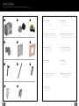
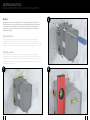
LIEFERUMFANG
1. Unterputzkörper
Concealed box
Corps d‘encastrement
3. Spannhülsen 11,6 mm (18,5 mm)
Clamping sleeves 11.6 mm (18.5 mm)
Douille de serrage 11,6 mm (18,5 mm)
5. Schallschutzmatte
Soundproofing mat
Tapis d‘insonorisation
7. Steckschlüssel
Socket wrench
Clé
9. Schrauben 63,5 mm (50 mm)
Screws 63.5 mm (50 mm)
Vis 63,5 mm (50 mm)
11. Dübel 8 x 40
Screw anchors 8 x 40
Chevilles 8 x 40
ITEMS SUPPLIED | CONTENU DE LA LIVRAISON
11
2. Ersatzbutton
Additional Button
Bouton de rechange
4. Übergangsstücke 16,9 mm (23,8 mm)
Couplings 16.9 mm (23.8 mm)
Pièces de raccordement 16,9 mm (23,8 mm)
6. Kerdi Dichtmanschette
Kerdi waterproofing membrane
Tapis d
‘
étanchéité Kerdi
8. Montagelehre
Fixing template
Gabarit de montage
10. Befestigungsschrauben M4 x 30
Fixing screws M4 x 30
Vis de fixation M4 x 30

6 7
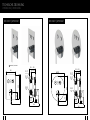
390 2231
50
3,6
85 ~ 105
60 ~ 80
144
G1/2"
G3/4"
G1/2"
2x
2x
145
54,5
200
235
390 2331
50
3,6
60 ~ 80
85 ~105
144
G1/2"
G3/4"
G1/2"
2x
2x
200
235
54,5
390 2231
50
3,6
85 ~ 105
60 ~ 80
144
G1/2"
G3/4"
G1/2"
2x
2x
145
54,5
200
235
390 2221 | 390 2231
390 2331
50
3,6
60 ~ 80
85 ~105
144
G1/2"
G3/4"
G1/2"
2x
2x
200
235
54,5
390 2321 | 390 2331
TECHNISCHE ZEICHNUNG
DIMENSIONS | DIMENSIONS
Ma Black | 390 2221 S

8 9
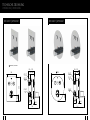
390 4331
50
3,6
60 ~80
85 ~105
161
G1/2"
G3/4"
G1/2"
2x
2x
200
54,5
390 4221 | 390 4231 390 4321 | 390 4331
390 4231
50
3,6
85 ~ 105
60 ~ 80
161
G1/2"
G3/4"
G1/2"
2x
2x
145
54,5
200
390 4231
50
3,6
85 ~ 105
60 ~ 80
161
G1/2"
G3/4"
G1/2"
2x
2x
145
54,5
200
390 4331
50
3,6
60 ~80
85 ~105
161
G1/2"
G3/4"
G1/2"
2x
2x
200
54,5
TECHNISCHE ZEICHNUNG
DIMENSIONS | DIMENSIONS
Ma Black | 390 4221 S

10 11
MONTAGEANLEITUNG
INSTALLATION INSTRUCTIONS | GUIDE D‘INSTALLATION
1
2
3
Allgemein
Die Montageanleitung beinhaltet Vorgaben für die vorschriftsgemäße Installation der Pushtronic.
Die Produktgarantie erlischt, wenn das Produkt nicht gemäß der Montageanleitung installiert wird.
Die Montage ist nur durch qualifizierte Sanitärinstallations-Fachbetriebe unter Beachtung dieser
Montageanleitung und den länderspezifisch geltenden Normen, Regelungen und Sicherheits-
bestimmungen zulässig.
Important information
This manual contains instructions for proper installation and commissioning of the Pushtronic.
Warranty will be void if this product is not installed and commissioned as stated in this manual.
Installation and commissioning must be done as stated in this manual and by a fully qualified sanitary
installation business and must comply with applicable standards and safety regulations in your country.
Informations générales
L’instruction de montage fournit des indications pour une installation conforme du Pushtronic.
La garantie du produit sera caduque si le produit n‘a pas été installé conformément à l’instruction de
montage. Seule une entreprise spécialisée d‘installations sanitaires est habilitée à réaliser le montage
conformément à la présente instruction de montage et aux normes, réglementations et consignes de
sécurité en vigueur dans le pays.

12 13
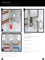
4.2
Dichtheitsprüfung bei 16 Bar
Die Schalterstellung wird durch leichtes Wackeln an den Spannhülsen festgestellt:
Spannhülse lose = Ventil geschlossen
Spannhülse fest = Ventil offen
Leakproofness test at 16 bar
Identify On/Off position by slightly wiggling the clamping sleeves:
Clamping sleeve loose = valve closed
Clamping sleeve tight = valve open
Test d‘étanchéité à 16 bar
Vérifier la position de l‘interrupteur (ouvert/fermé) en bougean légèrement les douilles de serrage:
Douille de serrage desserrée = vanne fermée
Douille de serrage serrée = vanne ouverte
Anschließend Leitungen spülen. Variable Anordnung der Anschlüsse und Buttons.
Rinse piping after installation. Outlets and push buttons may be arranged freely.
Rincer ensuite la tuyauterie. Disposition flexible des boutons poussoirs.
Les sorties et les boutons poussoirs peuvent êtres disposés librement.
5
MONTAGEANLEITUNG
INSTALLATION INSTRUCTIONS | GUIDE D‘INSTALLATION
4.1
4

14 15
6
7
8
MONTAGEANLEITUNG
INSTALLATION INSTRUCTIONS | GUIDE D‘INSTALLATION
Bitte Montagemaß beachten!
Grün = Nutzbarer Einbaubereich bis Vorderkante Fertigwand
Rot = Außerhalb des vorgeschriebenen Einbaumaßes, bitte vermeiden/korrigieren
Please note clearance requirements:
Green = usable space up to face of finished wall /tiling
Red = outside tolerance – make sure to avoid or correct
S‘il vous plaît prêter attention à la dimension de montage !
Vert = surface d‘installation utilisable jusqu‘au bord avant le mur fini (avec carrelage, etc.)
Rouge = en dehors de la dimension d‘installation prescrite, veuillez éviter/corriger

16 17
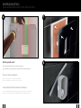
Für die korrekte Montage der Schubrosette die Schrauben und Spannhülsen bis zur jeweiligen Kante der
Montage hilfe drehen
(Spannhülse fest).
Wenn nötig die anderen werksseitig gelieferten Spann hülsen/
Übergangsstücke und Schrauben verwenden. (Abb. 9.1 und 9.2)
Before applying cover plate, turn bolds and clamping sleeves to be even with respective edge of fixing
template (clamping sleeves tight). If necessary use clamping sleeves, couplings and and bolts of different
size additionally supplied. (Fig. 9.1 and 9.2)
Pour une installation correcte de la plaque de recouvrement, tournez les vis et douilles de serrage sur le
bord du gabarit de montage (douilles de serrage fixes). Si nécessaire, utilisez les autres douilles de serrage,
pièces de raccordement et vis (différentes tailles fournies) (Fig. 9.1 et 9.2).
9
9.29.1
Einhebelmischer
Single lever mixer
Mitigeur mono commande
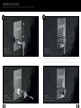
Schutzkappe abziehen und Rosette aufschieben, dann Buttons auf die Spannhülsen drücken.
Remove protective sheath and apply cover plate. Press control buttons onto respective clamping sleeve.
Poussez la plaque de recouvrement sur le corps et poussez les boutons en appuyant sur les douilles de serrage.
Thermostat
Thermostatic mixer
Mélangeur thermostatique
10
MONTAGEANLEITUNG
INSTALLATION INSTRUCTIONS | GUIDE D‘INSTALLATION

18 19
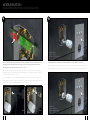
Im eingeschalteten Zustand müssen die Bedienknöpfe 7–9 mm aus der Abdeckung hervorstehen.
In On position, control buttons must protrude by 7–9 mm from cover plate.
En position ouvert, les boutons de commande doivent dépasser de 7 à 9 mm du plaque de recouvrement.
12
11
Einhebelmischer
Single lever mixer
Mitigeur mono commande
Thermostat
Thermostatic mixer
Mélangeur thermostatique
Einhebelmischer
Single lever mixer
Mitigeur mono commande
Thermostat
Thermostatic mixer
Mélangeur thermostatique
MONTAGEANLEITUNG
INSTALLATION INSTRUCTIONS | GUIDE D‘INSTALLATION

STEINBERG GmbH
Schiess-Str. 30
D-40549 Düsseldorf
Tel. +49 (0)211 520 249-0
Fax: +49 (0) 211 520 249 -20
info@steinberg-armaturen.de
www.steinberg-armaturen.de
sensual
R
AIN
Der Hersteller behält sich das Recht vor, ohne vorherige Ankündigung technische Änderungen vorzunehmen.
The manufacturer reserves the right to make technical modications without prior notice.
Le fabricant se réserve le droit d‘apporter des modications techniques sans préavis.
-
 1
1
-
 2
2
-
 3
3
-
 4
4
-
 5
5
-
 6
6
-
 7
7
-
 8
8
-
 9
9
-
 10
10
-
 11
11


