Bosch GSB18V-535CB15 Manuel utilisateur
- Catégorie
- Marteaux rotatifs
- Taper
- Manuel utilisateur

IMPORTANT: IMPORTANT : IMPORTANTE:
Read Before Using Lire avant usage Leer antes de usar
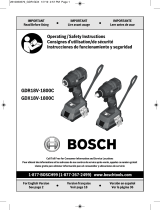
Operating/Safety Instructions
Consignes de fonctionnement/sécurité
Instrucciones de funcionamiento y seguridad
1-877-BOSCH99 (1-877-267-2499) www.boschtools.com
Call Toll Free for
Consumer Information
& Service Locations
Pour obtenir des informations
et les adresses de nos centres
de service après-vente,
appelez ce numéro gratuit
Llame gratis para
obtener información
para el consumidor y
ubicaciones de servicio
GSB18V-535C
GSR18V-535C
For English Version
See page 2
Version française
Voir page 19
Versión en español
Ver la página 36
2610045250.qxp_GSB18V-535C 7/7/17 9:41 AM Page 1

2 SAVE THESE INSTRUCTIONS
Work area safety
Keep work area clean and well lit. Cluttered or
dark areas invite accidents.
Do not operate power tools in explosive
atmospheres, such as in the presence of
flammable liquids, gases or dust. Power tools
create sparks which may ignite the dust or fumes.
Keep children and bystanders away while
operating a power tool. Distractions can cause
you to lose control.
Electrical safety
Power tool plugs must match the outlet. Never
modify the plug in any way. Do not use any
adapter plugs with earthed (grounded) power
tools. Unmodified plugs and matching outlets will
reduce risk of electric shock.
Avoid body contact with earthed or grounded
surfaces such as pipes, radiators, ranges and
refrigerators. There is an increased risk of electric
shock if your body is earthed or grounded.
Do not expose power tools to rain or wet
conditions. Water entering a power tool will
increase the risk of electric shock.
Do not abuse the cord. Never use the cord for
carrying, pulling or unplugging the power tool.
Keep cord away from heat, oil, sharp edges or
moving parts. Damaged or entangled cords
increase the risk of electric shock.
When operating a power tool outdoors, use an
extension cord suitable for outdoor use. Use of
a cord suitable for outdoor use reduces the risk of
electric shock.
If operating a power tool in a damp location is
unavoidable, use a Ground Fault Circuit
Interrupter (GFCI) protected supply. Use of an
GFCI reduces the risk of electric shock.
Personal safety
Stay alert, watch what you are doing and use
common sense when operating a power tool.
Do not use a power tool while you are tired or
under the influence of drugs, alcohol or
medication. A moment of inattention while operating
power tools may result in serious personal injury.
Use personal protective equipment. Always
wear eye protection. Protective equipment such
as dust mask, non-skid safety shoes, hard hat, or
hearing protection used for appropriate conditions
will reduce personal injuries.
Read all safety warnings and all instructions. Failure to follow the warnings and
instructions may result in electric shock, fire and/or serious injury.
SAVE ALL WARNINGS AND INSTRUCTIONS FOR FUTURE REFERENCE
The term “power tool” in the warnings refers to your mains-operated (corded) power tool or battery-
operated (cordless) power tool.
General Power Tool Safety Warnings
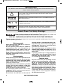
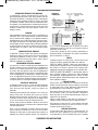
Safety Symbols
The definitions below describe the level of severity for each signal word. Please read the manual
and pay attention to these symbols.
!
This is the safety alert symbol. It is used to alert you to potential personal
injury hazards. Obey all safety messages that follow this symbol to avoid
possible injury or death.
DANGER indicates a hazardous situation which, if not avoided, will result in
death or serious injury.
WARNING indicates a hazardous situation which, if not avoided, could result
in death or serious injury.
CAUTION, used with the safety alert symbol, indicates a hazardous
situation which, if not avoided, will result in minor or moderate injury.
2610045250.qxp_GSB18V-535C 7/7/17 9:41 AM Page 2

SAVE THESE INSTRUCTIONS 3
Prevent unintentional starting. Ensure the
switch is in the off-position before connecting to
power source and / or battery pack, picking up
or carrying the tool. Carrying power tools with your
finger on the switch or energizing power tools that
have the switch on invites accidents.
Remove any adjusting key or wrench before
turning the power tool on. A wrench or a key left
attached to a rotating part of the power tool may
result in personal injury.
Do not overreach. Keep proper footing and
balance at all times. This enables better control of
the power tool in unexpected situations.
Dress properly. Do not wear loose clothing or
jewelry. Keep your hair, clothing and gloves
away from moving parts. Loose clothes, jewelry
or long hair can be caught in moving parts.
If devices are provided for the connection of
dust extraction and collection facilities, ensure
these are connected and properly used. Use of
dust collection can reduce dust-related hazards.
Do not let familiarity gained from frequent use
of tools allow you to become complacent and
ignore tool safety principles. A careless action
can cause severe injury within a fraction of a
second.
Power tool use and care
Do not force the power tool. Use the correct
power tool for your application. The correct
power tool will do the job better and safer at the
rate for which it was designed.
Do not use the power tool if the switch does not
turn it on and off. Any power tool that cannot be
controlled with the switch is dangerous and must
be repaired.
Disconnect the plug from the power source
and/or the battery pack from the power tool
before making any adjustments, changing
accessories, or storing power tools. Such
preventive safety measures reduce the risk of
starting the power tool accidentally.
Store idle power tools out of the reach of
children and do not allow persons unfamiliar
with the power tool or these instructions to
operate the power tool. Power tools are
dangerous in the hands of untrained users.
Maintain power tools. Check for misalignment or
binding of moving parts, breakage of parts and
any other condition that may affect the power
tool’s operation. If damaged, have the power tool
repaired before use. Many accidents are caused
by poorly maintained power tools.
Keep cutting tools sharp and clean. Properly
maintained cutting tools with sharp cutting edges
are less likely to bind and are easier to control.
Use the power tool, accessories and tool bits
etc. in accordance with these instructions, taking
into account the working conditions and the
work to be performed. Use of the power tool for
operations different from those intended could
result in a hazardous situation.
Battery tool use and care
Recharge only with the charger specified by
the manufacturer. A charger that is suitable for
one type of battery pack may create a risk of fire
when used with another battery pack.
Use power tools only with specifically
designated battery packs. Use of any other
battery packs may create a risk of injury and fire.
When battery pack is not in use, keep it away
from other metal objects like paper clips,
coins, keys, nails, screws, or other small
metal objects that can make a connection
from one terminal to another. Shorting the
battery terminals together may cause burns or a
fire.
Under abusive conditions, liquid may be
ejected from the battery; avoid contact. If
contact accidentally occurs, flush with water.
If liquid contacts eyes, additionally seek
medical help. Liquid ejected from the battery
may cause irritation or burns.
Do not use a battery pack or tool that is
damaged or modified. Damaged or modified
batteries may exhibit unpredictable behaviour
resulting in fire, EXPLOSION or risk of injury.
Do not expose a battery pack or tool to fire or
excessive temperature. Exposure to fire or
temperature above 265 °F (130 °C) may cause
explosion.
Follow all charging instructions and do not
charge the battery pack or tool outside the
temperature range specified in the
instructions. Charging improperly or at
temperatures outside the specified range may
damage the BATTERY and increase the risk of
fire.
Service
Have your power tool serviced by a qualified
repair person using only identical replacement
parts. This will ensure that the safety of the power
tool is maintained.
Never service damaged battery packs. Service
of battery packs should only be performed by the
manufacturer or authorized service providers.
2610045250.qxp_GSB18V-535C 7/7/17 9:41 AM Page 3

4 SAVE THESE INSTRUCTIONS
Safety Rules for Cordless Drill/Drivers
Wear ear protectors when impact drilling.
Exposure to noise can cause hearing loss.
Use auxiliary handle(s) if supplied with the
tool. Loss of control can cause personal injury.
Hold power tool by insulated gripping
surfaces, when performing an operation
where the cutting accessory may contact
hidden wiring. Cutting accessory contacting a
"live" wire may make exposed metal parts of the
power tool "live" and could give the operator an
electric shock.
Use clamps or another practical way to secure
and support the workpiece to a stable
platform. Holding the work by hand or against
your body leaves it unstable and may lead to loss
of control.
Do not drill, fasten or break into existing walls
or other blind areas where electrical wiring
may exist. If this situation is unavoidable,
disconnect all fuses or circuit breakers feeding this
worksite.
Always wear safety goggles or eye protection
when using this tool. Use a dust mask or
respirator for applications which generate
dust.
Use thick cushioned gloves and limit the
exposure time by taking frequent rest periods.
Vibration caused by hammer-drill action may be
harmful to your hands and arms.
Secure the material being drilled. Never hold it
in your hand or across legs. Unstable support
can cause the drill bit to bind causing loss of
control and injury.
Disconnect battery pack from tool before
making any assembly, adjustments or
changing accessories. Such preventive safety
measures reduce the risk of starting the tool
accidentally.
Position yourself to avoid being caught
between the tool or side handle and walls or
posts. Should the bit become bound or jammed
in the work, the reaction torque of the tool could
crush your hand or leg.
If the bit becomes bound in the workpiece,
release the trigger immediately, reverse the
direction of rotation and slowly squeeze the
trigger to back out the bit. Be ready for a strong
reaction torque. The drill body will tend to twist in
the opposite direction as the drill bit is rotating.
Do not grasp the tool or place your hands too
close to the spinning chuck or drill bit. Your
hand may be lacerated.
When installing a drill bit, insert the shank of
the bit well within the jaws of the chuck. If the
bit is not inserted deep enough, the grip of the
jaws over the bit is reduced and the loss of control
is increased.
Do not use dull or damaged bits and
accessories. Dull or damaged bits have a
greater tendency to bind in the workpiece.
When removing the bit from the tool avoid
contact with skin and use proper protective
gloves when grasping the bit or accessory.
Accessories may be hot after prolonged use.
Check to see that keys and adjusting
wrenches are removed from the drill before
switching the tool "ON". Keys or wrenches can
fly away at high velocity striking you or a
bystander.
Do not run the tool while carrying it at your
side. A spinning drill bit could become entangled
with clothing and injury may result.
Use auxiliary handle(s) if supplied with the
tool. Loss of control can cause personal injury.
Hold power tool by insulated gripping
surfaces, when performing an operation
where the cutting accessory may contact
hidden wiring. Cutting accessory contacting a
"live" wire may make exposed metal parts of the
power tool "live" and could give the operator an
electric shock.
Use clamps or another practical way to secure
and support the workpiece to a stable
platform. Holding the work by hand or against
your body leaves it unstable and may lead to loss
of control.
Do not drill, fasten or break into existing
walls or other blind areas where electrical
wiring may exist. If this situation is
unavoidable, disconnect all fuses or circuit
breakers feeding this worksite.
Always hold the tool with both hands. If the
bit jams two hands will give you maximum
control over torque reaction or kickback.
Safety Rules for Cordless Hammer Drills
2610045250.qxp_GSB18V-535C 7/7/17 9:41 AM Page 4

SAVE THESE INSTRUCTIONS 5
GFCI and personal protection devices like
electrician’s rubber gloves and footwear will
further enhance your personal safety.
Do not use AC only rated tools with a DC
power supply. While the tool may appear to
work, the electrical components of the AC rated
tool are likely to fail and create a hazard to the
operator.
Keep handles dry, clean and free from oil and
grease. Slippery hands cannot safely control the
power tool.
Develop a periodic maintenance schedule for
your tool. When cleaning a tool be careful not
to disassemble any portion of the tool since
internal wires may be misplaced or pinched or
safety guard return springs may be improperly
mounted. Certain cleaning agents such as
gasoline, carbon tetrachloride, ammonia, etc. may
damage plastic parts.
Ensure the switch is in the off position
before inserting battery pack. Inserting the
battery pack into power tools that have the
switch on invites accidents.
Some dust created by power
sanding, sawing, grinding,
drilling, and other construction activities
contains chemicals known to cause cancer,
birth defects or other reproductive harm.
Some examples of these chemicals are:
• Lead from lead-based paints,
• Crystalline silica from bricks and cement and
other masonry products, and
• Arsenic and chromium from chemically-
treated lumber.
Your risk from these exposures varies,
depending on how often you do this type of work.
To reduce your exposure to these chemicals:
work in a well ventilated area, and work with
approved safety equipment, such as those dust
masks that are specially designed to filter out
microscopic particles.
THINK SAFETY
SAFETY IS A COMBINATION OF OPERATOR
COMMON SENSE AND ALERTNESS AT ALL
TIMES WHEN POWER TOOLS ARE BEING
USED.
Additional Safety Warnings
Always wear safety goggles or eye
protection when using this tool. Use a dust
mask or respirator for applications which
generate dust.
Secure the material being drilled. Never hold
it in your hand or across legs. Unstable
support can cause the drill bit to bind causing
loss of control and injury.
Disconnect battery pack from tool or place
the switch in the locked or off position
before making any assembly, adjustments or
changing accessories. Such preventive safety
measures reduce the risk of starting the tool
accidentally.
Position yourself to avoid being caught
between the tool or side handle and walls or
posts. Should the bit become bound or
jammed in the work, the reaction torque of the
tool could crush your hand or leg.
If the bit becomes bound in the workpiece,
release the trigger immediately, reverse the
direction of rotation and slowly squeeze the
trigger to back out the bit. Be ready for a
strong reaction torque. The drill body will tend
to twist in the opposite direction as the drill bit is
rotating.
Do not grasp the tool or place your hands
too close to the spinning chuck or drill bit.
Your hand may be lacerated.
When installing a bit, insert the shank of the
bit well within the chuck. If the bit is not
inserted deep enough, the grip of the chuck over
the bit is reduced and the loss of control is
increased. After bit insertion, pull on bit to
ensure it is locked.
Do not use dull or damaged bits and
accessories. Dull or damaged bits have a
greater tendency to bind in the workpiece.
When removing the bit from the tool avoid
contact with skin and use proper protective
gloves when grasping the bit or accessory.
Accessories may be hot after prolonged use.
Check to see that keys and adjusting
wrenches are removed from the drill before
switching the tool "ON". Keys or wrenches
can fly away at high velocity striking you or a
bystander.
Do not run the drill while carrying it at your
side. A spinning drill bit could become
entangled with clothing and injury may result.
2610045250.qxp_GSB18V-535C 7/7/17 9:41 AM Page 5

6 SAVE THESE INSTRUCTIONS
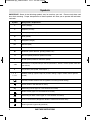
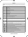
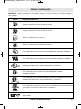
Symbols
IMPORTANT: Some of the following symbols may be used on your tool. Please study them and
learn their meaning. Proper interpretation of these symbols will allow you to operate the tool better
and safer.
Symbol Designation / Explanation
V Volts (voltage)
A Amperes (current)
Hz Hertz (frequency, cycles per second)
W Watt (power)
kg Kilograms (weight)
min Minutes (time)
s Seconds (time)
⌀
Diameter (size of drill bits, grinding wheels, etc.)
n
0
No load speed (rotational speed at no load)
n Rated speed (maximum attainable speed)
.../min
Revolutions or reciprocation per minute (revolutions, strokes, surface speed, orbits etc.
per minute)
0 Off position (zero speed, zero torque...)
1, 2, 3, ...
I, II, III,
Selector settings (speed, torque or position settings. Higher number means greater
speed)
0
Infinitely variable selector with off (speed is increasing from 0 setting)
Arrow (action in the direction of arrow)
Alternating current (type or a characteristic of current)
Direct current (type or a characteristic of current)
Alternating or direct current (type or a characteristic of current)
Class II construction (designates double insulated construction tools)
Earthing terminal (grounding terminal)
2610045250.qxp_GSB18V-535C 7/7/17 9:41 AM Page 6

SAVE THESE INSTRUCTIONS 7
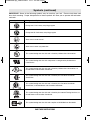
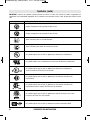
Symbols (continued)
IMPORTANT: Some of the following symbols may be used on your tool. Please study them and
learn their meaning. Proper interpretation of these symbols will allow you to operate the tool better
a
nd safer.
Symbol Designation / Explanation
Designates Li-ion battery recycling program
Designates Ni-Cad battery recycling program
Alerts user to read manual
Alerts user to wear eye protection
This symbol designates that this tool is listed by Underwriters Laboratories.
This symbol designates that this component is recognized by Underwriters
Laboratories.
This symbol designates that this tool is listed by Underwriters Laboratories, to
United States and Canadian Standards.
This symbol designates that this tool is listed by the Canadian Standards
Association.
This symbol designates that this tool is listed by the Canadian Standards
Association, to United States and Canadian Standards.
This symbol designates that this tool is listed by the Intertek Testing Services, to
United States and Canadian Standards.
This symbol designates that this tool complies to NOM Mexican Standards.
2610045250.qxp_GSB18V-535C 7/7/17 9:41 AM Page 7

8 SAVE THESE INSTRUCTIONS
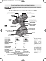
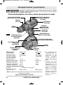
Functional Description and Specifications
Disconnect battery pack from tool before making any assembly, adjustments
or changing accessories. Such preventive safety measures reduce the risk of
starting the tool accidentally.
Cordless Drill Drivers and Cordless Hammer Drills
NOTE: For tool specifications refer to the nameplate on your tool.
Battery Packs/Chargers
Please refer to the Charger Manual included with your tool.
Model number GSR18V-535C GSB18V-535C
Voltage rating 18 V 18 V
No load speed 1 n
0
0-600/min n
0
0-600/min
No load speed 2 n
0
0-1900/min n
0
0-1900/min
Impact rate NA 0-22000 BPM
Maximum Capacities
Chuck size 1/2" 1/2"
Driving screw sizes #16 x 3" #16 x 3"
Drilling mild metal 1/2" 1/2"
Drilling hard wood 1-1/2" 1-1/2"
Drilling soft wood 2" 2"
Drilling Masonry NA 1/2"
Data Transmission (GCY30-4 installed)
Bluetooth® Bluetooth® 4.1 (Low Energy)
A
Signal interval, approx. 8 s 8 s
Signal range maximum 98ft
B
maximum 98ft
B
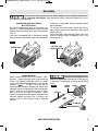
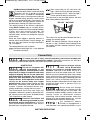
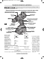
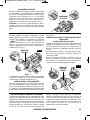
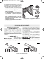
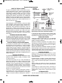
MODE SELECTOR RING
(Model GSB18V-535C only)
ADJUSTABLE
CLUTCH
KEYLESS
CHUCK
VARIABLE SPEED
TRIGGER SWITCH
BUILT IN WORK LIGHT AND
RED FUNCTION LIGHT
BATTERY PACK
RELEASE BUTTON
BATTERY PACK
VENTILATION
OPENINGS
FORWARD/REVERSING
LEVER AND TRIGGER LOCK
RUBBERIZED GRIP
GEAR SHIFTER /
SPEED RANGE SELECTOR
FIG. 1
CONNECTIVITY MODULE
COMPARTMENT
KICKBACK CONTROL
INSTRUCTION LABEL
BELT CLIP
A
The mobile terminal
devices must be
compatible with
Bluetooth® Low
Energy devices
(version 4.1) and
support the Generic
Access Profile (GAP).
B
The signal range may
vary greatly depending
on external conditions.
The Bluetooth® range
may be significantly
weaker inside closed
rooms and through
metallic barriers (e.g.
walls, shelving units,
cases, etc.).
2610045250.qxp_GSB18V-535C 7/7/17 9:41 AM Page 8

SAVE THESE INSTRUCTIONS 9
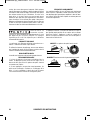
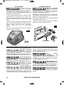
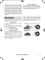
Assembly
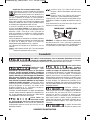
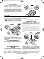
INSERTING BITS
Move reverse switch lever to the center “OFF”
position. Remove battery pack and rotate the
clutch ring (Model GSR18V-535C) or mode
selctor ring (Model GSB18V-535C) to the drill bit
symbol “ ”. To open rotate the chuck
sleeve counter-clockwise viewing from chuck end,
and open chuck to approximate drill bit diameter.
Insert a clean bit up to the drill bit flutes for small
bits, or as far as it will go for large bits. Close
chuck by rotating the chuck sleeve clockwise and
securely tighten by hand (Fig. 4). Return the
clutch ring or mode selector ring to desired
position.
Do not use the power of the
drill while grasping chuck to
loosen or tighten bit. Friction burn or hand injury
is possible if attempting to grasp the spinning
chuck.
CLOSE
OPEN
CHUCK
SLEEVE
FIG. 4
DRILL BIT
BIT HOLDER
SCREWDRIVER BIT
Disconnect battery pack from tool before making any assembly, adjustments
or changing accessories. Such preventive safety measures reduce the risk of
starting the tool accidentally.
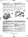
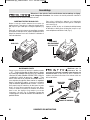
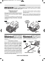
INSERTING AND RELEASING
BATTERY PACK
Set Forward/Reversing lever to the center (off
position). Slide charged battery pack into the
housing until the battery pack locks into position
(Fig. 2).
Your tool is equipped with a secondary locking
latch to prevent the battery pack from completely
falling out of the handle, should it become loose
due to vibration.
To remove the battery pack, press the battery
pack release button and slide the battery pack
forward (Fig. 3).
Press the battery pack release button again and
slide the battery pack completely out of tool
housing (Fig. 3).
BATTERY PACK
RELEASE BUTTON
FIG. 2 FIG. 3
BATTERY PACK
2610045250.qxp_GSB18V-535C 7/7/17 9:41 AM Page 9

10 SAVE THESE INSTRUCTIONS
BELT CLIP
When the tool is attached to
the belt, position yourself to
avoid entanglement with surrounding objects.
U
nexpected entanglement could cause the tool to
fall resulting in injury to the operator or bystanders.
The belt clip accessory will allow you to
conveniently attach your tool to your belt. This
feature will allow you to have both hands free
when climbing a ladder or moving to another work
area.
The belt clip can be attached to either side of the
tool by securing it with a mounting screw. Always
make sure you securely tighten the mounting
screw before use (Fig. 5).
To use clip, turn tool upside down and attach to
your belt.
4X BIT TIP HOLDER
Store only bit tips in the on-
tool bit holder. Longer bits
could interfere with proper tool operation and result
i
n user injury.
The four piece bit tip holder can be used for
convenient on tool storage of your most commonly
used bits.
When mounting bit holder accessory, mount on the
side of the drill opposite the belt clip.
Always make sure you securely tighten the
mounting screw before use. (Fig. 6).
BELT CLIP
FIG. 5
FIG. 6
BIT HOLDER
GCY30-4 CONNECTIVITY MODULE
INSTALLATION
To reduce the risk of injury
read the operating
instructions included with Bosch GCY30-4
connectivity module. Operating instructions for
GCY30-4 connectivity module include important
information not covered in this manual.
Only use Button/coin cell 3V
lithium CR2032 battery. Do
not use any other button/coin cells or other forms
of electrical power supply.
Ensure that battery
replacement is carried out
properly. There is a risk of explosion.
Chemical Burn Hazard.
Keep batteries away from
children. This product contains a lithium
button/coin cell battery. If a new or used lithium
button/coin cell battery is swallowed or enters the
body, it can cause severe internal burns and can
lead to death in as little as 2 hours. If you think a
battery might have been swallowed or placed
inside any part of the body, seek immediate
medical attention.
Always completely secure
the connectivity module
compartment. If the connectivity module
compartment does not close securely, stop using
the product, remove the battery, and keep it away
from children.
When discarding batteries,
insulate the ‘+’ and ‘–’
terminals with insulating tape. When disposed
of improperly, lithium batteries may short, causing
them to become hot, burst or ignite.
Never dispose of the
batteries in a fire or expose
to high heat. The batteries may explode.
2610045250.qxp_GSB18V-535C 7/7/17 9:41 AM Page 10

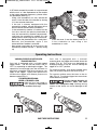
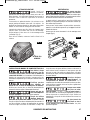
If GCY30-4 connectivity module is not purchased
with the tool, or if the replacement of the module
or the battery becomes necessary, please follow
this procedure (See Fig. 7):
- Using a flat screwdriver or a coin, remove the
cover 1 from the side of the handle, by turning
it 1/4 turn counter-clockwise.
- If the tool is already equipped with the
connectivity module, remove the battery 2, but
do not remove the connectivity module 3.
- If the connectivity module is installed for the
first time, remove the plastic placeholder 4
from the connectivity module compartment,
and place the connectivity module 3 in the
compartment observing correct orientation.
Note: Store the placeholder 4 in a safe place.
Reinsert the placeholder again if the
communications module is removed.
- Next place new battery 2 on the top of the
connectivity module with the “+” polarity facing
up.
- Place the cover 1 over the battery and turn it
¼-turn clockwise to lock using a flat
screwdriver or a coin.
SAVE THESE INSTRUCTIONS 11
VARIABLE SPEED CONTROLLED
TRIGGER SWITCH
Your tool is equipped with a variable speed
trigger switch. The tool can be turned "ON" or
"OFF" by squeezing or releasing the trigger. The
speed can be adjusted from the minimum to
maximum nameplate RPM by the pressure you
apply to the trigger. Apply more pressure to
increase the speed and release pressure to
decrease speed (Fig. 1).
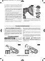
FORWARD/REVERSING
LEVER & TRIGGER LOCK
After tool use, lock trigger in
“OFF” position to help prevent
accidental starts and accidental discharge.
Your tool is equipped with a forward/
reversing lever and trigger lock located above the
trigger (Fig. 8). This lever was designed for
changing rotation of the bit, and for locking the
trigger in an “OFF” position.
For forward rotation, (with chuck pointed away
from you) move the lever to the far left (Fig. 8).
For reverse rotation move the lever to the far
right (Fig. 9). To activate trigger lock move lever
to the center off position.
Do not change direction of
rotation until the tool
comes to a complete stop. Shifting during
rotation of the chuck can cause damage to the
tool.
Operating Instructions
FIG. 8
FIG. 9
2
3
1
4
FIG. 7
2610045250.qxp_GSB18V-535C 7/7/17 9:41 AM Page 11

12 SAVE THESE INSTRUCTIONS
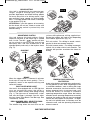
ADJUSTABLE CLUTCH
Your tool features 20 clutch settings. Output
torque will increase as the clutch ring, is rotated
from 1 to 20. The drill “ ” position will lock
up the clutch to permit drilling and driving
heavyduty work, and also enables bits to be
changed quickly and easily in the keyless chuck
(Fig. 11).
BRAKE
When the trigger switch is released it activates
the brake to stop the chuck quickly. This is
especially useful in the repetitive driving and
removal of screws.
BUILT IN LED WORK LIGHT
Your tool is also equipped with an LED light that
turns on automatically when the switch is
activated, for better visibility when drilling/ driving
(Fig. 1). The light turns off automatically a short
time after the trigger is released. You can adjust
this time frame using Bosch Tool Box app. See
“Connectivity” section.
DRILL/HAMMER DRILL SELECTOR RING
(Model GSB18V-535C only)
The selector ring allows the tool to be set for
various drilling/hammer drilling applications.
Rotate the selector dial right or left depending
on the below applications (Fig. 12).
Drill only action: For drilling in woods, metals,
plastics or other non concrete materials.
Drill with hammer action: For drilling in concrete,
asphalt, tile or other similar hard materials. The
hammer drill position overrides the clutch for
drilling.
TEMPERATURE OVERLOAD
PROTECTION
Avoid using battery operated tools continuously,
for long periods of time, while subjecting the tool
to overload conditions, such as drilling with large
diameter accessories into hard materials. Using
battery powered tools at extreme loads, may
cause the battery to exceed its allowable
operating temperature range. When the battery
exceeds normal operating temperature caused by
overload, the speed of the tool may be reduced
and the tool may appear to lose power. To regain
the tool's full performance, the battery must be
allowed to cool, until the operating temperature
returns to normal.
MODE
SELECTOR
RING
FIG. 12
ADJUSTABLE
CLUTCH
FIG. 11
GEAR SHIFTING
Your tool is equipped with two separate gear
ranges, low gear and high gear. Low gear
provides high-torque and slower drilling speeds
for heavy duty work or for driving screws. High
gear provides faster speeds for drilling lighter
work. To change speeds slide switch, to the high
or low position (Fig. 10).
ATTENTION: If your tool appears to be running,
but the chuck will not turn, check to make sure
the gear shifting switch is pushed fully into
desired setting.
GEAR
SHIFTER
FIG. 10
2610045250.qxp_GSB18V-535C 7/7/17 9:41 AM Page 12

SAVE THESE INSTRUCTIONS 13
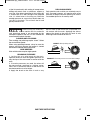
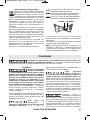
KickBack Control (Rapid Shut-off)
To ensure better control of the tool during
operation, this tool is design to shut-off
while in use if a sudden or unexpected
bind up situation occurs. Bind up occurs when the
bit gets jammed during operation, which forces
the bit to stop spinning abruptly. If this occurs, the
tool will shut down and the KickBack Control will
be indicated by flashing LED lights on the tool.
The sensitivity level of this feature is adjustable.
Using Bosch Toolbox app on a mobile device,
operator may select one of three settings between
“Earlier” and “Later” markers on the app. The
settings only control the KickBack Control
activation delay, and do not change the capacity
of this feature.
When the switch trigger is pressed, operator is
notified about the KickBack Control settings, by
the work light and function red light identified in
Fig. 1 on page 8.
The setting indications are as follows:
Continuous white light (W) = Later (delayed
Kick Back activation).
Slow alternating red (R) and white (W)
light = Mid-Level (less delayed activation).
Fast alternating red (R) / white (W) light =
Earlier (minimum delay to activation).
The label next to the work light displays the Kick
Back setting indicator light pattern.
This feature can only be activated when the tool is
running at maximum speed.
NOTE: The default KickBack Control setting for
the tool is “Later”. KickBack Control setting for the
tool without GCY30-4 module installed is always
set to default.
W
WR WR
WWWW
R
RRR
RED LIGHT WHITE LIGHT
Connectivity
BLUETOOTH®
Do not use the power tool
with Bluetooth® in the
vicinity of gas stations, chemical plants, areas
where there is danger of explosion and areas
subject to blasting. Do not use the power tool
with Bluetooth® in airplanes. Do not use the
power tool with Bluetooth® in the vicinity of
medical devices. Avoid operation in the direct
vicinity of the human body over longer
periods of time. When using the power tool with
Bluetooth®, interference with other devices and
systems, airplanes and medical devices (e.g.,
cardiac pacemakers, hearing aids) may occur.
The Bluetooth® word mark and logos are
registered trademarks owned by Bluetooth SIG,
Inc. and any use of such marks by Robert Bosch
Tool Corporation is under license.
Follow all instructions and
warnings provided by your
Bluetooth® device manufacturer. Failure to
follow recommended procedures could result in
personal injury or property damage.
Exercise extreme caution
when using Bluetooth®
devices to control or change power tool
functions. Operation of the device may be in a
different area than the paired power tool. Paired
devices may have functionality which allows timed
event programming, including automatically
powering on (e.g. flood light). Depending upon the
power tool, these unattended operations or
function changes without direct line of sight to the
paired tool could result in personal injury or
property damage.
Always check tool settings
before use. Settings may be
different than when the tool was last used. The
connectivity module enables transfer of data and
settings based on Bluetooth® wireless
technology. With module installed, select tool
settings may be changed remotely by a paired
Bluetooth® device and user installed app.
The connectivity module
GCY30-4 is equipped with a
radio interface. Local operating restrictions, e.g. in
To reduce the risk of injury read the operating instructions included with
Bosch GCY30-4 connectivity module. Operating instructions for GCY30-4
connectivity module include important information not covered in this manual.
2610045250.qxp_GSB18V-535C 7/7/17 9:41 AM Page 13

military sites or hospitals, are to be observed.
Transmitters have demonstrated an ability to
unintentionally interfere with other devices.
THINK SAFETY
SAFETY IS A COMBINATION OF OPERATOR
COMMON SENSE AND ALERTNESS AT ALL
TIMES WHEN THE TOOL IS BEING USED.
FCC Caution
The manufacturer is not responsible for radio
interference caused by unauthorized modifications
to this equipment. Such modifications could void
the user’s authority to operate the equipment.
This device complies with Part 15 of the FCC
Rules. Operation is subject to the following two
conditions:
1) This device may not cause harmful
interference, and
2) This device must accept any interference
received, including interference that may cause
undesired operation.
NOTE! This equipment has been tested and
found to comply with the limits for a Class B digital
devices, pursuant to Part 15 of the FCC rules.
These limits are designed to provide reasonable
protection against harmful interference in a
residential installation. This equipment generates,
uses and can radiate radio frequency energy and,
if not installed and used in accordance with the
instructions, may cause harmful interference to
radio communications. However, there is no
guarantee that interference will not occur in a
particular installation. If this equipment does
cause harmful interference to radio or television
reception, which can be determined by turning the
equipment off and on, the user is encouraged to
try to correct the interference by one or more of
the following measures:
• Reorient or relocate the receiving antenna.
• Increase the separation between the
equipment and receiver.
• Connect the equipment into an outlet on a
c
ircuit different from that to which the receiver
is connected.
• Consult the dealer or an experienced radio/TV
technician for help.
“Exposure to Radio Frequency (RF) Signals: The
wireless device is a radio transmitter and receiver.
It is designed and manufactured not to exceed the
emission limit for exposure to radio frequency
(RF) energy set by the Ministry of Health
(Canada), Safety Code 6. These limits are part of
comprehensive guidelines and established
permitted levels of RF energy for the general
population.
These guidelines are based on the safety
standards previously set by international standard
bodies. These standards include a substantial
safety margin designed to assure the safety of all
persons, regardless of age and health.
This device and its antenna must not be co-
located or operating in conjunction with any other
antenna or transmitter.
Industry Canada
This device complies with Industry Canada
licence-exempt RSS standard(s). Operation is
subject to the following two conditions:
(1) this device may not cause interference, and
(2) this device must accept any interference,
including interference that may cause undesired
operation of the device.
14 SAVE THESE INSTRUCTIONS
2610045250.qxp_GSB18V-535C 7/7/17 9:41 AM Page 14

SAVE THESE INSTRUCTIONS 15
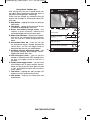
Using ‘Bosch Toolbox’ app
After pairing your tool with a mobile device you
can adjust certain functions or check the status of
the power tool using Bosch Toolbox app.
Every time you change any setting the tool will
confirm the changes by flashing the white LED
work light.
A. Help button – tapping this button will bring up
help screen.
B. Tool photo – tapping on the photo will let you
customize the photograph of the tool.
C. Power tool battery charge status – the
number of green ‘batteries’ indicates the
estimated charge level for the battery pack.
D. Power tool nickname – tapping on the ‘pencil’
icon will let you customize the tool nickname.
You can also do it when changing the tool
photo.
E. Connection status bar – Here you can see
the connection (signal) strength indicated by
vertical bars. You can use toggle switch to
disconnect the tool from you mobile device.
F. KickBack Control adjustment slide – you
can choose between three settings: ‘Earlier’,
Middle (unmarked) and ‘Later’.
G. LED Afterglow timer – you can set the
number of second that the LED worklight stays
on after the trigger switch of the tool is
released.
H. Factory Reset toggle switch – you can reset
tool settings back to factory default settings.
When you do so the LED after glow will reset
to ‘10s’ and KickBack Control will be reset to
‘Later’ setting.
I. Tool alerts – tapping the ‘alerts triangle’ will
display any alerts received from the tool.
J. Info button – displays tool information and
specifications.
GSB18V-535C
Connected
LED Afterglow
Reset to Factory Default
KickBack Control
10s
(Activation)
E
arlier Later
GSB18V-535C
?
A
B
C
D
E
F
G
H
IJ
2610045250.qxp_GSB18V-535C 7/7/17 9:41 AM Page 15

16 SAVE THESE INSTRUCTIONS
DRIVING NUTS AND BOLTS
Variable speed control must be used with caution
for driving nuts and bolts with socket set attach -
ments. The technique is to start slowly, increasing
speed as the nut or bolt runs down. Set the nut or
bolt snugly by slowing the drill to a stop. If this
procedure is not followed, the tool will have a
tendency to torque or twist in your hands when the
nut or bolt seats.
DRILLING
You will extend the life of your bits and do neater
work if you always put the bit in contact with the
work before pulling the trigger. During the oper a -
tion, hold the tool firmly and exert light, steady
pressure. Too much pressure at low speed will
stall the tool. Too little pressure will keep the bit
from cutting and cause excess friction by sliding
over the surface. This can be damaging to both
tool and bit.
DRILLING WITH VARIABLE SPEED
The variable speed trigger allows you to slowly
increase RPM. By using a slow starting speed, you
are able to keep the bit from “wander ing”. You can
increase the speed as the bit “bites” into the work
by squeezing the trigger.
DRIVING WITH VARIABLE SPEED
Variable speed drills will double as a power
screwdriver by using a screwdriver bit. Prior to
driving screws, pilot and clearance holes should be
drilled. Place the threaded end of the screw in the
pilot or clearance hole and start driving the screw
slowly, increasing the speed as the screw runs
down. Set the screw snugly by slowing to a stop.
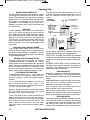
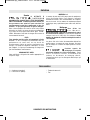
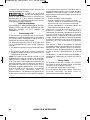
FASTENING WITH SCREWS
The procedure shown in Fig. 13 will enable you
to fasten materials together using your drill
without stripping, splitting or separating the
material.
First, clamp the pieces together and drill the
hole 2/3 the diameter of the screw. If the
material is soft, drill only 2/3 the proper length. If
it is hard, drill the entire length.
Second, unclamp the pieces and drill the hole in
the top piece of wood again to the same
diameter as the shank of the screw.
Third, if flat head screw is used, countersink the
hole to make the screw flush with the surface.
Realign the holes on the two pieces and apply
even pressure when driving the screw. The
screw shank clearance hole in the first piece
allows the screw head to pull the pieces tightly
together.
The adjustable screw drill accessory will do all
of these operations quickly and easily. Screw
drills are available for screw sizes No. 6, 8, 10
and 12.
DRILL BITS
Always inspect drill bits for excessive wear. Use
only bits that are sharp and in good condition.
TWIST BITS: Available with straight and reduced
shanks for wood and light duty metal drilling. High
speed bits cut faster and last longer on hard ma -
terials.
CARBIDE TIPPED BITS: Used for drilling stone,
con crete, plaster, cement and other unusually hard
nonmetals. Use continuous heavy feed pres sure
when employing carbide tip bits.
DRILLING WOOD
Be certain workpiece is clamped or anchored firm -
ly. Always apply pressure in a straight line with the
drill bit. Maintain enough pressure to keep the drill
“biting”.
When drilling holes in wood, twist bits can be used.
Twist bits may overheat unless pulled out
frequently to clear chips from flutes.
Use a “back-up” block of wood for work that is
likely to splinter, such as thin materials.
You will drill a cleaner hole if you ease up on the
pressure just before the bit breaks through the
wood. Then complete the hole from the back side.
DRILLING METAL
There are two rules for drilling hard materials. First,
the harder the material, the greater the pres sure
you need to apply to the tool. Second, the harder
the material, the slower the speed. Here are a
couple of tips for drilling in metal. Lubri cate the tip
Operating Tips
2
. Drill same diameter
as screw shank
3. Countersink
same diameter
a
s screw head
1. Drill 2/3 diameter
and 2/3 of screw
l
ength for soft
materials, full
length for hard
materials
Screw
A
pply a slight
e
ven pressure
w
hen driving
s
crews
A
djustable
S
crew
D
rill
Top
B
ottom
F
ASTENING
W
ITH SCREWS
FIG. 13
2610045250.qxp_GSB18V-535C 7/7/17 9:41 AM Page 16

SAVE THESE INSTRUCTIONS 17
Before using an accessory,
be certain that its maximum
safe operating speed is not exceeded by the
nameplate speed of the tool. Do not exceed the
recommended wheel diameter.
SANDING AND POLISHING
Fine sanding and polishing re quire “touch”. Select
the most efficient speed.
When using polishing bonnets, alway be sure the
excess string that secures the bonnet is tucked
well within the bonnet during operation.
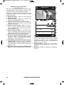
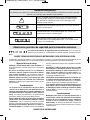
WIRE BRUSHES
Work with brushes requires high speeds.
BRUSHING PRESSURE
1. Let the tips of a wire brush do the work.
Operate the brush with the lightest pressure so
only the tips of the wire come in contact with the
work.
2. If heavier pressures are used, the wires will
be overstressed, resulting in a wiping action;
and if this is continued, the life of the brush will
be shortened due to wire fatigue.
3. Apply the brush to the work in such a way
that as much of the brush face as possible is in
full contact with the work. Applying the side or
edge of the brush to the work will result in wire
breakage and shortened brush life.
CORRECT: Wire tips doing the work.
INCORRECT: Excessive pressure can cause wire breakage.
of the bit occasionally with cutting oil except when
drilling soft metals such as alu minum, cop per or
cast iron. If the hole to be drilled is fairly large, drill
a smaller hole first, then enlarge to the required
size, it’s often faster in the long run. Main tain
enough pressure to assure that the bit does not
just spin in the hole. This will dull the bit and
greatly shorten its life.
DRILLING MASONRY
Soft materials such as brick are relatively easy to
drill. Concrete however, will require much more
pressure to keep the bit from spinning. Be sure to
use carbide tip bits for all masonry work.
2610045250.qxp_GSB18V-535C 7/7/17 9:41 AM Page 17

18 SAVE THESE INSTRUCTIONS
(* = standard equipment)
(** = optional accessories)
* Screwdriver bit
* Carrying case
Accessories
Service
NO USER SERVICEABLE
PARTS INSIDE. Preventive
maintenance performed by un au thorized
personnel may result in misplacing of
internal wires and components which could
cause serious hazard. We recom mend that all
tool service be performed by a Bosch Factory
Service Center or Authorized Bosch Service
Station. SERVICE MEN: Disconnect tool and/or
charger from power source before servicing.
BATTERIES
Be alert for battery packs that are nearing
their end of life. If you notice decreased tool
performance or significantly shorter running time
between charges then it is time to replace the
battery pack. Failure to do so can cause the
tool to operate improperly or damage the
charger.
TOOL LUBRICATION
Your Bosch tool has been properly lubricated
and is ready for use.
D.C. MOTORS
The motor in your tool has been engineered for
many hours of dependable service. To maintain
peak efficiency of the motor, we recommend it
be examined every six months. Only a genuine
Bosch replacement motor specially designed for
your tool should be used.
Cleaning
To avoid accidents, always
disconnect the tool and/or
charger from the power supply before
cleaning. The tool may be cleaned most
effectively with com pressed dry air. Always
wear safety goggles when cleaning tools
with compressed air.
Ventilation openings and switch levers must be
kept clean and free of foreign matter. Do not
attempt to clean by inserting pointed objects
through opening.
Certain cleaning agents
and solvents damage
plastic parts. Some of these are: gasoline, car -
bon tetrachloride, chlorinated cleaning solvents,
ammonia and household detergents that contain
ammonia.
Maintenance
2610045250.qxp_GSB18V-535C 7/7/17 9:41 AM Page 18

CONSERVEZ CES INSTRUCTIONS 19
Veuillez lire tous les avertissements et toutes les consignes de sécurité. Si l'on
n'observe pas ces avertissements et ces consignes de sécurité, il existe un risque de
choc électrique, d'incendie et/ou de blessures corporelles graves.
CONSERVEZ TOUS LES AVERTISSEMENTS ET TOUTES LES CONSIGNES
DE SÉCURITÉ POUR RÉFÉRENCE FUTURE.
Dans les avertissements, le terme « outil électroportatif » se rapporte à votre outil branché sur le secteur (avec fil) ou à votre
outil alimenté par piles (sans fil).
Avertissements généraux concernant la sécurité des outils électroportatifs
Sécurité du lieu de travail
Maintenez le lieu de travail propre et bien éclairé. Les
risques d’accident sont plus élevés quand on travaille dans
un endroit encombré ou sombre.
N’utilisez pas d’outils électroportatifs dans des
atmosphères explosives, comme par exemple en
présence de gaz, de poussières ou de liquides
inflammables. Les outils électroportatifs produisent des
étincelles qui risquent d’enflammer les poussières ou les
vapeurs.
Éloignez les enfants et les visiteurs quand vous vous
servez d’un outil électroportatif. Vous risquez une perte
de contrôle si on vous distrait.
Sécurité électrique
Les fiches des outils électroportatifs doivent
correspondre à la prise. Il ne faut absolument jamais
modifier la fiche. N’utilisez pas d’adaptateur de prise
avec des outils électroportatifs munis d’une fiche de
terre. Le risque de choc électrique est moindre si on utilise
une fiche non modifiée sur une prise qui lui correspond.
Évitez tout contact du corps avec des surfaces reliées à la
terre tels que tuyaux, radiateurs, gazinières ou
réfrigérateurs. Le risque de choc électrique augmente si
votre corps est relié à la terre.
N’exposez pas les outils électroportatifs à la pluie ou à
l’humidité. Si de l’eau pénètre dans un outil électroportatif,
le risque de choc électrique augmente.
Ne maltraitez pas le cordon. Ne vous en servez jamais
pour transporter l’outil électroportatif, pour le tirer ou
pour le débrancher. Éloignez le cordon de la chaleur, des
huiles, des arêtes coupantes ou des pièces mobiles. Les
cordons abîmés ou emmêlés augmentent les risques de
choc électrique.
Si vous utilisez un outil électroportatif à l’extérieur,
employez une rallonge conçue pour l’extérieur. Ces
rallonges sont faites pour l’extérieur et réduisent le risque
de choc électrique.
S'il est absolument nécessaire d'utiliser l'outil
électroportatif dans un endroit humide, utilisez une
alimentation protégée par un disjoncteur de fuite de terre
(GFCI). L'utilisation d'un disjoncteur GFCI réduit les risques
de choc électrique.
Sécurité personnelle
Restez concentré, faites attention à ce que vous faites, et
servez-vous de votre bon sens lorsque vous utilisez un
outil électroportatif. N'employez pas d’outils
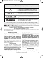
Symboles relatifs à la sécurité
Les définitions ci-dessous décrivent le niveau de gravité pour chaque terme signalant un danger. Veuillez lire le mode
d’emploi et lire la signification de ces symboles.
!
C’est le symbole d’alerte relatif à la sécurité. Il est utilisé pour vous avertir
de l’existence possible d’un danger de lésion corporelle. Obéissez à tous
les messages relatifs à la sécurité qui suivent ce symbole pour éviter tout
risque de blessure ou même de mort.
DANGER indique une situation dangereuse qui, si elle n’est pas évitée,
causera la mort d’une personne ou une blessure grave.
AVERTISSEMENT indique une situation dangereuse qui, si elle n’est
pas évitée, pourrait causer la mort d’une personne ou une blessure
grave.
MISE EN GARDE, conjointement avec le symbole d’alerte en liaison
avec la sécurité, indique une situation dangereuse qui, si elle n'est pas
évitée, causera une blessure légère ou modérée.
2610045250.qxp_GSB18V-535C 7/7/17 9:41 AM Page 19

20 CONSERVEZ CES INSTRUCTIONS
électroportatifs quand vous êtes fatigué ou sous l’emprise
de drogues, d’alcool ou de médicaments. Quand on utilise
des outils électroportatifs, il suffit d’un moment
d’inattention pour causer des blessures corporelles graves.
Utilisez des équipements de sécurité personnelle. Portez
toujours une protection oculaire. Le port d'équipements de
sécurité tels que des masques antipoussières, des
chaussures de sécurité antidérapantes, des casques de
chantier et des protecteurs d'oreilles dans des conditions
appropriées réduira le risque de blessure corporelle.
Évitez les démarrages intempestifs. Assurez-vous que
l'interrupteur est dans la position arrêt (Off) avant de
brancher l'outil dans une prise de courant et/ou un bloc-
piles, de le ramasser ou de le transporter. Le transport
d'un outil électroportatif avec le doigt sur la gâchette ou le
branchement de cet outil quand l'interrupteur est en
position de marche (ON) est une invite aux accidents.
Enlevez toutes les clés de réglage avant de mettre l’outil
électroportatif en marche. Si on laisse une clé sur une
pièce tournante de l’outil électroportatif, il y a risque de
blessure corporelle.
Ne vous penchez pas. Conservez toujours une bonne
assise et un bon équilibre. Ceci vous permettra de mieux
maîtriser l’outil électroportatif dans des situations
inattendues.
Habillez-vous de manière appropriée. Ne portez pas de
vêtements amples ou de bijoux. Attachez les cheveux
longs. N’approchez pas les cheveux, les vêtements ou
les gants des pièces en mouvement. Les vêtements
amples, les bijoux ou les cheveux longs risquent d’être
happés par les pièces en mouvement.
Si l’outil est muni de dispositifs permettant le
raccordement d’un système d’aspiration et de collecte
des poussières, assurez-vous que ces dispositifs sont
raccordés et utilisés correctement. L'utilisation d'un
dépoussiéreur peut réduire les dangers associés à
l'accumulation de poussière.
Ne laissez pas la familiarité résultant de l'utilisation
fréquente des outils vous inciter à devenir complaisant(e)
et à ignorer les principes de sécurité des outils. Une
action négligente pourrait causer des blessures graves en
une fraction de seconde.
Utilisation et entretien des
outils électroportatifs
Ne forcez pas sur l’outil électroportatif. Utilisez l’outil
électroportatif qui convient à la tâche à effectuer. L’outil
qui convient à la tâche fait un meilleur travail et est plus sûr
à la vitesse pour lequel il a été conçu.
Ne vous servez pas de l’outil électroportatif si son
interrupteur ne parvient pas à le mettre en marche ou à
l’arrêter. Tout outil électroportatif qui ne peut pas être
commandé par son interrupteur est dangereux et doit être
réparé.
Débranchez la fiche de la prise ou enlevez le bloc-pile de
l’outil électroportatif avant tout réglage, changement
d’accessoires ou avant de ranger l’outil électroportatif.
De telles mesures de sécurité préventive réduisent le risque
de démarrage intempestif de l’outil électroportatif.
Rangez les outils électroportatifs dont vous ne vous
servez pas hors de portée des enfants et ne permettez pas
à des personnes qui ne connaissent pas l’outil
électroportatif ou qui ignorent ces consignes de s’en
servir. Les outils électroportatifs sont dangereux dans les
mains d’utilisateurs inexpérimentés.
Entretenez les outils électroportatifs. Vérifiez que les
pièces mobiles sont alignées correctement et ne coincent
pas. Vérifiez qu’il n’y a pas de pièces cassées ou d’autre
circonstance qui risquent d’affecter le fonctionnement de
l’outil électroportatif. Si l’outil est abîmé, faites-le
réparer avant de l’utiliser. De nombreux accidents sont
causés par des outils électroportatifs mal entretenus.
Maintenez les outils coupants affûtés et propres. Les
outils coupants entretenus correctement et dotés de bords
tranchants affûtés sont moins susceptibles de coincer et
sont plus faciles à maîtriser.
Utilisez l'outil électroportatif, les accessoires et les
embouts d'outil, etc. conformément à ces instructions, en
tenant compte des conditions de travail et des travaux à
réaliser. L'emploi d’outils électroportatifs pour des tâches
différentes de celles pour lesquelles ils ont été prévus peut
résulter en une situation dangereuse.
Utilisation et entretien des outils à piles
Rechargez les piles uniquement avec le chargeur spécifié
par le fabriquant. Un chargeur qui convient à un type de
bloc-piles peut entraîner un risque d’incendie quand il est
utilisé avec un autre bloc-piles.
Utilisez des outils électroportatifs uniquement avec les
bloc-piles spécifiquement désignés pour eux. L’utilisation
de tout autre bloc-piles peut créer un risque de blessures et
d’incendie.
Lorsque le bloc-piles n’est pas utilisé, gardez-le à
distances d’autres objets métalliques tels que des
trombones, des pièces de monnaie, des clés, des clous,
des vis ou de tout autre objet métallique pouvant faire
une connexion entre une borne et une autre. Court-
circuiter les bornes des piles peut causer des brûlures ou
un incendie.
Dans des conditions abusives, du liquide peut être éjecté
de la pile ; dans un tel cas, évitez tout contact avec ce
liquide. Si un contact se produit accidentellement, rincez
avec de l’eau. Si le liquide entre en contact avec les
yeux, consultez un médecin. Du liquide éjecté de la pile
peut causer des irritations ou des brûlures.
N’utilisez pas un bloc-piles ou un outil qui est
endommagé ou a été modifié. Des piles endommagées ou
modifiées peuvent se comporter de façon imprévisible et
causer un incendie ou une EXPLOSION pouvant entraîner
des blessures.
N’exposez pas un bloc-piles ou un outil à un incendie ou
à une température excessive. L’exposition à un incendie
ou à une température supérieure à 265° F (130° C) pourrait
causer une explosion.
Suivez toutes les instructions relatives à la charge et ne
chargez pas le bloc-piles ou l’outil en dehors de la plage
2610045250.qxp_GSB18V-535C 7/7/17 9:41 AM Page 20
La page charge ...
La page charge ...
La page charge ...
La page charge ...
La page charge ...
La page charge ...
La page charge ...
La page charge ...
La page charge ...
La page charge ...
La page charge ...
La page charge ...
La page charge ...
La page charge ...
La page charge ...
La page charge ...
La page charge ...
La page charge ...
La page charge ...
La page charge ...
La page charge ...
La page charge ...
La page charge ...
La page charge ...
La page charge ...
La page charge ...
La page charge ...
La page charge ...
La page charge ...
La page charge ...
La page charge ...
La page charge ...
La page charge ...
La page charge ...
La page charge ...
La page charge ...
-
 1
1
-
 2
2
-
 3
3
-
 4
4
-
 5
5
-
 6
6
-
 7
7
-
 8
8
-
 9
9
-
 10
10
-
 11
11
-
 12
12
-
 13
13
-
 14
14
-
 15
15
-
 16
16
-
 17
17
-
 18
18
-
 19
19
-
 20
20
-
 21
21
-
 22
22
-
 23
23
-
 24
24
-
 25
25
-
 26
26
-
 27
27
-
 28
28
-
 29
29
-
 30
30
-
 31
31
-
 32
32
-
 33
33
-
 34
34
-
 35
35
-
 36
36
-
 37
37
-
 38
38
-
 39
39
-
 40
40
-
 41
41
-
 42
42
-
 43
43
-
 44
44
-
 45
45
-
 46
46
-
 47
47
-
 48
48
-
 49
49
-
 50
50
-
 51
51
-
 52
52
-
 53
53
-
 54
54
-
 55
55
-
 56
56


Bosch GSB18V-535CB15 Manuel utilisateur
- Catégorie
- Marteaux rotatifs
- Taper
- Manuel utilisateur
dans d''autres langues
- English: Bosch GSB18V-535CB15 User manual
- español: Bosch GSB18V-535CB15 Manual de usuario
Documents connexes
-
Bosch GSB18V-1330CB14 Mode d'emploi
-
 Bosch Tools GDX18V-1800CB25 Le manuel du propriétaire
-
Bosch Power Tools HDS182-01L Manuel utilisateur
-
-
Bosch HDS183 Manuel utilisateur
-
Bosch Power Tools HDS181A-02 Manuel utilisateur
-
Bosch Power Tools PS22-02 Manuel utilisateur
-
-
-
