Pacific energy ALDERLEA T5 LE Manuel utilisateur
- Catégorie
- Poêles
- Taper
- Manuel utilisateur
Ce manuel convient également à

140623-28 ALT5-LE 100000353
OPERATING AND
INSTALLATION
INSTRUCTIONS
SAFETY NOTICE
If this stove is not properly installed, a
house re may result. For your safety,
follow the installation instructions.
Contact local building or re ofcials
about restrictions and installation
inspection requirements in your area.
TESTED and LISTED to;
CAN/ULC S627 AND UL 1482
IMPORTANT:
THESE INSTRUCTIONS ARE TO
REMAIN WITH THE HOMEOWNER
MODEL:
ALDERLEA T5 LE
SERIAL #
Visit www.pacificenergy.net for the most recent version of this manual
Meets the U.S. Environmental Protection
Agency's 2020 Particulate Emission Standards
(Crib Wood).

Experience will give you the right settings for proper combustion and efcient burning. Remember the correct air inlet
setting is affected by variables such as type of wood, outside temperature, chimney size and weather conditions. With
practice, you will become procient in operating your heater and will obtain the performance for which it was designed.
Table of Contents
HOT GLASS WILL CAUSE
BURNS.
DO NOT TOUCH GLASS UNTIL
COOLED.
NEVER ALLOW CHILDREN TO
TOUCH GLASS.
!
WARNING
PLEASE SAVE THESE INSTRUCTIONS
NOTE: WE STRONGLY RECOMMEND THAT SMOKE AND CARBON MONOXIDE DETECTORS BE INSTALLED IN
THE AREA WHERE THE HEATER IS TO BE INSTALLED.
If smoke detectors have been previously installed, you may notice that they are operating more frequently. This may be
due to curing of stove paint or fumes caused by accidentally leaving the re door open. Do not disconnect the detectors.
SAFETY NOTICE: If this stove is not properly installed, a house fire may result. For your safety, follow the
installation instructions. Contact local building or fire officials about restrictions and installation inspection
requirements in you area.
Please read this entire manual before you install and use your new room heater. Failure to follow instructions may result
in property damage, bodily injury, or even death.
Contents
Table of Contents ...................................................................... 2
Rating Label .............................................................................. 3
Efciency and BTU Output ................................................. 3
Safety ........................................................................................ 4
Chimney Smoke and Creosote Formation ......................... 4
Chimney Fires .................................................................... 4
To Avoid a Chimney Fire..................................................... 5
In the event of a Chimney Fire ........................................... 5
Curing of the Paint Finish ................................................... 5
Operation ................................................................................... 6
Wood Selection .................................................................. 6
DO NOT BURN : ................................................................. 6
How to Test Your Wood ...................................................... 6
Lighting a re ...................................................................... 7
Normal Operation ............................................................... 7
Restarting After Extended or Overnight Burns .................. 8
Proper Draft ........................................................................ 8
Ash Removal ...................................................................... 8
Ash Clean out system: ..................................................... 8
Disposal of Ashes............................................................... 8
Maintenance .............................................................................. 9
Maintenance Checks ............................................................... 10
Weekly: ............................................................................. 10
Monthly ............................................................................ 10
When Cleaning the Chimney System: .............................. 10
Blower: ............................................................................. 10
Bafe: ............................................................................... 10
Bafe Removal ........................................................................ 10
Assembly ................................................................................. 11
Dimensions .............................................................................. 11
Floor Protector ........................................................................ 12
Residential Installation ............................................................. 13
Clearances: ...................................................................... 13
Chimney and Connector .................................................. 14
When using a Double-Wall Connector ............................. 14
When using a Single-Wall (smoke pipe) Connector ......... 14
Installation Procedure ...................................................... 15
Combustion Air ........................................................................ 15
Through Wall Installations (as per NFPA 211) ................. 18
Optional Blower ....................................................................... 20
Blower Operation ............................................................. 20
Mobile Home Installation ......................................................... 20
Trouble Shooting ..................................................................... 22
Firebrick Installation ................................................................ 23
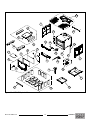
Parts Diagram - Alderlea T5 LE ................................................ 26
ALT 5-LE 140623-28
2
100000353

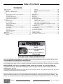
CERTIFIED FOR CANADA AND U.S.A. - MODEL / MODÈLE: SUPER LE SUPER CLASSIC LE ALDERLEA T5 LE
LISTED ROOM HEATER, SOLID FUEL TYPE. ALSO FOR USE IN MOBILE HOMES.
CERTIFIED TO/ CERTIFIÉ POUR : CAN/ULC S627 / UL 1482
Refer to Intertek’s Directory of Building Products for detailed information
ADJACENT WALL
BACK WALL
D
A
SIDE WALL
BE
ADJACENT WALL
F
C
MUR COTE
MUR ARRIERE
MUR ADJACENT
MUR ADJACENT
A.
14 in. / 356 mm
B.
8 in. / 152 mm
C.
7 in. / 178 mm
SUPER
D.
23 in. / 585 mm
E.
15 in. / 380 mm
F.
18 in. / 460 mm
ALDERLEA T5
D.
23.5 in. / 595 mm
E.
15 in. / 380 mm
F.
21 in. / 535 mm
• INSTALL AND USE IN ACCORDANCE WITH THE MANUFACTURER’S INSTALLATION AND OPERATING
INSTRUCTIONS.
• CONTACT LOCAL BUILDING OR FIRE OFFICIALS ABOUT RESTRICTIONS, INSTALLATION PERMIT AND
INSPECTION IN YOUR AREA.
• DO NOT CONNECT THIS UNIT TO A CHIMNEY FLUE SERVING ANOTHER APPLIANCE (USA. ONLY).
• USE 6 INCH / 150MM DIAMETER MINIMUM 24 MSG BLACK OR LISTED CONNECTOR.
• CAN BE CONNECTED TO A LINED MASONRY CHIMNEY SUITABLE FOR USE WITH SOLID FUELS.
• DO NOT OBSTRUCT THE SPACE BENEATH THE HEATER.
• SEE LOCAL BUILDING CODE AND MANUFACTURER'S INSTRUCTIONS FOR PRECAUTIONS REQUIRED
WHEN PASSING A CHIMNEY THROUGH A COMBUSTIBLE WALL OR CEILING.
• DO NOT PASS A CHIMNEY CONNECTOR THROUGH A COMBUSTIBLE WALL OR CEILING.
• MINIMUM CLEARANCE BETWEEN SINGLE WALL CHIMNEY CONNECTOR AND COMBUSTIBLE
MATERIALS-18INCHES/455MM. CLEARANCE MAY BE REDUCED BY THE USE OF LISTED PIPE
SHIELDS, WALL PROTECTORS OR OTHER MEANS APPROVED BY LOCAL BUILDING OR FIRE
OFFICIALS.
• COMPONENTS REQUIRED FOR MOBILE HOME AND ALCOVE INSTALLATION: OUTSIDE AIR KIT.
BOTH CHIMNEY SYSTEM AND CONNECTOR MUST BE LISTED TO:
IN CANADA - ULC S-641 LISTED CONNECTOR AND ULC-S-629 LISTED CHIMNEY
IN CANADA - ULC S-641 LISTED CONNECTOR AND ULC-S-629 LISTED CHIMNEY
IN USA - UL-103 HT LISTED CONNECTOR AND CHIMNEY
IN USA - UL-103 HT LISTED CONNECTOR AND CHIMNEY
• HORIZONTAL CONNECTOR NOT PERMITTED IN MOBILE HOMES
• USE COMPONENTS SPECIFIED IN VENT MANUFACTURERS INSTALLATION INSTRUCTIONS.
• APPLIANCE MUST BE INSTALLED WITH PEDESTAL OR LEG KIT ATTACHED.
• OPTIONAL COMPONENTS - FAN KIT, FAN ELECTRICAL RATING: 115V, 60HZ, 1.0 AMP.
• CAUTION: RISK OF EXCESSIVE TEMPERATURES - KEEP ASH DUMP CLOSED DURING FIRING OF THE
HEATER. • DO NOT ROUTE POWER CORD UNDER HEATER.
• OPERATE ONLY WITH FEED DOOR CLOSED. OPEN TO FEED FIRE ONLY.
• KEEP FURNISHINGS AND OTHER COMBUSTIBLE MATERIALS WELL AWAY FROM HEATER.
• REPLACE GLASS ONLY WITH CERAMIC GLASS.
AS TESTED - PIPE SHIELD MAY BE REQUIRED BY LOCAL AUTHORITIES.
* ALCOVE SIZE : DEPTH - 3 FT. / .91 M MAX., HEIGHT 7 FT. / 2.1 M MIN.,
• COMBUSTIBLE FLOOR MUST BE PROTECTED BY A CONTINUOUS NON-COMBUSTIBLE MATERIAL
EXTENDED TO THE FRONT, SIDES AND BACK AS INDICATED.
• THIS WOOD HEATER NEEDS PERIODIC INSPECTION AND REPAIR FOR PROPER OPERATION. -
CONSULT THE OWNER’S MANUAL FOR FURTHER INFORMATION.
• IT IS AGAINST FEDERAL REGULATIONS TO OPERATE THIS WOOD HEATER IN A MANNER
INCONSISTANT WITH THE OPERATING INSTRUCTIONS IN THE OWNER’S MANUAL
• TO BE INSTALLED AS A FREESTANDING SPACE HEATER WITH THE CLEARNCES IN THE
MANUFACTURER’S INSTALLTION INSTRUCTIONS. NOT TO BE INSTALLED IN ANY FIREPLACE.
ETL#4001507
• INSTALLEZ ET UTILISEZ SELON LES INSTRUCTIONS D’INSTALLATION ET D’OPÉRATION FOURNI AVEC L’APPAREIL..
• CONTACTEZ LES OFFICIELS DE LA CONSTRUCTION OU DE SERVICE D’INCENDIE POUR DES INFORMATIONS QUANT AUX
RESTRICTIONS. PERMIS D’INSTALLATION ET INSPECTIONS DANS VOTRE RÉGION.
• NE RELIEZ PAS CET APPAREIL À UN CONDUIT DE CHEMINÉE DESSERVANT DÉJÀ UN AUTRE APPAREIL
• UTILISEZ UN RACCORDEMENT NOIR OU CLASSÉ DE 24 MSG ET AVEC UN DIAMÈTRE D’AU MOINS 6 POUCES / 150 mm.
• PEUT ÊTRE CONNECTÉ À UNE CHEMINÉE DE MAÇONNERIE ALIGNÉE PRÊTE À L’EMPLOI AVEC DES COMBUSTIBLES
SOLIDES.
• N’OBSTRUEZ PAS L’ESPACE SOUS LE CAISSON DU POÊLE
• CONSULTEZ LE CODE LOCAL DE CONSTRUCTION ET LES INSTRUCTIONS DU FABRICANT QUANT AUX PRÉCAUTIONS À
PRENDRE LORSQUE VOUS FAITES PASSER UNE CHEMINÉE À TRAVERS D’UN MUR OU D’UN PLAFOND COMPOSÉS DE
MATÉRIAUX COMBUSTIBLES.
• NE FAITES PAS PASSER UN RACCORDEMENT DE CHEMINÉE À TRAVERS D’UN MUR OU D’UN PLAFOND COMPOSÉS DE
MATÉRIAUX
• DÉGAGEMENT MINIMAL ENTRE UN RACCORDEMENT DE CHEMINÉE À UN MUR SIMPLE ET TOUT MATÉRIEL COMBUSTIBLE
- 18 POUCES / 455 mm. CE DÉGAGEMENT PEUT ÊTRE RÉDUIT EN UTILISANT DES PROTECTEURS DE TUYAUX CLASSÉS,
PROTECTEURS DE MUR OU AUTRES MOYENS APPROUVÉS PAR LES OFFICIELS DE LA CONSTRUCTION OU DU SERVICE
D’INCENDIE DE VOTRE RÉGION.
CONNECTEUR HORIZONTAL NON PERMIS DANS MAISONS MOBILES
• L’APPARIEL DOIT COMPORTER UN ENSEMBLE POUR PIEDSTABLE OU SUR PATTES.
• PIÈCES REQUISES POUR INSTALLATION EN MAISON MOBILE OU EN ALCÔVE: NÉCESSAIRE
D’APPROVISIONNEMENT D’AIR EXTÉRIEUR ET L’UN DES RACCORDS SUIVANTS: EN COMBINAISON
AVEC L’UN DES SYSTÈMES DE CHEMINÉE COMPATIBLES SUIVANTS:
AU CANADA - LE ULC S-641 CONNECTEUR ENUMERES ET ULC-S-629 ONT ENUMERE CHEMINEE
• PIÈCES EN OPTION - NÉCESSAIRES DE SOUFFLERIE, INDICES ÉLECTRIQUES DE SOUFFLERIE: 115V, 60HZ, 1.0 AMP. LE FIL
ÉLECTRIQUE NE DOIT PAS ÊTRE PLACÉ SOUS LE POÈTE. • LE FIL ÉLECTRIQUE NE DOIT PAS ÊTRE PLACÉ SOUS LE POÊLE
• ATTENTION: RISQUE DE TEMPÉRATURES EXCESSIVES - GARDES LE TIROIR DE CENDRES FERMÉ PENDANT L’ALLUMAGE
DU POÈTE.
• OPÉREZ SEULEMENT LORSQUE LA PORTE D’ALIMENTATION EST FERMÉE. • OUVREZ SEULEMENT POUR ALIMENTER LE FEU.
• GARDEZ LES MEUBLES ET AUTRES MATÉRIAUX COMBUSTIBLES BIEN ÉLOIGNÉS DU POÊLE.
• REMPLACES LA VITRE AVEC UNIQUEMENT DE LA VITRE CÉRAMIQUE.
CONNECTEUR HORIZONTAL NON PERMIS DANS MAISONS MOBILES
TEL QUO ÉPROUVÉ UN PROTECTEUR DE TUYAU PEUT ÊTRE REQUIS PAR LES AUTORITÉS LOCALES
* DIMENSION D’ALCOVE COMBUSTIBLE: PROFONDEUR - 3 PIEDS / .91M, HAUTEUR 7 PIEDS/2.1M, LARGEUR 4 PIEDS/1.2M
MINIMUM.
LE PLANCHER COMBUSTIBLE DOIT ÊTRE PROTÉGÉ PAR UN MATÉRIEL NON-COMBUSTIBLE TOUT D’UNE PIÈCE QUI DOIT
S’ÉTENDRE DE PAR LE DEVANT, LES COTÉS ET L’ARRIÈRE TEL QU’INDIQUÉ.
CET APPRAREIL DE CHAUFFAGE AU BOIS DOIT FAIRE L’OBJETD’ENTRETIENS ET D’INSPECTIONS P
É
RIODIQUES
POUR UN FONCTIONNEMENT AD
É
QUAT. CONSULTEZ LE MANUEL D’UTILISATION POUR PLUS D’INFORMATION.
•
À INSTALLER EN TANT QU’APPAREIL DE CHAUFFAGE AUTONOME AVEC LES DÉGAGEMENTS
INDIQUÉS DANS LES INSTRUCTIONS D’INSTALLATION DU FABRICANT. NE PAS INSTALLER DANS
UNE CHEMINÉE.
MADE IN CANADA/
FABRIQUÉ AU CANADA
SUPER LE
100001350
110423
MANUFACTURED BY/
FABRIQUÉ PAR:
PACIFIC ENERGY FIREPLACE PRODUCTS LTD.
2975 ALLENBY RD., DUNCAN, BC V9L 6V8
DO NOT REMOVE THIS LABEL
U.S. ENVIRONMENTAL PROTECTION AGENCY.
Certied to comply with 2020 CRIB WOOD PARTICULATE EMISSION
STANDARDS, using Method 28R//
Certié conforme aux normes sur les
émissions de particules de 2020.
1.8 g/hr
MINIMUM CLEARANCES TO
COMBUSTIBLE MATERIALS/
DÉGAGEMENTS MINIMALES AUX
MATÉRIAUX COMBUSTIBLES
RESIDENTIAL / MOBILE HOME
INSTALLATION USING DOUBLE
WALL CONNECTOR/
INSTALLATION
RÉSIDENTIELLE AVEC DÉGAGEMENT
MINIMAL/
EN MAISON MOBILE
, UTILISANT UN
RACCORD DE MUR DOUBLE
RESIDENTIAL INSTALLATION
USING SINGLE WALL CONNECTOR/
INSTALLATION RÉSIDENTIELLE UTILISANT UN
RACCORD DE MUR SIMPLE
IN CANADA G. 18 INCHES / 455 MM
AU CANADA
H. 8 INCHES / 200 MM
I. 8 INCHES / 200 MM
IN U.S.A. G. 16 INCHES / 405 MM
H. 5 INCHES / 127 MM
I. 0 INCHES / 0 MM
A. SIDEWALL TO UNIT/
MUR DE CÔTE / APPAREIL
B. BACKWALL TO UNIT/
M
UR DE FOND / APPAREIL
C. CORNER TO UNIT/
COIN / APPAREIL
D. SIDEWALL TO CONNECTOR/
MUR DE CÔTE / RACCORD
E. BACKWALL TO CONNECTOR/
MUR DE FOND / RACCORD
F. CORNER TO CONNECTOR/
COIN / RACCORD
BACK I
HEATER
G
SIDE
H
FRONT
SIDE
H
COTE
COTE
DEVANT
POELE
DOS
A.
14 in. / 356 mm
B.
5 in. / 127 mm
C.
4 in. / 102 mm
SUPER
D.
23 in. / 585 mm
E.
12 in. / 305 mm
F.
15 in. / 370 mm
ALDERLEA T5
D.
23.5 in. / 595 mm
E.
12 in. / 305 mm
F.
18 in. / 460 mm
SN#
DATE OF MANUFACTURE
Rating Label
PLEASE SAVE THESE INSTRUCTIONS
This manual describes the installation and operation of the;
Pacic Energy, ALDERLEA T5 LE and ALDERLEA T5 LE Classic freestanding wood heater.
SAFETY NOTICE: If this stove is not properly installed, a house re may result. For your safety, follow the installation
instructions. Contact local building or re ofcials about restrictions and installation inspection requirements in you area.
Please read this entire manual before you install and use your new room heater. Failure to follow instructions may result
in property damage, bodily injury, or even death.
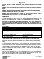
EPA Certied Emissions 1.8 grams per hour
LHV Tested Efciency 1 77.1%
HHV Tested Efciency 2 71.3%
EPA BTU Output 3 12,518 to 38,177 btu/hr
Maximum Wood Length 18 inches
Ideal Wood Length 17 inches
Fuel Seasoned Cord wood
1 Weighted Average Lower Heating Value (LHV) efciency as
tested using CSA B415 Performance testing of solid-fuel-
burning heating appliances. LHV assumes the moisture is
already in a vapour state so there is no loss of energy
2 Weighted Average Higher Heating Value (HHV) efciency
as tested using CSA B415 Performance testing of solid-fuel-
burning heating appliances. HHV includes the energy required
to vaporize the water in the fuel
3 The range of BTU outputs is based on efciency using CSA
B415 Performance testing of solid-fuel-burning heating appli-
ances and burn rates from the low and high EPA tests using
Douglas Fir dimensional lumber.
Efficiency and BTU Output
This heater meets the U.S. Environmental Protection
Agency's 2020 crib wood emission limits for wood
heaters sold after May 15, 2020 using Method 28R.
Under specic test conditions this heater has been
shown to deliver heat at rates ranging from 12,518 to
38,177 Btu/hr.
Emissions testing was performed by PFS-TECO Inc.
SAMPLE
ALT5-LE 140623-28 3100000353

Instruct all members of your family on the safe operation of the heater. Ensure they have enough
knowledge of the entire system if they are expected to operate it. Stress the section on chimney fires
and the importance of following the steps outlined "In Case of Chimney Fire".
Chimney Smoke and Creosote Formation
When wood is burned slowly, it produces tar and other organic vapours, which combine with expelled
moisture to form creosote. The creosote vapours condense in the relatively cool chimney ue of a slow
burning re. As a result, creosote residue accumulates on the ue lining. When ignited, this creosote makes
an extremely hot re. The chimney connector and chimney should be inspected periodically (at least once
every two months) during the heating season to determine if a creosote buildup has occurred. If creosote has
accumulated (3 mm. or more), it should be removed to reduce the risk of a chimney re.
1. Highest smoke densities and emissions occur when a large amount of wood is added to a bed of hot
coals and the air inlet is closed. The heated wood generates smoke, but without ample air, the smoke
cannot burn. Smoke-free, clean burning requires small fuel loads, two or three logs at a time or 1/4 to 1/2
of fuel load and leaving the air inlet relatively wide open, especially during the rst 10 to 30 minutes after
each loading, when most of the smoke generating reactions are occurring. After 30 minutes or so, the air
inlet can be turned down substantially without excessive smoke generation. Wood coals create very little
creosote-producing smoke.
2. The cooler the surface over which the wood smoke is passing, the more creosote will be condensed.
Wet or green wood contributes signicantly to creosote formation as the excess moisture that is boiled
off cools the re, making it difcult for the tars and gases to ignite, thus creating dense smoke and poor
combustion. This moisture-laden smoke cools the chimney, compounding the problem by offering the
smoke the ideal place to condense.
In summary, a certain amount of creosote is inevitable. Regular inspection and cleaning is the solution. The
use of dry, seasoned wood and ample combustion air will help to minimize annoying smoke emissions and
creosote buildup.
Chimney Fires
The dangerous side effect of excessive creosote buildup is a chimney re. This causes much higher than
normal temperatures in the chimney and on its exterior surfaces. Temperatures inside the chimney can
exceed 2000°F (1100°C). Ignition of nearby or touching combustible material is more likely during a chimney
re. Proper clearances are critical to prevent damage during such a re.
Safety
CAUTION: Never use gasoline,
gasoline type lantern fuel, kerosene,
charcoal lighter fluid or similar
liquids to start or "freshen up" a fire
in this heater. Keep all such liquids
well away from the heater while it is
in use.
WARNING: this product can expose you to
chemicals including ceramic bers, which are known
to the state of California to cause cancer,and to carbon
monoxide, which is known to the state of California to
cause birth defects or other reproductive harm.
For more information go to www.p65warnings.ca.gov.
This warning is applicable to all
PACIFIC ENERGY FIREPLACE PRODUCTS
ALT 5-LE 140623-28
4
100000353

Chimney res are easy to detect; they usually involve one or more of the following:
• Flames and sparks shooting out of the top of the chimney
• A roaring sound
• Vibration of the chimney
To Avoid a Chimney Fire
1. Burn wood cleanly. Do not burn wet wood or turn down the unit too quickly after loading.
2. Do not let creosote build up to a point where a chimney re is possible.
3. Do not have res in the heater that may ignite chimney res. These are excessively hot res, such as when
burning household trash, cardboard, Christmas tree limbs, or even ordinary fuel wood; (eg. with a full load
on a hot bed of coals and with the air inlet wide open for more time than is needed to completely char a
fresh fuel load.)
4. The Chimney and connector pipe should be inspected /cleaned periodically.
In the event of a Chimney Fire
1. Prepare to evacuate to ensure everyone's safety. Have a well understood plan of action for evacuation.
Have a place outside where everyone is to meet.
2. Close air inlet on stove.
3. Call local re department. Have a re extinguisher handy. Contact your local municipal or provincial re
authority for further information on how to handle a chimney re. It is most important that you have a
clearly understood plan on how to handle a chimney re.
4. After the chimney re is out, the chimney must be cleaned and checked for stress and cracks before
starting another re. Also check combustibles around the chimney and the roof.
We strongly recommend that your chimney be inspected by professionals who are certified by one of
the following;
NFI (National Fireplace Institute®) in the United States,
CSIA (Chimney Safety Institute of America) in the United States and Canada,
WETT (Wood Energy Technology Transfer) in Canada or
APC (Association des Professionnels du Chauffage) in Quebec
Curing of the Paint Finish
To achieve the best nish, the paint on your stove must be baked on. When burning your stove for the rst
2-3 times it is very important that the room be well ventilated. Open all windows and doors. Smoke and fumes
caused by the curing process may cause discomfort to some individuals.
• Slowly bring the stove to a medium burn, for about 45 minutes. Then increase the to a high burn for an addi-
tional 45-60 minutes
WARNING: Never use chemicals or any other volatile liquid to start a fire. Do not burn garbage, or
flammable fluids such as gasoline, naptha, or engine oil.
ALT5-LE 140623-28 5100000353

CAUTION: Hot while in operation. Keep children, clothing and furniture away. Contact may cause skin
burns.
WARNING: Always keep loading door closed when burning. This heater is not designed for open door
burning.
WARNING: No alteration or modification of the combustion air control assembly is permitted. Any
tampering will void warranty and could be very hazardous.
WARNING: Do not use grates or andirons to elevate the fuel. Burn directly on the fire bricks. Replace
broken or missing bricks. Failure to do so may create a hazardous condition.
Wood Selection
This heater is designed to burn natural wood only. Higher efciency and lower emissions generally result when
burning air-dried seasoned hardwoods, as compared to softwoods or to green or freshly cut hardwoods.
Wood should be properly air dried (seasoned) for six months or more. Wet or undried wood will cause
the fire to smoulder and produce large amounts of smoke and creosote. Wet wood also produces very
little heat and tends to go out often. Wood should be stored under cover away from open flame or heat
sources.
DO NOT BURN :
• Salt water wood * • Treated wood
• Wet or green wood • Coal/charcoal
• Garbage* • Solvents
• Lawn clippings/yard waste • Unseasoned wood
• Railroad ties • Manure or animal remains
• Materials containing rubber, including tires • Materials containing plastic
• Construction or demolition debris • Materials containing asbestos
• Waste petroleum products, paints, paint thin-
ners, or asphalt products
• Paper products, cardboard, plywood, or
particleboard.
* These materials contain chlorides which will rapidly destroy metal surfaces and void warranty.
Burning these materials may result in the release of toxic fumes or render the heater ineffective and cause
smoke.
Do not burn anything but wood. Other fuels, eg. charcoal, can produce large amounts of carbon monoxide, a
tasteless, odorless gas that can kill. Under no circumstances should you attempt to barbecue in this heater.
The prohibition against burning these materials does not prohibit the use of re starters made from paper,
cardboard, saw dust, wax and similar substances for the purpose of starting a re in an affected wood heater.
How to Test Your Wood
Add a large piece of wood to the stove when it has a good large bed of coals. It is dry if it is burning on more
than one side within one minute. It is damp if it turns black and lights within three minutes. If it sizzles, hisses
and blackens without igniting in ve minutes it is soaked and should not be burnt
Operation
ALT 5-LE 140623-28
6
100000353

Lighting a re
WARNING: Never use chemicals or any other volatile liquid to start a fire.
1. Adjust the air control to the “High” position (all the way to the left) and open the door.
2. Place crumpled newspaper in the centre of the heater and crisscross with several pieces of dry kindling.
Add a few small pieces of dry wood on top.
3. Ignite the paper and leave the door ajar approximately 1/2"(13mm) - 1"(25mm) until the wood kindling is
fully engulfed in ame. **Do Not leave stove unattended while the door is open**
4. After the kindling is fully engulfed add a few small logs. Close door.
5. Begin normal operation after a good coal base exists and wood has charred.
Normal Operation
WARNING: This wood heater has a manufacturer-set minimum low burn rate that must not be altered.
It is against federal regulations to alter this setting or otherwise operate this wood heater in a manner
inconsistent with the operating instructions in this manual.
1. Set air control to a desired setting. If smoke pours down across the glass (waterfall effect) this indicates
you have shut the control down too soon or you are using too low a setting. The wide range of control
makes nding the desired setting for your application easy. As every home's heating needs vary (ie.
insulation, windows, climate, etc.) the proper setting can only be found by trial and error and should be
noted for future burns.
2. To refuel, adjust air control to high, and give the re time to brighten. Open the door slowly, this will
prevent back pufng.
3. Use wood of different shape, diameter and length (up to 18"(457mm)). Load your wood endwise and try
to place the logs so that the air can ow between them. Always use dry wood.
4. Do not load fuel to a height or in such a manner that would be hazardous when opening the door.
5. For extended or overnight burns, unsplit logs are preferred. Remember to char the wood completely on
maximum setting before adjusting air control for overnight burn.
• Burn wood only, dry and well seasoned. The denser or heavier the wood when dry, the greater its heat
value. This is why hardwoods are generally preferred. Green or wet wood will cause a rapid buildup of
creosote. If you feel it is necessary to burn wet or unseasoned wood, do so only with the air inlet set
open enough to maintain a good strong re and fairly high chimney temperatures. Do not attempt to burn
overnight using green wood or wet wood. Wet wood can cause up to 25% drop in heater output, as well
as contributing signicantly to creosote buildup.
DO NOT OVER FIRE THIS HEATER: Attempts to achieve heat output rates that exceed heater design
specifications can result in permanent damage to the heater and chimney. A glowing red, top or vent
pipe are indications of over ring. Failure to rectify an over ring condition can be hazardous and may void
the manufacturer's warranty.
ALT5-LE 140623-28 7100000353

Restarting After Extended or Overnight Burns
1. Open door and rake hot embers towards the front of the heater. Add a couple of dry, split logs on top of
embers, close door.
2. Adjust air control to high and in just a few minutes, logs should begin burning.
3. After wood has charred, reset air control to desired setting.
4. To achieve maximum ring rate, set control to high "H". Do not use this setting other than for starting or
preheating fresh fuel loads.
Proper Draft
1. Draft is the force which moves air from the appliance up through the chimney. The amount of draft in your
chimney depends on the length of the chimney, local geography, nearby obstructions and other factors.
2. Too much draft may cause excessive temperatures in the appliance. An uncontrollable burn or a glowing
red stove part or chimney indicates excessive draft.
3. Inadequate draft may cause back pufng into the room and plugging of the chimney. Smoke leaking into
the room through appliance and chimney connector joints indicates inadequate draft.
Remember the "correct" air control setting is affected by variables such as type of wood, outside tempera-
ture, chimney size and weather conditions.
Ash Removal
Caution: Ashes are to be removed only when the heater is cold. Whenever ashes get 3"(76mm) to 4"(102mm)
deep in your rebox, and when re has burned down and cooled, remove excess ashes. Leave an ash bed
approximately 1" (25 mm) deep on the rebox bottom to help maintain a hot charcoal bed.
Ash Clean out system:
The ash dump handle is located under the ash lip on the left hand side. To operate ash dump, pull handle out
1/2"(13mm) and turn clockwise. This will unlock the ash dump and allow it to open. Hold handle open while
pulling ashes into the opening. Avoid large embers as these still contain heat value. Release handle and push
in to lock. Ensure ash dump door is properly engaged. Fill the cavity with the remaining ash level with the
rebox oor. Lift and pull out ash pan and discard ashes into metal container. Replace ash pan and ensure it
is seated properly.
Do not burn with ash dump door open. Doing so will create a hazardous condition. Always leave about
1"(25mm) of ash when cleaning.
Disposal of Ashes
Ashes should be placed in a metal container with a tight tting lid. The closed container of ashes should
be placed on a non-combustible oor or on the ground, well away from all combustible materials, pending
nal disposal. If the ashes are disposed of by burial in soil or otherwise locally dispersed, they should be
retained in closed container until all cinders have thoroughly cooled. Other waste should not be placed in this
container.
ALT 5-LE 140623-28
8
100000353

1. If glass becomes darkened through slow burning or poor wood, it can readily be cleaned with replace
glass cleaner when stove is cold. Never scrape with an object that might scratch the glass. The type and
amount of deposit on the glass is a good indication of the ue pipe and chimney buildup. A light brown
dusty deposit that is easily wiped off usually indicates good combustion and dry, well-seasoned wood and
therefore relatively clean pipes and chimney. On the other hand, a black greasy deposit that is difcult to
remove is a result of wet and green wood and too slow a burning rate. This heavy deposit is building up
at least as quickly in the chimney.
2. DOOR GASKETS - The gasket used by Pacic Energy (5/16"medium density berglass rope) requires only
light pressure to seal. This will prolong seal life. It is important that the door seal be maintained in good
condition. Periodically inspect seals and replace if necessary. Follow the instructions included in the kit,
obtainable from your nearest Pacic Energy dealer.
3. DOOR GLASS - Do not slam loading door or otherwise impact glass. When closing door, make sure that
no logs protrude to impact the glass. If the glass gets cracked or broken, it must be replaced before using
the stove. Replacement glass can be obtained from your dealer. Use 17-1/4"(438mm) x 11-3/8"(289mm)
x 5 mm. Ceramic glass only. Do not substitute with any other type.
• To remove broken glass, undo the four retaining screws and remove clamps and frame, noting position for
re-assembly. Remove all particles of glass . Be careful as they are very sharp. Install new glass complete
with gasket. Replace frame, clamps and screws.
CAUTION:
- do not overtighten, tighten screws very carefully
- do not clean glass when hot
- do not use abrasive cleaners on glass
4. The area where boost combustion air enters the rebox must be kept clear of excessive ash buildup
which will block air ow. This area is at the front of the rebox.
5. Do not store wood within heater installation clearances, or within the space required for fuel loading
and ash removal. Keep the area around the heater clean and free of loose combustibles, furniture,
newspapers, etc.
6. If the plated door requires cleaning, use mild soap and water only. Use of abrasive cleaners will void
warranty.
7. Establish a routine for the fuel, wood burning and ring technique. Check daily for creosote buildup until
experience shows how often you need to clean to be safe.
8. Be aware that the hotter the re, the less creosote is deposited. Weekly cleaning may be necessary in
mild weather, even though monthly cleaning is usually enough in the coldest months when burning rates
are higher. When wood is burned slowly, it produces tar and other organic vapours, which combine with
expelled
Maintenance
WARNING: Never use chemicals or any other volatile liquid to start a fire. Do not burn garbage, or
flammable fluids such as gasoline, naptha, or engine oil.
WARNING: ONLY USE MATERIALS SUPPLIED BY MANUFACTURER WHEN DOING MAINTENANCE OR
REPLACEMENTS.
ALT5-LE 140623-28 9100000353

Chimney connector pipe should be disconnected from stove to clean and inspect. Only if this is not possible
should you remove bafe assembly.
DO NOT OPERATE WITH BAFFLE ASSEMBLY OR INSULATION REMOVED.
Removal:
Remove retaining pin at the back top of the rebox, just under the bafe. Lift bafe up and pull forward to
disconnect from the supply tube. Tilt bafe sideways to drop down and remove from rebox. Inspect gas-
ket between bafe and supply tube. If necessary, replace with part # 80000365, available from your Pacic
Energy dealer. Re-install bafe assembly in reverse order. The two side pieces of insulation must be tight
against the side rails.
Baffle Removal
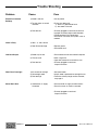
Check the following parts for damage such as cracks, excessive corrosion, burned out sections and
excessive warping: (See website for descriptions and more detail)
Weekly:
• Firebrick - Visual, for cracking.
• Door Gasket - sagging, placement, damage.
Monthly
• Brick rail tabs and brick rails.
• Air riser tube in the back of the rebox.
• Back side of airwash chamber.
• Bafe locking pin.
• Boost tube cover.
When Cleaning the Chimney System:
• Top bafe board/blanket.
• Bafe.
• Top heat shield and mounting bolt.
• Bafe Gasket.
• Brick Rails.
• Manifold.
Blower:
• The blower should be cleaned out a minimum every six months by using a vacuum on the grill openings in
the back and bottom of the blower casing to remove any dust and debris.
Baffle:
• Some warping of the bafe is normal (up to 1/4” or .65cm). Replace if the bafe has permanent warping
greater than this or has cracking or breakage.
• Please contact your Dealer if you experience any of the damage listed above. Continuing to operate your
stove with broken parts may accelerate damage to other parts and may void your warranty
Maintenance Checks
ALT 5-LE 140623-28
10
100000353

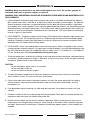
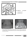
1. Carefully remove wood crating top and supports.
2. Remove plastic cover.
3. Remove the Brick Pack from the rebox. Install Firebricks (see section; Firebrick Installeation) after stove
is in its nal location, and the chimney is installed.
Assembly
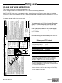
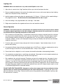
Dimensions
10 1/8”
257mm
25”
635mm
29 3/4”
756mm
28 3/4”
730mm 28 1/2”
724mm
Figure 1: T5 LE Dimensions.
ALT5-LE 140623-28 11 100000353

In Canada: 18" (457 mm) on
the ring side and 8" (203 mm)
to the other sides.
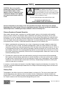
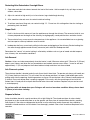
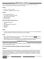
Floor Protector
The stove may be installed on a combustible oor provided noncombustible ember protection is used.
This protection must extend as follows:
In USA: 16" (406 mm) to the front and 8"
(203 mm) to the sides of the fuel loading
door opening. See Figure #4, below.
This protection is also required under
the chimney connector and 2" (51 mm)
beyond each side if using any horizontal
venting.
16" [406mm]
8"
203mm
8"
203mm
U.S.A. Only
Minimum Width - 34"(864mm)
Minimum Overall Depth - 40 1/2"(1.03m)
Non-combustible
floor protector
4"
101mm
Canada Only
8" [203mm]
18" [457mm]
8" [203mm]
8" [203mm]
Minimum Width - 40'(1.02m)
Minimum Overall Depth - 50 1/2"(1.28m)
Non-combustible
floor protector
Figure 2: T5 Floor protector - USA
Figure 3: T5 Floor protector - Canada.
ALT 5-LE 140623-28
12
100000353

Residential Installation
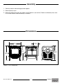
Clearances:
Clearances may be reduced with various heat shielding/insulating materials. Consult CSA B365 or NFPA 211
and local re codes and authorities for approval. For close clearances, use a listed double-wall connector.
NOTE: local/national codes or regulations may override some guidelines in this manual
We recommend that our products be installed and /or serviced by professionals who are certified by
one of the following;
NFI (National Fireplace Institute®) in the United States,
CSIA (Chimney Safety Institute of America) in the United States and Canada,
WETT (Wood Energy Technology Transfer) in Canada or
APC (Association des Professionnels du Chauffage) in Quebec
18"
457mm
8"
203mm
14"
356mm
26"
660mm
21"
533mm
7"
178mm
7"
178mm
18"
457mm
4"
102mm
4"
102mm
14"
356mm
14"
356mm
26"
6601mm
5"
127mm
15"
381mm
14"
356mm
26"
660mm
Alcove: Min. Height 7'(2.13m)
Max. Depth 3'(914 m m)
5"
127mm
15"
381mm
Single Wall Connector - Residential
Double Wall Connector - Residential
Figure 4: T5 Minimum clearances.
ALT5-LE 140623-28 13 100000353

Warning: Under no circumstances is this heater to be installed in a makeshift or "temporary" manner. It
may be fired only after the following conditions have been met.
DO NOT ATTEMPT TO CONNECT THIS HEATER TO ANY AIR DISTRIBUTION DUCT.
DO NOT INSTALL IN ANY FIREPLACE.
Outside combustion air or fresh air into the room may be required in your area, consult local building
codes (see Combustion Air section).
Chimney and Connector
• The chimney system must be a ULC-S629 or UL-103HT listed Stainless chimney or a Masonry chimney
suitable for use with solid fuel, that is lined, in good condition and meets re and building codes.
• The chimney ue size should be the same as the stove outlet (6 inches) for optimal performance.
Reducing or increasing the ue size may adversely affect stove performance.
• Chimney ue exit is to be 3 feet (1 m.) above roof and two feet (0.6 m) above highest projection within 10
feet (3 m).
• The installation must meet all local codes.
• Do not connect this unit to a chimney ue serving another appliance. Minimum system height is 15 feet
(4.6 m.) (measured from base of appliance).
BOTH CHIMNEY SYSTEM AND CONNECTOR MUST BE LISTED TO:
IN CANADA - ULC S-641 LISTED double wall connector and ULC-S629 LISTED CHIMNEY,
IN USA - UL-103 HT LISTED CONNECTOR AND CHIMNEY
When using a Double-Wall Connector
• Use a listed double-wall connector.
• If a listed chimney and double-wall connector are to be connected to the stove, install all components as
per the chimney/connector manufacturer's installation requirements.
When using a Single-Wall (smoke pipe) Connector
The single wall pipe section must be:
• If you are using smoke pipe/chimney connector in conjunction with the listed chimney system, consult
local/national re or building codes for connector installation. Follow the chimney manufacturer's
complete instructions for the installation of the chimney system.
• As short and straight as possible, use six inch diameter, 24 gauge black pipe that is clean and in new
condition.
• Installed with the crimped or male ends pointing down. (This will carry any liquid creosote or condensation
back into the stove) and secured at every joint and collar with 3 sheet metal screws.
• The chimney connector shall not pass through an attic, roof space, closet or similar concealed space,
oor, or ceiling. Where passage through a wall, or partition of combustible material is desired, the installa-
tion shall conform to CAN/CSA-B365, Installation Code for Solid-Fuel-Burning Appliances and Equipment
ALT 5-LE 140623-28
14
100000353

Installation Procedure
1. Select the position for your wood stove based on the clearances diagram. Position the stove and oor
protection.
2. Mark the position for the hole in the ceiling and roof by using a string and plumb-bob hanging over the
exact center of the stoves ue pipe.
3. Check that the intended location will not interfere with oor joists, ceiling joists or rafters before proceed-
ing further. Adjust if necessary and reconrm the clearance's from the stove to combustibles.
4. Carefully follow the directions of the listed chimney for installation of the chimney system from the ceiling
through to the rain cap. This may include framing in holes etc.
5. Start installing smoke pipe (chimney connector), slip crimped edge of the pipe inside the stove collar. Use
holes provided in collar to secure pipe with two screws.
6. Install the remaining lengths of pipe one on top of the other up to the nished height of the chimney and
using the manufacturers approved adapter, secure to each other. A slip section can make this easier.
Combustion Air
Intake or combustion air can be supplied to the stove in one of two ways. Consult your local building code or
CAN/CSA-B365, Installation Code for Solid-Fuel-Burning Appliances and Equipment before proceeding.
1. Outside air supply - (Necessary for mobile home installation, optional for residential installation). Outside
air may be drawn from either underneath the stove or from behind.
• To draw outside air through the floor - This hole must get its air from a ventilated crawl space or be
extended with duct to the outdoors (see Figure #5,6, Page 16-17). The use of outside combustion air for
residential installation requires the unit to be secured to the structure to prevent dislodging of the air duct.
• Cut or drill a hole in the oor, (large enough to t 4" metal venting) behind the ash box enclosure. Install
metal venting thru the hole and under the oor as required by building code. Once the stove is in place,
attach the 4" OAIR adapter to the Ash Box Enclosure. Connect the adapter to the metal with 4"(100mm)
i.d. exible metal ducting.
• To draw outside air from behind the stove, Use a 4"(100mm) Wall Air Intake. Following the Air Intake
Kit's instructions Cut or drill the recommended size hole through the wall behind the unit. Install the 4"
Intake Adapter over the hole in the rear of the Ash Box enclosure. Attach exible metal ducting between
the intake adapter and the Air Intake kit.
2. Room air supply - The stove will draw its air from the room through the opening in the Ash Box Enclosure
and into the rebox intake.
Note: The living space around the heater must be well ventilated with good air circulation. Anything that may
cause a negative pressure can cause gases or fumes to be pulled into the living area. During extremely cold
weather, and especially when burning at very slow rates, the upper parts of the exposed chimney may ice up,
partially blocking the ue gases. If blockage occurs, ue gases may enter living space.
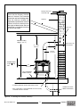
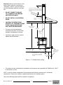
ALT5-LE 140623-28 15 100000353

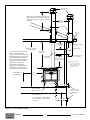
Spark arrester
rain cap
Listed
Insulated
Chimney
Storm collar
Roof
ashing
Chimney Support
Wall Thimble
Alternate up and
out installation
Non-combustible
Ember Protector 4" diameter hooded
air inlet or 90 elbow
turned down with
rodent screen.
as per Local
and Federal
codes
12” [300mm]
Minimum rst
section of pipe
Chimney
connector
Minimum 7’ [2.1m]
Ceiling Height
48”
[1.2 m]
Unit may be harder
to start. Please provide
as much vertical length
for the rst section
of pipe as possible
Follow chimney manufacture specifcations for
distance between vent termination heigth and
chimney at roof line. Also consult local building
regulations.
*
*
The chimney may incorporate an
offset. To do this safely, all
sections of listed connector, offset
elbows and chimney section must
be screwed together by at least
three sheet metal screws per joint.
The chimney must be suitably
supported by the chimney
manufacturer's listed offset
support. All vent manufacturer or
national re code clearances to
combustible must be observed.
55“ [1.4m]
Minimum
Combustibles in
front of the unit
* 4” (102 mm) diameter air inlet
with rodent screen.
* If the crawl space is well ventilated
it is not necessary to extend air inlet
to outside.
Figure 5: T5 residential venting.
ALT 5-LE 140623-28
16
100000353

Fireclay Flue Liner
Concrete Cap
Chimney
Approved Through
Wall Installation
55” (1.4m)
Minimum
Minimum Ceiling
Height 7’ (2.1 m)
48”
(1219 mm)
Non-combustible
Ember Protector
Hooded vent or 90°
elbow turned down.
Chimney
Connector
Ensure that the Masonry chimney
meets all National Fire Protection
Association and local building codes.
Have the chimney cleaned and
inspected by a professional to ensure
there are no cracks, weak mortar or
other signs of deterioration. See vent
manufactuer’s installation instructions
for further information
* 4"(102mm) diameter air inlet with rodent screen
* If the crawl space is well ventilated it is not necessary
to extend air inlet to outside
Combustibles
in front of the
unit
6” S.S. liner
Figure 6: T5 Venting to a masonry chimney.
ALT5-LE 140623-28 17 100000353

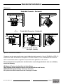
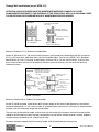
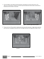
Through Wall Installations (as per NFPA 211)
ATTENTION: VAPOUR BARRIER MUST BE MAINTAINED WHEREVER CHIMNEY OR OTHER
COMPONENTS PENETRATE TO THE EXTERIOR OF THE STRUCTURE. SEE LOCAL BUILDING CODES
FOR PROPER AND APPROVED METHODS OF MAINTAINING VAPOUR BARRIER.
Minimum Clearance 12 in. (305mm) to combustibles
System A. Minimum 3.5 in. (90 mm) thick brick masonry wall framed into combustible wall with a minimum
of 12 in. (305 mm) brick separation from clay liner to combustibles. Fireclay liner (ASTM C 315, Standard
Specications for Clay Fire Linings, or equivalent), minimum 5/8 in. (16 mm) wall thickness, shall run from
outer surface of brick wall to, but not beyond, the inner surface of chimney ue liner and shall be rmly
cemented in place.
Minimum Clearance 9 in. (229mm) to combustibles
System B. Solid-Insulated, listed factory-built chimney length of the same inside diameter as the chimney
connector and having 1 in. (25.4 mm) or more of insulation with a minimum 9 in. (229 mm) air space between
the outer wall of the chimney length and combustibles.
The inner end of the chimney length shall be ush with the inside of the masonry chimney ue and shall be
sealed to the ue and to the brick masonry penetration with non-water-soluble refractory cement. Supports
shall be securely fastened to wall surfaces on all sides.
Fasteners between supports and the chimney length shall not penetrate the chimney liner.
SYSTEM A
Minimum 12” (305 mm)
to combustibles
Minimum chimney clearance
to brick and combustibles
2” (51 mm).
Minimum clearance
12” (305 mm) of brick
Chimney connector
Fireclay liner
Masonry chimney
constructed to NFPA 211
Chimney ue
SYSTEM B Minimum chimney clearance
from masonry to sheet steel
supports and combustibles
2” (51 mm)
Factory built
chimney length
Solid-insulated, listed
factory built chimney
length
Chimney length
ush with inside
of ue
Air space:
9” (229 mm) min.
Sheet steel supports
Masonry chimney
constructed to NFPA 211
Chimney
ue
Minimum clearance
9” (229 mm)
Use chimney
manufacturers’ parts to
attach connector
securely
Chimney connector
Nonsoluble
refractory
cement
Figure 7: System A
Figure 8: System B.
ALT 5-LE 140623-28
18
100000353

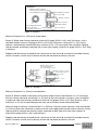
Minimum Clearance: 2 in. (51mm) to combustibles
System D. Solid-Insulated, listed factory-built chimney length with an inside diameter 2 in. (51 mm) larger
than the chimney connector and having 1 in. (25.4mm) or more of insulation, serving as a pass-through for
a single-wall sheet steel chimney connector of minimum 24 gauge [0.024 in. (0.61 mm)] thickness, with a
minimum 2 in. (51 mm) air space between the outer wall of chimney section and combustibles.
Minimum length of chimney section shall be 12 in. (305 mm). Chimney section concentric with and spaced 1
in. (25.4 mm) away from connector by means of sheet steel support plates on both ends of chimney section.
Opening shall be covered, and chimney section supported on both sides with sheet steel supports of
minimum 24 gauge [0.024 in. (0.61 mm)] thickness.
Supports shall be securely fastened to wall surfaces on all sides and shall be sized to t and hold chimney
section. Fasteners used to secure chimney section shall not penetrate chimney ue liner.
Minimum Clearance: 6 in. (152mm) to combustibles
System C. Sheet steel chimney connector, minimum 24 gauge [0.024 in. (0.61 mm)] in thickness, with a
ventilated thimble, minimum 24 gauge [0.024 in. (0.61 mm)] in thickness, having two 1 in. (25.4 mm) air
channels, separated from combustibles by a minimum of 6 in. (152 mm) of glass ber insulation. Opening
shall be covered, and thimble supported with a sheet steel support, minimum 24 gauge [0.024 in. (0.61 mm))]
in thickness.
Supports shall be securely fastened to wall surfaces on all sides and shall be sized to t and hold chimney
section. Fasteners used to secure chimney section shall not penetrate chimney ue liner.
SYSTEM C
Minimum 6” (152 mm)
glass ber insulation
Two ventilated air channels,
each 1” (25.4 mm);
construction of sheet steel
Chimney connector
Masonry chimney
constructed to NFPA 211
Chimney ue
Minimum chimney clearance
from masonry to sheet steel supports
and combustibles 2” (51 mm)
Sheet steel supports
Two ventilated air channels,
each 1” (25.4 mm)
SYSTEM D
Sheet steel
supports
Chimney
section
Chimney
connector
Air space:
2” (51 mm) min.
Chimney ue
Minimum chimney clearance
to sheet steel supports
and combustibles 2” (51 mm)
Minimum clearance 2” (51 mm)
1” (25.4 mm) air space to
chimney length
Masonry chimney
constructed to NFPA 211
Sheet steel supports
Chimney connector
Chimney length
Figure 9: System C
Figure 10: System D
ALT5-LE 140623-28 19 100000353

The optional blower kit (kit #WODC.BLOWB) is equipped with a three prong power cord and may be installed
at any time. Follow installation instructions supplied with the kit. Route power supply cord away from heater.
Electrical rating: 115 volts A.C.-1.1 amps.
Fan output rating: 140 CFM
Blower Operation
Proper blower speed matched with air control setting will ensure peak performance from your stove. Operate
as follows:
• Air control set to "L" (low), operate blower speed control on "Low".
• Air control set between "L" and "H" (low and high), operate blower speed control at desired setting.
Automatic: To operate the blower automatically, set the rocker switch on the side of the fan housing to
"Auto" and set the speed control to desired setting. This will allow the fan to turn on as the stove heats up to
operating temperature. It will also shut the blower off after the re has gone out and the unit cooled to below a
useful heat output range.
Manual: To manually operate the blower, set the rocker switch to "Man" and set the speed control to desired
setting. This will bypass the sensing device and allow full control of the blower. Switching from "Auto" to
"Man" or selecting speed may be done anytime.
Optional Blower
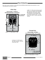
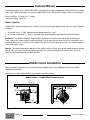
Mobile Home Installation
14"
356mm
15"
381mm
18"
457mm
26"
660mm
5"
127mm
4"
102mm
4"
102mm
Mobile Home - Double Wall Connector only
Figure 11: T5 Minimum clearances - Mobile Home.
These mandatory requirements for installation into a mobile Home, are in addition to those listed under
Residential Installation.
Clearances to combustible surfaces and materials are shown below.
ALT 5-LE 140623-28
20
100000353
La page charge ...
La page charge ...
La page charge ...
La page charge ...
La page charge ...
La page charge ...
La page charge ...
La page charge ...
-
 1
1
-
 2
2
-
 3
3
-
 4
4
-
 5
5
-
 6
6
-
 7
7
-
 8
8
-
 9
9
-
 10
10
-
 11
11
-
 12
12
-
 13
13
-
 14
14
-
 15
15
-
 16
16
-
 17
17
-
 18
18
-
 19
19
-
 20
20
-
 21
21
-
 22
22
-
 23
23
-
 24
24
-
 25
25
-
 26
26
-
 27
27
-
 28
28


Pacific energy ALDERLEA T5 LE Manuel utilisateur
- Catégorie
- Poêles
- Taper
- Manuel utilisateur
- Ce manuel convient également à
Documents connexes
Autres documents
-
 Quadrafire Discovery I Wood Stove Manuel utilisateur
-
 Quadrafire 2100 Millennium Wood Stove Manuel utilisateur
-
Quadrafire Discovery II Wood Stove Le manuel du propriétaire
-
 Quadrafire 3100 Millennium Wood Stove Manuel utilisateur
-
-
United States Stove Company VG1120 Series Le manuel du propriétaire
-
Ashley Hearth Products AW1820E Le manuel du propriétaire
-
United States Stove TR007E Le manuel du propriétaire


