Modern Forms Ultra UV-C Replacement Module Mode d'emploi
- Catégorie
- Ventilateurs ménagers
- Taper
- Mode d'emploi
Ce manuel convient également à

Ultra
Smart Fan
Installation Instructions
works with the
Google Assistant

FR-D2102
Ultra Smart Fan Instructions2
Please read and
save these instructions
before installation
DO NOT RETURN TO STORE

FR-D2102 Ultra Smart Fan Instructions 3
For all questions about your ceiling fan please read all included
instructions, installation procedures, troubleshooting guidelines
and warranty information before starting installation.
For missing parts or general inquiries call our trained technical staff at:
1-866-810-6615 option 1
MON-FRI 8AM-8PM EST
Email: customerservice@modernforms.com
Or live chat at modernforms.com
For fast service have the following information below when you call:
1. Model Name and Number
2. Part Number and Part Description
3. Date Of Purchase and Purchase Location
1-866-810-6615 option 2
MON-FRI 8AM-8PM EST
Email: fansupport@modernforms.com
General Inquiries
Fan Support

FR-D2102
Ultra Smart Fan Instructions4
For operation, maintenance, and troubleshooting information,
visit http://modernforms.com/fan-support/
To reduce the risk of electric shock, ensure electricity has been turned off at the circuit breaker
before beginning. All wiring must be in accordance with the National Electrical Code “ANSI/NFPA
70” and local electrical codes. Electrical installation should be performed by a licensed electrician.
The fan must be mounted with a minimum of 7 ft. (2.1m) clearance from the trailing edge of
the fan blades to the floor and a minimum of 1.5 ft (0.5m) from the edge of the fan blades to the
surrounding walls. Never place objects in the path of the fan blades. To avoid personal injury or
damage to the fan and other items, please be cautious when working around or cleaning the fan.
To avoid electrical shock or damage to the motor or finish, do not use water or chemicals
when cleaning the fan or fan blades. A dry cloth or lightly dampened cloth will be suitable
for most cleaning.
After making electrical connections, spliced conductors should be turned upward and pushed
carefully up into the outlet box. The wires should be spread apart with the grounded conductor and
the equipment-grounding conductor on one side of the outlet box, and the ungrounded conductor
on the other side of the outlet box.
WARNING: This product should be installed by a licensed electrician. This product should be
mounted to an outlet box UL-listed marked “Acceptable for fan support” of 15.9 kg (35 lbs) or
less and should use mounting screws provided with the outlet box and/or support directly from
building structure. Most outlet boxes commonly used for the support of luminaires are not
acceptable for fan support. Consult a licensed electrician.
All set screws must be checked and re-tightened
where necessary before installation.
WARNING: Do not install or use your fan if any part(s) is/are damaged or missing. This product
is designed for use only with the supplied parts and/or accessories designated for use with this
product by Modern Forms. Substitution of parts or accessories not designated for use with this
product by Modern Forms could result in personal injury or property damage and will void the
warranty. Contact an authorized dealer or the manufacturer if any parts are damaged or missing.
WARNING: Do not install this product in a location or manner that is not specifically designed
to accomodate the product as set forth in the instructin manual. Failure to use the product as
instructed may cause serious injury or damage.
WARNING: To reduce the risk of electric shock, this fan must be installed and operated with the
supplied remote control, or controlled from the Modern Forms app.
WARNING: Do not use power tools to assemble or install your fan. Using power tools can result in
improper assembly which can lead to noise or fan damage, personal injury or property damage.
WARNING: To reduce the risk of personal injury, do not bend the blade arms when installing the
brackets, balancing the blades or cleaning the fan.
WARNING: Do not insert foreign objects between rotating fan blades.
WARNING: Do not operate fan unless fan blades are in place. Noise and fan damage can occur
WARNING: This appliance is not intended for use by young children without supervision.
WARNING: To reduce the risk of fire, electric shock, personal injury or damage to the fan or other
items, the outlet box and support structure must be securely mounted and capable of reliably
supporting a minimum of 35 Ibs (15.9 kg). Use only UL/cUL listed outlet boxes marked “FOR FAN
SUPPORT.” Use only the screws and washers provided with the outlet box.
CAUTION: Before assembling your fan, refer to the “Making the Electrical Connections“
section. If you feel you do not have enough wiring knowledge or experience, have your fan
installed by a licensed electrician.
NOTE: Before servicing or cleaning the fan, switch power off at the circuit breaker.
Safety Rules

FR-D2102 Ultra Smart Fan Instructions 5
When using electrical equipment, basic safety precautions should always be
followed including the following:
WARNING: Ultraviolet (UV) Radiation Hazard. The lamp in this unit produces UVC radiation. Direct
exposure of skin and eyes to UVC radiation may cause damage similar to sunburn reaction to the
skin and injury to the eyes. Never look directly, even briefly, at the light source of a UVC lamp. Skin
burns and eye injuries from UVC exposure usually resolve within a week with no known long-term
damage. Since the penetration depth of UVC radiation is very low, the risk of skin cancer, cataracts
or permanent vision loss is also thought to be very low. The type of eye injury associated with
exposure to UVC causes severe pain and a feeling of having sand in the eyes. Sometimes people
are unable to use their eyes for one to two days. It can occur after a very short exposure (seconds
to minutes) to UVC radiation. This product, including the UVC lamp and all of the product’s
components, should be used as instructed in this manual and the directions for use and operations,
including, including complying with all adequate safety safeguards, including but not limited to,
those indicated in the mounting instructions. This product must be mounted and installed as
instructed to ensure that the UV-C lamp can be operated in a safe way.
WARNING: This equipment is designed for use with UV radiation sources and must be installed in
compliance with technical directions to prevent risk of personal injury from UV radiation.
WARNING: UV radiation can pose a risk of personal injuries. Direct exposure can result in damage
to eyes and skin. To reduce risk of exposure this equipment must be installed in accordance with
the manufacturer’s installation instructions.
WARNING: UV and optical radiation can be reflected by surrounding surfaces such as ceilings and
walls. Since the reflective properties of surfaces can vary widely, they should be considered as
part of site planning. For example, UV light may lead to a change in the color of paint that has not
been UV stabilized. Fading or discoloration of materials directly exposed to UV radiation should be
considered normal wear. Use normal paints for the surface (e.g., the ceiling) above the fan as they
substantially absorb UV light. Do not paint the surface (e.g., the ceiling) with paint designed to
reflect UV light.
WARNING: It is the responsibility of the installer to ensure that persons will not be directly exposed
to UV or optical radiation during equipment operation. This will require the installer to conduct
an assessment of irradiance or illuminance levels in the surrounding occupied spaces prior to
occupancy.
WARNING: Equipment must be mounted in locations and heights where it will not be readily
subjected to tampering by unauthorized personnel.
WARNING: Maintenance and servicing of this UV product must be performed by authorized
personnel. Service personnel must wear appropriate Personal Protective Equipment (PPE) if the
equipment will be in operation during the maintenance or servicing work. Contact the equipment
manufacturer for PPE recommendations and guidance.
WARNING: The use of accessory equipment not recommended by the manufacturer may cause an
unsafe condition.
WARNING: Do not use this equipment for any purpose other than intended use.
WARNING: Do not install the fan where the top of the UV module can be visible, for example,
beneath a catwalk or breezeway that will permit direct exposure to UV radiation.
UV Safety Rules
Disclaimer: Failure to use the product as instructed may also negatively impact the product’s effectiveness.
Manufacturer and its affiliates do not promise or warrant that the use of this product will protect or prevent any user
from infection and/or contamination. This product is not approved nor intended to be used to disinfect any device,
including medical devices. In addition to and without limitation of any exclusions or limitations of liability of the
manufacturer and its affiliates as set forth in the user manual or any agreement for sale, distribution or otherwise making
available of this product, the manufacturer and its affiliates shall have no responsibility or liability whatsoever for any
claim or damage that may arise from or relate to any use of this product outside of its intended use or contrary to the
installation and operation instructions, as described in the user manual and any other documentation provider to the
user, including mounting instruction.
Disclaimer: While there may be information here or on our website relating to the effectiveness of the UV-C technology
incorporated in the ULTRA in reducing SARS-CoV-2 in the breathable air, Modern Forms makes no claims that its
products can cure, treat or prevent any conditions, including COVID-19. Always consult your healthcare provider with any
health-related questions. The ULTRA is not a substitute for good building air exchange practices or manual cleaning and
disinfection practices.

FR-D2102
Ultra Smart Fan Instructions6
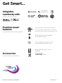
Get Smart...
Integrates
seamlessly with:
devices you already own
works with the
Google Assistant
Premium smart
features:
Accessories:
DC
MOTOR
complement high quality materials
personalize your experience
Quiet, reliable, and up to 70%
more ecient than AC fans
Wi-Fi and Bluetooth enabled
for exible control
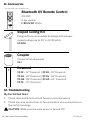
Bluetooth Remote Control
ON/OFF
6 fan speeds
F-RCUV-WT White
Wet Location-listed to the strictest
UL/cUL safety regulations. Finished
and rated for interior and exterior use
ULTRA
VIOLET

FR-D2102 Ultra Smart Fan Instructions 7
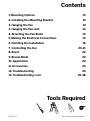
Contents
Tools Required
1. Mounting Options 10
2. Installing the Mounting Bracket 12
3. Hanging the Fan 12
3. Hanging the Fan cont. 14
4. Attaching the Fan Blade 14
5. Making the Electrical Connections 16
6. Finishing the Installation 18
7. Controlling the Fan 20-21
8. Reset 22
9. Breeze Mode 22
10. Application 22
11. Accessories 24
12. Troubleshooting 24
13. Troubleshooting cont. 25-28

FR-D2102
Ultra Smart Fan Instructions8
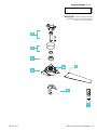
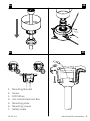
Package Contents
5. Motor Assembly
6. Aluminum Tray
RPL-F-UV7INTRAY-**
(UV Module not included)
UV Module
UVF7IN-120V-R1-MOD
7. Control Receiver
w/Hardware
F-R3-2102-054
8. Remote w/Wall Cradle
F-RCUV-WT
1. Blade Set of 3
RPL-F2102-54-BD-**
2. Hanger Assembly -
Mounting Bracket
Downrod Assembly
RPL-HGR-ASM-10-**
(optional 6” rod included for closer to ceiling
mount applications)
3. Canopy & Canopy
Screw Ring
RPL-CAN-CYL-**
4. Coupling Cover
RPL-COU-CVR-**
** Denotes finish code of fan
Before discarding packaging materials be certain all parts have been removed.
Place the parts from the hardware bag into a small container to keep them from being lost.
• Part A
• Part B
• Part C
• Part D
Hardware Bag
RPL-F2102-PARTS
Hardware Bag
RPL-F2102-PARTS
#10 x 38mm Pan Head Phillip Screws (2)
#10x76mm Pan Head Phillip Wood Screws (1)
(8)
3/16”( 5.2x8.4x1.0mm) Spring Washer (1)
6.5x19x2mm Flat Washer (1)
5.5x12x1mm Flat Washer (10)
3/16” Star Washer (2)
3/16 *6mm Philip Washer Head Screws (10)
5 x 14 x 1mm Flat Washer (2)
B: Blade Screw / Washers
(Found with the receiver)
5A.
5B.
6.
7.
2
1
2
1
If you need a replacement UV module - please order part no. UVF7IN-120V-R1-MOD
If you need a replacement tray - please order part no. RPL-F-UV7INTRAY-**
Contact fansupport@modernforms.com if you need glass fixing plates, silicone rings, or hardware

FR-D2102 Ultra Smart Fan Instructions 9
IMPORTANT: Please make note of
the MAC ID on the receiver and
keep it in a safe place.
MAC ID
7
1
3
6
4
5
5A
2
Hanging Weight: 20 lbs

FR-D2102
Ultra Smart Fan Instructions10
1. Mounting Options
CAUTION: To prevent electrical shock, ensure electricity has been
turned off at the circuit breaker before beginning.
If there isn’t an existing UL/cUL listed outlet box, please refer to the
following instructions. Secure the outlet box directly to the building
structure. Use appropriate fasteners and building materials. The
outlet box and support structure must be able to fully support the
moving weight of the fan (at least 35 lbs/15.9 kg). Do not use plastic
outlet boxes. Use only UL/cUL listed outlet boxes marked
“FOR FAN SUPPORT.”
Secure the outlet box directly to the building structure. Use Part A (if
needed)
Figures 1-1C are examples of different ways to mount the
outlet box.
NOTE: To hang your fan where there is an existing fixture but no
ceiling joist, you may need an installation hanger bar.
NOTE: Downrod fans can be suspended up to a maximum
recommended length of 72” using additional downrods
(sold separately) and the included 80” lead wire.
NOTE: The sloped ceiling kit (sold separately) is required for sloped
ceiling applications, and will accommodate slopes up to 45° (Fig. 1B).
NOTE: You may need a longer downrod to maintain proper blade
clearance when installing on a steep, sloped ceiling (Fig. 1B).

FR-D2102 Ultra Smart Fan Instructions 11
1
1A
1B
1C
1
1
2
1
1
2
3
3
1. Support Brace
2. Outlet Box
3. Joist
1. Support Brace
2. Mounting Bracket
3. Recess Outlet Box
1. Outlet Box
1. Outlet Box
Support Ceiling
Max 30° Angle

FR-D2102
Ultra Smart Fan Instructions12
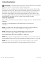
2. Installing the Mounting Bracket
Remember to disconnect the power at the circuit breaker.
1. Remove 1 of 2 screws from the bottom of the mounting bracket
and save for use in section 11. Loosen the other screw (Fig. 2).
2. Pass the 120-volt supply wires through the center hole in the
mounting bracket as shown (Fig. 2A).
3. Secure the mounting bracket to the ceiling outlet box with the
screws and washers provided with your outlet box.
NOTE: Make sure that mounting screws are tight.
1. Take out the screw located in the hanger ball, lower the hanger
ball and remove the cross pin. Remove the hanger ball from the
hanger ball/downrod assembly. (Fig. 4) You may use the optional
6-inch rod if you prefer. The 10-inch rod is optimal for airflow
production and replacing the UV module in the future.
2. Remove the clevis pin and cotter pin and loosen the two collar
screws from the motor collar.
3. Feed motor wires and safety cable through coupling cover,
canopy ring, and canopy. (Fig 4A)
4. Carefully feed the motor wires and safety cable up through the
downrod. Thread the downrod assembly onto motor collar.
(Fig 4B)
4. Hanging the Fan
1. Secure blade with blade attachment screws and washers.
(Fig. 3) Use part B.
2. Repeat this procedure with the remaining blades.
3. You are ready to hang the fan - the UV Tray/Module comes
pre-assembled to the motor housing. Ref. Part No. 5A/5B.
3. Attaching the Fan Blade

FR-D2102 Ultra Smart Fan Instructions 13
2 2A
3 4
1. Mounting Bracket
2. Screw
1
2
2
3
1
To Switch A
A
B
(HOT)
(Neutral)
(HOT)/
Switch
(No Neutral)
(Ground)
*Bare or Green
(Ground)
*Bare or Green
To Switch
1. cUL Listed Electrical Box
2. Mounting Screws
(outlet box screws not included)
3. 120V Wires

FR-D2102
Ultra Smart Fan Instructions14
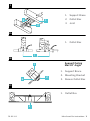
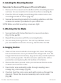
4. Hanging the Fan cont.
5. Align the holes of the downrod and collar and insert the cotter
pin and clevis pin. Tighten the two collar screws. (Fig 4B)
6. Slip the coupling cover, canopy screw ring (painted side down),
and canopy (opened side up) onto the downrod. (Fig. 4B)
7. Reinstall the hanger ball onto the downrod, being sure that the
cross pin is in the correct position and the screw is tightened.
(Fig 4B)
WARNING: Failure to properly install the cotter pin and/or tighten
the set screws could result in the fan loosening and possibly falling.
NOTE: Make sure all screws are tightened and that wires
are not twisted.
8. Carefully lift the fan motor assembly up to the mounting bracket
and seat the hanger ball in the mounting bracket socket. Make
sure the tab on the mounting bracket socket is properly seated
in the groove in the hanger ball. Rotate the socket assembly until
the ball drops and locks into the hanger bracket screw. (Fig. 4C)
9. Secure the safety cable into the structure beams using the wood
screw, washers, and spring washers provided (Fig. 4D).
NOTE: A Safety cable is required for all installations in Canada.
Safety cable is required for ceiling fan and light combinations over
35 lbs. in both flush and downrod models in the United States. Use
Part C.

FR-D2102 Ultra Smart Fan Instructions 15
4A 4B
4D4C
1. Mounting Bracket
2. Screw
3. 120V Wires
4. cUL Listed Electrical Box
5. Mounting plate
6. Mounting screws
7. Safety cable

FR-D2102
Ultra Smart Fan Instructions16
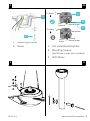
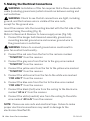
5. Making the Electrical Connections
WARNING: Installation of this fan requires that a three-conductor
cable (including ground wire) which should run between ceiling and
wall outlet box.
WARNING: Check to see that all connections are tight, including
ground, and that no bare wire is visible at the wire nuts,
except for the ground wire.
Insert the receiver into the mounting bracket with the flat side of the
receiver facing the ceiling (Fig. 5).
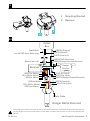
Motor to Receiver & Receiver to house supply wires (Fig. 5A).
1. Connect the hanger ball/downrod assembly ground wire,
mounting bracket ground wire and receiver ground wire to
the ground wire in outlet box
WARNING: Failure to connect ground wires could result in
poor fan control functionality.
2. Connect the red wire from the fan to the red wire marked
“TO MOTOR” from the receiver.
3. Connect the grey wire from the fan to the grey wire marked
“TO MOTOR” from the receiver.
4. Connect the yellow wire from the fan to the yellow wire marked
“TO MOTOR” from the receiver.
5. Connect the white wire from the fan to the white wire marked
“FOR LIGHT” from the receiver.
6. Connect the blue wire from the fan to the blue wire marked
“FOR LIGHT” from the receiver.
7. Connect the black (hot) wire from the ceiling to the black wire
marked “AC in L” from the receiver.
8. Connect the white (neutral) wire from the ceiling to the white
wire marked “AC in N” from the receiver.
NOTE: Please use wire nuts and electrical tape. Failure to make
proper electrical connections may result in damage to the
electronics. Use Part D.

FR-D2102 Ultra Smart Fan Instructions 17
Black(Hot)
can be RED from Switch leg
Black(Line in H)
RED(to Motor)
GREEN(Ground)
BLUE (to Light)
BLUE (for Light)
GREEN(GND Must Use)
GREEN(Hanger Bracket Ground)
GREEN(Hanger Bracket Ground)
RED(to Motor)
GREY(to Motor)
WHITE(Neutral)
WHITE(to Light)
WHITE(Neutral)
Safety Cable
GREY(to Motor)
YELLOW(to Motor)
WHITE(Line in N)
YELLOW(to Motor)
Outlet
Box
Receiver
Hanger Ball & Downrod
Hanger
Bracket
Follow the steps above to connect the fan to your household wiring. Use the plastic wire nuts with your fan.
Secure the plastic wire nuts with electrical tape. Make sure there are no loose strands or connections. Use
Part D.
5
5A
1
2
1. Mounting Bracket
2. Receiver

FR-D2102
Ultra Smart Fan Instructions18
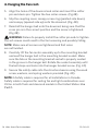
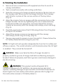
6. Finishing the Installation
1. Secure all wire connections with supplied wire ties to assist in
canopy installation.
2. Tuck connections neatly into ceiling outlet box.
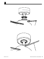
3. Slide the canopy up to hanger bracket and place the key hole on
the canopy over the screw on the hanger bracket. Turn canopy
until it locks in place at the narrow section of the key holes.
(Fig. 6)
4. Align the circular hole on canopy with the remaining hole on the
hanger bracket. Secure by tightening the one screw previously
loosened and the one previously removed. Adjust the canopy
screws as necessary until the canopy and canopy cover are snug.
(Fig. 6)
5. Carefully read and remove the UV Warning sticker from the glass
on top of UV module.
6. Adjust the canopy screws as necessary until the canopy
and canopy screw ring are snug. (Fig. 6)
7. You are now ready to power on your fan and UV. Please follow the
UV Safety Rules before turning on your fan.
WARNING:
This product emits ultraviolet (UV)
radiation. Exposure to UV radiation can cause serious personal
injuries, including damage to eyes and skin. Avoid direct exposure to
the UV light. For more safety instructions, please refer to page 5 of
this instruction manual (“UV Safety Rules”).
NOTE: UV light will not operate independently from fan for safety and
efficacy reasons. The violet indicators will illuminate when the UV light
is enabled. They cannot be turned off.
WARNING: Make sure tab at bottom of hanger bracket is
properly seated in groove of hanger ball before attaching canopy to
bracket. Failure to properly seat tab in groove could cause damage to
electrical wiring.

FR-D2102 Ultra Smart Fan Instructions 19
6

FR-D2102
Ultra Smart Fan Instructions20
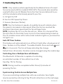
NOTE: Only remote controls specifically for the Modern Forms UV smart
fan can be used with this model (F-RCUV-WT). The remote also cannot be
used with other non-UV Modern Forms Fan Your fan was delivered to you
with the included control already paired to your fan.
A: UV light On/Off
B: Fan On/Off, Speed Up/Down
C: Season (Summer/Winter)
NOTE: Your fan features 6 speeds. An audible tone will indicate when
the speed is increased or decreased. When the fan has reached the
minimum/maximum speed level the fan will beep twice.
NOTE: Anytime the UV is on the fan will run. When UV is turned off the
fan will return to the state it was in prior to the module being turned on.
The UV module comes with 3 ultra-violet indicator lights so you know the
UV light is on.
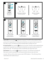
Auto Off Timer Feature
This feature will automatically turn off the UV light after a fixed period of
time. Feature is off by default. To enable/disable, Press and hold and
for 4 seconds. The fan will beep indicating the change.
Default time: 45 minutes. Duration can be changed using the mobile App.
Controlling One or Multiple Fans with Remote
The Bluetooth UV Remote is capable of controlling
an unlimited number of fans within line of site.
See (Fig. 7C) for Pairing.
NOTE: Pairing must be completed within three (3) minutes of
powering the fan.
Synchronizing Control Across Multiple Fans
If you are controlling multiple fans with one controller, fans/lights
may be synced by referring to Fig. 7B and instructions on the next page.
7. Controlling the Fan
La page est en cours de chargement...
La page est en cours de chargement...
La page est en cours de chargement...
La page est en cours de chargement...
La page est en cours de chargement...
La page est en cours de chargement...
La page est en cours de chargement...
La page est en cours de chargement...
La page est en cours de chargement...
La page est en cours de chargement...
La page est en cours de chargement...
La page est en cours de chargement...
-
 1
1
-
 2
2
-
 3
3
-
 4
4
-
 5
5
-
 6
6
-
 7
7
-
 8
8
-
 9
9
-
 10
10
-
 11
11
-
 12
12
-
 13
13
-
 14
14
-
 15
15
-
 16
16
-
 17
17
-
 18
18
-
 19
19
-
 20
20
-
 21
21
-
 22
22
-
 23
23
-
 24
24
-
 25
25
-
 26
26
-
 27
27
-
 28
28
-
 29
29
-
 30
30
-
 31
31
-
 32
32


Modern Forms Ultra UV-C Replacement Module Mode d'emploi
- Catégorie
- Ventilateurs ménagers
- Taper
- Mode d'emploi
- Ce manuel convient également à
dans d''autres langues
Documents connexes
-
Modern Forms FR-W1805-120L-BZ Mode d'emploi
-
Modern Forms FR-W2303 Aura Mode d'emploi
-
-
-
-
-
-
-
-