
OPERATION AND INSTALLATION
OPERACIÓN E INSTALACIÓN
UTILISATION ET INSTALLATION
TANKLESS ELECTRIC WATER HEATERS | CALENTADORES DE AGUA SIN TANQUE | CHAUFFE-EAU
INSTANTANÉS ÉLECTRIQUES
» TEMPRA® 12 B
» TEMPRA® 15 B
» TEMPRA® 20 B
» TEMPRA® 24 B
» TEMPRA® 29 B
» TEMPRA® 36 B
» TEMPRA® 12 PLUS
»TEMPRA® 15 PLUS
»TEMPRA® 20 PLUS
» TEMPRA® 24 PLUS
» TEMPRA® 29 PLUS
» TEMPRA® 36 PLUS
Made in Germany
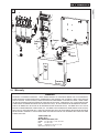
Power
Tankless Electric Water Heater
with electronic temperature control
On: unit operating
Off: unit off
S
C
A
L
D
I
N
G
D
A
N
G
E
R
H
a
n
d
W
a
s
h
i
n
g
R
e
s
i
d
e
n
t
i
a
l
U
s
e
C
o
m
m
e
r
c
i
a
l
O
n
l
y
Blinking: maximum power,
less than set point temp.
Steady: unit operating
Off: unit off
H
a
n
d
W
a
s
h
i
n
g
|
R
e
s
i
d
e
n
t
i
a
l
U
s
e
|
C
o
m
m
e
r
c
i
a
l
O
n
l
y
S
C
A
L
D
I
N
G
D
A
N
G
E
R
Tankless Electric Water Heater
with electronic temperature control
°F °C
The TEMPRA series is
tested and certified by WQA
against NSF/ANSI 372 for
“lead free“ compliance.

– 2 –
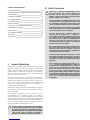
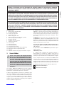
1. General Information
Read this entire manual. Failure to follow all the guides,
instructions and rules could cause personal injury or property
damage. Improper installation, adjustment, alteration, service
and use of this unit can result in serious injury.
This unit must be installed by a licensed electrician and
plumber. The installation must comply with all national, state
and local plumbing and electric codes. Proper installation is
the responsibility of the installer. Failure to comply with the
installation and operating instructions or improper use voids the
warranty.
Save these instructions for future reference. Installer should leave
these instructions with the consumer.
If you have any questions regarding the installation, use or
operation of this water heater, or if you need any additional
installation manuals, please call our technical service line at 800-
582-8423 (USA and Canada only). If you are calling from outside
the USA or Canada, please call USA 413-247-3380 and we will
refer you to a qualified Stiebel Eltron service representative in
your area.
! THIS IS THE SAFETY ALERT SYMBOL. IT IS USED TO ALERT
YOU TO POTENTIAL PERSONAL INJURY HAZARD. OBEY
ALL SAFETY MESSAGES THAT FOLLOW THIS SYMBOL TO
AVOID POSSIBLE INJURY OR DEATH.
S1 Safety Precautions
! PLEASE READ AND FOLLOW THESE INSTRUCTIONS.
FAILURE TO FOLLOW THESE INSTRUCTIONS COULD
RESULT IN SERIOIUS BODILY INJURY OR DEATH.
THE UNIT MUST BE INSTALLED BY A LICENSED ELECTRICIAN
AND PLUMBER. THE INSTALLATION MUST COMPLY
WITH ALL NATIONAL, STATE AND LOCAL PLUMBING AND
ELECTRIC CODES.
SERVICE OF THE UNIT MUST BE PERFORMED BY QUALIFIED
SERVICE TECHNICIANS.
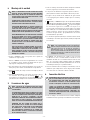
BEFORE PROCEEDING WITH ANY INSTALLATION,
ADJUSTMENT, ALTERATION, OR SERVICE OF THIS UNIT
ALL CIRCUIT BREAKERS AND DISCONNECT SWITCHES
SERVICING THE UNIT MUST BE TURNED OFF. FAILURE
TO DO SO COULD RESULT IN SERIOUS PERSONAL INJURY
OR DEATH.
NEVER REMOVE THE UNIT'S COVER UNLESS THE
ELECTRICITY SERVICING THE UNIT IS TURNED OFF.
FAILURE TO DO SO COULD RESULT IN PERSONAL INJURY
OR DEATH.
THE UNIT MUST BE PROPERLY GROUNDED. FAILURE TO
ELECTRICALLY GROUND THE PRODUCT COULD RESULT IN
SERIOUS PERSONAL INJURY OR DEATH.
DANGER: WATER TEMPERATURES OVER 125°F CAN
CAUSE SEVERE BURNS INSTANTLY OR DEATH FROM
SCALDING. A HOT WATER SCALDING POTENTIAL EXISTS
IF THE THERMOSTAT ON THE UNIT IS SET TOO HIGH.
HOUSEHOLDS WITH SMALL CHILDREN, DISABLED OR
ELDERLY PERSONS MAY REQUIRE THAT THE THERMOSTAT
BE SET AT 120°F OR LOWER TO PREVENT POSSIBLE INJURY
FROM HOT WATER.
ENGLISH TABLE OF CONTENTS
1. General Information _____________________________________________2
S1 Safety Precautions _______________________________________________2
2. Table showing temperature increase above ambient water
temperature_______________________________________________________3
3. General ____________________________________________________________7
4. Mounting the unit ________________________________________________7
5. Water connections _______________________________________________8
6. Electrical connection _____________________________________________8
7. Initial settings ____________________________________________________9
8. Putting the water heater into operation _______________________9
9. Normal maintenance _____________________________________________9
10. Technical Data ____________________________________________________9
11. Troubleshooting ________________________________________________ 10
12. Spare parts _____________________________________________________ 10
13. Warranty ________________________________________________________ 11

– 3 –
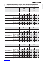
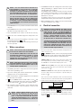
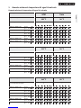
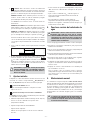
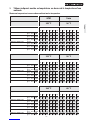
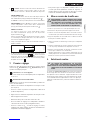
2. Table showing temperature increase above ambient water temperature
Maximum temperature increase above ambient water temperaturetLegend to figures
Warm water outlet temperature
140 °F 60 °C
TEMPRA 12 B / TEMPRA 12 Plus @ 208 V 9 kW 0.61 0.76 0.97 1.36 2.27 6.61 2.30 2.86 3.68 5.16 8.59 25.00
@ 220 - 240 V 12 kW 0.81 1.01 1.30 1.82 3.03 6.61 3.07 3.82 4.91 6.87 11.46 25.00
TEMPRA 15 B / TEMPRA 15 Plus @ 208 V 10,8 kW 0.73 0.91 1.17 1.63 2.72 6.61 2.76 3.44 4.42 6.19 10.31 25.00
@ 220 - 240 V 14.4 kW 0.97 1.21 1.56 2.18 3.63 6.61 3.68 4.58 5.89 8.25 13.75 25.00
TEMPRA 20 B / TEMPRA 20 Plus @ 208 V 14.4 kW 0.97 1.21 1.56 2.18 3.63 6.61 3.68 4.58 5.89 8.25 13.75 25.00
@ 220 - 240 V 19.2 kW 1.30 1.61 2.08 2.91 4.84 6.61 4.91 6.11 7.86 11.00 18.33 25.00
TEMPRA 24 B / TEMPRA 24 Plus @ 208 V 18 kW 1.22 1.51 1.95 2.72 4.54 6.61 4.60 5.73 7.36 10.31 17.18 25.00
@ 220 - 240 V 24 kW 1.62 2.02 2.59 3.63 6.05 6.61 6.14 7.64 9.82 13.75 22.91 25.00
TEMPRA 29 B / TEMPRA 29 Plus @ 208 V 21.6 kW 1.46 1.82 2.33 3.27 5.45 6.61 5.52 6.87 8.84 12.37 20.62 25.00
@ 220 - 240 V 28.8 kW 1.95 2.42 3.11 4.36 6.61 6.61 7.36 9.16 11.78 16.50 25.00 25.00
TEMPRA 36 B / TEMPRA 36 Plus @ 208 V 27 kW 1.82 2.27 2.92 4.09 6.61 6.61 6.90 8.59 11.05 15.47 25.00 25.00
@ 220 - 240 V 36 kW 2.43 3.03 3.89 5.45 6.61 6.61 9.21 11.46 14.73 20.62 25.00 25.00
Cold water inlet temperature °F °C
39 59 77 95 113 131 4 15 25 35 45 55
Warm water outlet temperature
113 °F 45 °C
TEMPRA 12 B / TEMPRA 12 Plus @ 208 V 9 kW 0,83 1,14 1,70 3,41 6,61 3,14 4,30 6,44 12,89 25,00
@ 220 - 240 V 12 kW 1,11 1,51 2,27 4,54 6,61 4,19 5,73 8,59 17,18 25,00
TEMPRA 15 B / TEMPRA 15 Plus @ 208 V 10,8 kW 1,00 1,36 2,04 4,09 6,61 3,77 5,16 7,73 15,47 25,00
@ 220 - 240 V 14.4 kW 1,33 1,82 2,72 5,45 6,61 5,03 6,87 10,31 20,62 25,00
TEMPRA 20 B / TEMPRA 20 Plus @ 208 V 14.4 kW 1,33 1,82 2,72 5,45 6,61 5,03 6,87 10,31 20,62 25,00
@ 220 - 240 V 19.2 kW 1,77 2,42 3,63 6,61 6,61 6,71 9,16 13,75 25,00 25,00
TEMPRA 24 B / TEMPRA 24 Plus @ 208 V 18 kW 1,66 2,27 3,41 6,61 6,61 6,29 8,59 12,89 25,00 25,00
@ 220 - 240 V 24 kW 2,21 3,03 4,54 6,61 6,61 8,38 11,46 17,18 25,00 25,00
TEMPRA 29 B / TEMPRA 29 Plus @ 208 V 21.6 kW 1,99 2,72 4,09 6,61 6,61 7,54 10,31 15,47 25,00 25,00
@ 220 - 240 V 28.8 kW 2,66 3,63 5,45 6,61 6,61 10,06 13,75 20,62 25,00 25,00
TEMPRA 36 B / TEMPRA 36 Plus @ 208 V 27 kW 2,49 3,41 5,11 6,61 6,61 9,43 12,89 19,33 25,00 25,00
@ 220 - 240 V 36 kW 3,32 4,54 6,61 6,61 6,61 12,57 17,18 25,00 25,00 25,00
Cold water inlet temperature °F °C
39 59 77 95 113 131 4 15 25 35 45 55
Warm water flow rate GPM l/min
Warm water outlet temperature 105 °F 40 °C
TEMPRA 12 B / TEMPRA 12 Plus @ 208 V 9 kW 0,95 1,36 2,27 6,61 3,58 5,16 8,59 25,00
@ 220 - 240 V 12 kW 1,26 1,82 3,03 6,61 4,77 6,87 11,46 25,00
TEMPRA 15 B / TEMPRA 15 Plus @ 208 V 10,8 kW 1,14 1,63 2,72 6,61 4,30 6,19 10,31 25,00
@ 220 - 240 V 14.4 kW 1,51 2,18 3,63 6,61 5,73 8,25 13,75 25,00
TEMPRA 20 B / TEMPRA 20 Plus @ 208 V 14.4 kW 1,51 2,18 3,63 6,61 5,73 8,25 13,75 25,00
@ 220 - 240 V 19.2 kW 2,02 2,91 4,84 6,61 7,64 11,00 18,33 25,00
TEMPRA 24 B / TEMPRA 24 Plus @ 208 V 18 kW 1,89 2,72 4,54 6,61 7,16 10,31 17,18 25,00
@ 220 - 240 V 24 kW 2,52 3,63 6,05 6,61 9,55 13,75 22,91 25,00
TEMPRA 29 B / TEMPRA 29 Plus @ 208 V 21.6 kW 2,27 3,27 5,45 6,61 8,59 12,37 20,62 25,00
@ 220 - 240 V 28.8 kW 3,03 4,36 6,61 6,61 11,46 16,50 25,00 25,00
TEMPRA 36 B / TEMPRA 36 Plus @ 208 V 27 kW 2,84 4,09 6,61 6,61 10,74 15,47 25,00 25,00
@ 220 - 240 V 36 kW 3,78 5,45 6,61 6,61 14,32 20,62 25,00 25,00
Cold water inlet temperature °F °C
39 59 77 95 113 131 4 15 25 35 45 55
English

– 4 –
Made in Germany
Power
Tankless Electric Water Heater
with electronic temperature control
On: unit operating
Off: unit off
S
C
A
L
D
I
N
G
D
A
N
G
E
R
H
a
n
d
W
a
s
h
i
n
g
R
e
s
i
d
e
n
t
i
a
l
U
s
e
C
o
m
m
e
r
c
i
a
l
O
n
l
y
Blinking: maximum power,
less than set point temp.
Steady: unit operating
Off: unit off
H
a
n
d
W
a
s
h
i
n
g
|
R
e
s
i
d
e
n
t
i
a
l
U
s
e
|
C
o
m
m
e
r
c
i
a
l
O
n
l
y
S
C
A
L
D
I
N
G
D
A
N
G
E
R
Tankless Electric Water Heater
with electronic temperature control
°F °C
8 5/8 (220)2 9/16 (65)
16 5/8 (420)4 (102)
14 1/2 (369)
11/16 (17,5)
4 5/8 (117)
TEMPRA 12 - 36 B
°
F
|
C
o
m
m
e
e
e
e
r
r
r
r
r
r
r
r
r
c
c
i
i
a
a
a
a
a
a
a
a
a
l
O
n
l
S
C
A
L
D
I
I
I
I
I
I
NN
N
N
N
N
N
N
N
N
N
G
G
D
D
D
D
D
D
D
D
D
A
A
A
A
A
N
G
E
R
1
3
2
A
B
26_02_02_0875
TEMPRA 12 - 36 Plus
4
TEMPRA 12 B / TEMPRA 12 Plus
TEMPRA 29, 36 B
TEMPRA 29, 36 Plus
5
8
12
9
13
TEMPRA 15, 20, 24 B
TEMPRA 15, 20, 24 Plus
7
er
n
t
r
ol
3
1
2.1
11
26_02_02_0874
26_02_02_0873 26_02_02_0873
26_02_02_0873
10
6


– 6 –
H
I
OFF
ON
OFF
ON
2
TEMPRA 12 B
TEMPRA 12 Plus
OFF
ON
OFF
ON
OFF
ON
OFF
ON
OFF
ON
OFF
ON
OFF
ON
OFF
ON
OFF
ON
OFF
ON
1
26_02_02_0568
26_02_02_0568
26_02_02_0568 26_02_02_0881
26_02_02_0881
26_02_02_0881
TEMPRA 15, 20, 24 B
TEMPRA 15, 20, 24 Plus
TEMPRA 29, 36 B
TEMPRA 29, 36 Plus
85_02_02_0001
TEMPRA 36 B
TEMPRA 36 Plus
TEMPRA 24 B
TEMPRA 24 Plus
TEMPRA 29 B
TEMPRA 29 Plus
TEMPRA 15/20 B
TEMPRA 15/20 Plus
TEMPRA 12 B
TEMPRA 12 Plus
CKT 1 CKT 2 CKT 3 CKT 1 CKT 2 CKT 3
CKT 1 CKT 2 CKT 1
CKT 1 CKT 2
642
531
642
531
642
531
42
51
42
51
42
51
642
531
642
531
642
531
42
51
42
51
6
4
2
5
3
1
6
11/12
5
4
9/10
3
2
7/8
1
13
6
11/12
5
4
9/10
3
2
7/8
1
13
6
11/12
5
4
9/10
3
2
7/8
1
13
6
11/12
5
4
9/10
3
2
7/8
1
13
6
11/12
5
4
9/10
3
2
7/8
1
13
4
2
5
1
4
2
5
1
6
4
2
5
3
1
6
4
2
5
3
1
14 15 14 15
14 15 14 15 14 15
CKT 1 CKT 2 CKT 3 CKT 1 CKT 2 CKT 1

– 7 –
English
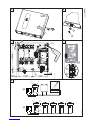
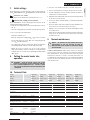
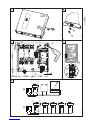
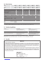
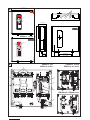
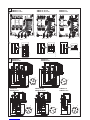
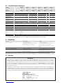
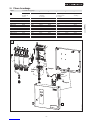
Legend to figures
1 Temperature adjustment knob
2 Temperature scale
2.1 Temperature display
3 "Power" light
4 Knock-outs for wires
5 Safety thermal cut out
6 Outlet temperature sensor
7 Wiring block
8 Electronic control unit
9 Heating system
10 Flow sensor
11 Motor-operated valve
12 Cold water connection
13 Hot water connection
14 Hot valve (left)
15 Cold valve (right)
16 Sink
17 Water supply line for faucet/tap installation
3. General
! DANGER: WATER TEMPERATURES OVER 125 °F CAN
CAUSE SEVERE BURNS INSTANTLY OR DEATH FROM
SCALDING. A HOT WATER SCALDING POTENTIAL EXISTS
IF THE THERMOSTAT ON THE UNIT IS SET TOO HIGH.
HOUSEHOLDS WITH SMALL CHILDREN, DISABLED OR
ELDERLY PERSONS MAY REQUIRE THAT THE THERMOSTAT
BE SET AT 120 °F OR LOWER TO PREVENT POSSIBLE
INJURY FROM HOT WATER.
The TEMPRA B and TEMPRA Plus units are designed to supply hot water
for a house, apartment or certain commercial applications. Unlike a
conventional storage type water heater the TEMPRA tankless water heater
does not store hot water. Instead, water is heated instantaneously as it
flows through the unit. The TEMPRA offers greater energy efficiency than
storage type water heaters due to the absence of stand-by losses and
reduced hot water pipe runs.
The input of heat into the water is controlled electronically. The TEMPRA
will deliver any water temperature between 86 °F (30 °C) and 140 °F (60 °C).
Please set the desired temperature using the knob on the front cover. The
TEMPRA Plus Temperature adjustment knob can be set to: OFF, 86...140 °F
(30...60 °C).
The TEMPRA B has a °F and a °C scale. The output temperature of the
TEMPRA Plus is shown in the digital display in °F or °C units. (°F or °C units
can be selected during installation, factory setting: °F). The maximum
temperature is electronically limited to 140 °F (60 °C).
For reasons of appliance efficiency and durability (scaling), the
optimum temperature setting lies between 86 °F (30 °C) and
120 °F (50 °C).
The outlet temperature of the TEMPRA Plus can be limited (see "Initial
settings").
TEMPRA B units:
In case the "Power” LED is flashing while the unit operates, the water
flow rate exceeds the heating capacity of the unit. Reduce the hot water
flow rate in order to let the unit achieve the set point temperature.
In case you have questions regarding the way you plan to use the TEMPRA
unit, please call our technical service line at 800-582-8423 (USA and
Canada). For service outside the U.S. and Canada, please call us at USA
413-247-3380. You can also e-mail us at info@stiebel-eltron-usa.com or
fax us at USA 413-247-3369.
The TEMPRA can be used for the following applications.
G
1
Typical residential installation
G
2
Typical commercial installation
4. Mounting the unit
! NOTICE: UNIT MUST BE INSTALLED IN A VERTICAL
POSITION WITH THE WATER FITTINGS POINTING
DOWNWARD.
WARNING: DO NOT INSTALL UNIT WHERE IT WOULD
ROUTINELY BE SPLASHED WITH WATER. ELECTRIC SHOCK
MAY RESULT.
CAUTION: HOT WATER OUTLET PIPES LEAVING UNIT CAN
BE HOT TO THE TOUCH. INSULATION MUST BE USED FOR
HOT WATER PIPES BELOW 36" DUE TO BURN RISK TO
CHILDREN.
THIS MANUAL MUST BE READ CAREFULLY BEFORE ATTEMPTING TO INSTALL THE TEMPRA WATER HEATER.
IF YOU DO NOT FOLLOW THE SAFETY RULES OR THE INSTRUCTIONS OUTLINED IN THIS MANUAL, THE UNIT
MAY NOT OPERATE PROPERLY AND IT COULD CAUSE PROPERTY DAMAGE, SERIOUS BODILY INJURY AND/
OR DEATH.
STIEBEL ELTRON, INC. WILL NOT BE LIABLE FOR ANY DAMAGES BECAUSE OF FAILURE TO COMPLY WITH THE
INSTALLATION AND OPERATING INSTRUCTIONS OUTLINED IN THIS MANUAL OR BECAUSE OF IMPROPER USE.
IMPROPER USE INCLUDES THE USE OF THIS APPLIANCE TO HEAT ANY LIQUID OTHER THAN WATER. FAILURE
TO COMPLY WITH THE INSTALLATION AND OPERATING INSTRUCTIONS OR IMPROPER USE VOIDS WARRANTY.
NEVER REMOVE THE UNIT’S COVER UNLESS THE ELECTRICITY IS TURNED OFF.
IF YOU HAVE ANY QUESTIONS REGARDING THE INSTALLATION OR OPERATION OF THIS WATER HEATER, OR
IF YOU NEED ANY ADDITIONAL INSTALLATION MANUALS, PLEASE CALL OUR TECHNICAL SERVICE LINE ON
800-582-8423 (USA AND CANADA ONLY). IF YOU ARE CALLING FROM OUTSIDE THE U.S. OR CANADA, PLEASE
CALL USA 413-247-3380 AND WE WILL REFER YOU TO A QUALIFIED STIEBEL ELTRON SERVICE REPRESENTATIVE
IN YOUR AREA.

– 8 –
! NOTICE: THIS UNIT SHOULD NOT BE INSTALLED IN A
LOCATION WHERE IT MAY BE EXPOSED TO FREEZING
TEMPERATURES (LESS THAN 36 °F). IF THE UNIT MAY
BE SUBJECT TO FREEZING TEMPERATURES ALL WATER
MUST BE DRAINED FROM THE UNIT. FAILURE TO COMPLY
WITH THIS INSTRUCTION VOIDS ALL WARRANTIES.
THE UNIT SHOULD BE LOCATED IN AN AREA WHERE
WATER LEAKAGE FROM THE UNIT OR CONNECTIONS
WILL NOT RESULT IN DAMAGE TO THE AREA ADJACENT
TO THE UNIT. IF SUCH A LOCATION CANNOT BE AVOIDED
IT IT RECOMMENDED THAT A DRAIN PAN BE INSTALLED
UNDER THE UNIT.
1. Install TEMPRA as close as possible to the main hot water draw-
off points.
2. Install TEMPRA in a frost free area. If frost might occur, remove
unit before freezing temperatures set in.
3. Leave a minimum of 5" of clearance on all sides for servicing.
4. Remove the cover screw with chopper disc and open the cover
C .
5. Mount unit securely to wall by putting at least three screws
through mounting holes E
1
-
3
.
Screws and plastic wall anchors for mounting on masonry or
wood are provided.
5. Water connections
! NOTICE: EXCESSIVE HEAT FROM SOLDERING ON COPPER
PIPES NEAR THE TEMPRA MAY CAUSE DAMAGE.
THE COLD WATER CONNECTION TO THE UNIT MUST BE
DISCONNECTED PERIODICALLY IN ORDER TO CLEAN
THE FILTER SCREEN. IT IS REQUIRED TO USE WATER
CONNECTIONS THAT ARE EASILY DETACHABLE SUCH AS
BRAIDED STEEL FLEX CONNECTORS.
! NOTICE: HARD WATER OR WATER WITH A HIGH MINERAL
COUNT MAY DAMAGE THE UNIT. DAMAGE TO THE UNIT
CAUSED BY SCALE OR A HIGH MINERAL COUNT IS NOT
COVERED UNDER THE WARRANTY.
1. All plumbing work must comply with national and applicable
state and local plumbing codes.
2. A pressure reducing valve must be installed if the cold water
supply pressure exceeds 150 PSI (10 bar).
3. Make certain that the cold water supply line has been flushed
to remove any scale and dirt.
4. D Also, the TEMPRA unit has a built in filter screen
1
that
should be cleaned from time to time. Clean screen and put the
screen and the washer
2
back into their original position.
5. The cold water connection (inlet) is on the right side of the
unit, and the hot water connection (outlet) is on the left side
of the unit.
6.
! NOTICE: TANKLESS WATER HEATERS SUCH AS THE
TEMPRA ARE NOT REQUIRED TO BE EQUIPPED WITH
A PRESSURE AND TEMPERATURE RELIEF VALVE
(P&T). IF THE LOCAL INSPECTOR WILL NOT PASS
THE INSTALLATION WITHOUT A P&T, IT SHOULD BE
INSTALLED ON THE HOT WATER OUTLET SIDE OF THE
UNIT.
7. The TEMPRA on the hot side is designed for connection to copper
tubing, PEX tubing or a braided stainless steel hose with a
3/4" NPT female tapered thread.
The plumbing on the cold water inlet side needs to be such that
it can easily be removed to allow access to the inlet filter screen.
The easiest way to achieve this is to us a stainless steel
braided hose connector.
If soldering near the unit is necessary, please direct the flame
away from the housing of the unit in order to avoid damage.
8. When all plumbing work is completed, check for leaks and take
corrective action before proceeding.
6. Electrical connection
! WARNING: BEFORE BEGINNING ANY WORK ON THE
ELECTRIC INSTALLATION, BE SURE THAT MAIN BREAKER
PANEL SWITCHES ARE "OFF" TO AVOID ANY DANGER OF
ELECTRIC SHOCK. ALL MOUNTING AND PLUMBING MUST
BE COMPLETED BEFORE PROCEEDING WITH ELECTRICAL
HOOK-UP. WHERE REQUIRED BY LOCAL, STATE OR
NATIONAL ELECTRICAL CODES THE CIRCUITS SHOULD
BE EQUIPPED WITH A "GROUND FAULT INTERRUPTER".
THE UNIT MUST BE PROPERLY GROUNDED IN ACCORDANCE
WITH STATE AND LOCAL CODES, OR IN ABSENCE OF SUCH
CODES, IN ACCORDANCE WITH NATIONAL ELECTRIC
CODE OR THE CANADIAN ELECTRIC CODE. FAILURE TO
ELECTRICALLY GROUND THE PRODUCT COULD RESULT IN
SERIOUS PERSONAL INJURY OR DEATH.
1. All electrical work must comply with national and applicable state
and local electrical codes.
2. H The TEMPRA should be connected to properly grounded
dedicated branch circuits of proper voltage rating. Ground must
be brought to the "Ground" at the circuit breaker panel.
TEMPRA 12 B/Plus: These units can be connected to a single circuit.
Use a supply cable protected by a double pole breaker (see
2
).
The TEMPRAS 15 to 36 must have multiple power sources.
TEMPRA 15, 20 or 24 B/Plus: These units require two independant
circuits. Use two supply cables protected by two separate double
pole breakers (see
2
).
TEMPRA 29 or 36 B/Plus These units require three independant circuits.
Use three supply cables protected by three separate double pole
breakers (see
2
).
Please refer to the technical data table for the correct wire and circuit
breaker size. In all cases, make sure that the unit is properly grounded.
3. Cut the electrical connection cable to length and strip.
15 (380)
26_02_02_0893
4. The wire must be fed through the knock-outs located between the
hot and cold water connections A , H
1
. The "live" wires must
be connected to the slots on the terminal block marked L1 and L2.
The ground wire must be connected to slot marked with the ground
symbol (see I ) .

– 9 –
English
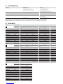
10. Technical Data
Model `BTVŨĜŝ `BTVŨĜÑ `BTVŨŝƃ `BTVŨŝÔ `BTVŨŝĎ `BTVŨŗō
Mat. no. ŝŝŗÔŝƃ ŝŝŗÔŝĜ ŝŝŗÔŝŝ ŝŝŗÔŝÔ ŝŗŝÄÄÑ ŝŗŝÄÄō
Model `BTVŨĜŝŨTùşń `BTVŨĜÑŨTùşń `BTVŨŝƃŨTùşń `BTVŨŝÔŨTùşń `BTVŨŝĎŨTùşń `BTVŨŗōŨTùşń
Mat. no. ŝŝÔĜĎō ŝŝÔĜĎŌ ŝŝÔĜĎÄ ŝŝÔĜĎĎ ŝŝŗÔŝÑ ŝŝŗÔŝō
Phase 111111
Voltage V208 240 208 240 208 240 208 240 208 240 208 240
Wattage kW 912 10.8 14.4 14.4 19.2 18 24 21.6 28.8 27 36
Max. amp, load A44 50 2 x 26 2 x 30 2 x 35 2 x 40 2 x 44 2 x 50 3 x 35 3 x 40 3 x 44 3 x 50
Min. required circuit
breaker size
A 60 60 2 x 40 2 x 40 2 x 50 2 x 50 2 x 60 2 x 60 3 x 50 3 x 50 3 x 60 3 x 60
Required wire size AWG COPPER 6 6 2 x 8 2 x 8 2 x 8 2 x 8 2 x 6 2 x 6 3 x 8 3 x 8 3 x 6 3 x 6
Inlet temperature, max. °F (°C) 131 (55)
Water flow to activate unit tGPM (tl/min) 0.37 (1.4) 0.50 (1.9) 0.50 (1.9) 0.50 (1.9) 0.77 (2.9) 0.77 (2.9)
Nominal water volume GAL (l) 0.13 (0.5) 0.26 (1.0) 0.26 (1.0) 0.26 (1.0) 0.39 (1.5) 0.39 (1.5)
Working pressure, max. PSI (bar) 145 (10)
Tested to pressure PSI (bar) 290 (20)
Weight lbs. (kg) 13.5 (6.1) 16.1 (7.3) 16.1 (7.3) 16.1 (7.3) 19.0 (8.6) 19.0 (8.6)
Dimensions
height
depth
width
inch (mm)
14 1/2 (369)
4 5/8 (117)
16 5/8 (420)
Water connections NPT 3/4"
– Tankless water heaters are considered a non-continuous load – Conductors should be sized to maintain a voltage drop of less than 3 % under load
7. Initial settings
Check whether the set value transducer cable is plugged into the
slot TSoll A1 (TEMPRA B) or TSoll D (TEMPRA Plus) on the main PCB.
F
1
Selection of °F or °C units
- Set jumper on the dial-printed circuit board to °F or °C.
- F
2
Activate anti-scalding protection function
On the TEMPRA Plus, an anti-scalding protection function can be
activated by two different methods.
1. Limit the outlet temperature to the fixed temperature of 109°F
(43 °C).
- Insert the coding plug into position Tred (reduced temperature).
2. Select a specific outlet temperature
- Switch the appliance 'live'.
- Open the casing so that coding plug Tmax / Tred becomes accessible.
- Set the temperature selector to "OFF". The coding plug must be
set to Tmax (standard delivery).
- Set coding plug to Tred; the setting mode will be activated and
the flashing display shows the current temperature limit.
- Within the next 30 seconds, you can select the required
temperature (display continues to flash). The setting mode will
terminate after 30 seconds; the programming unit will display
"OFF" again.
8. Putting the water heater into
operation
! WARNING: OPEN HOT WATER FAUCET FOR A FEW
MINUTES UNTIL WATER FLOW IS CONTINUOUS AND ALL
AIR IS PURGED FROM WATER PIPES. THE UNIT’S COVER
MUST BE INSTALLED BEFORE THE CIRCUIT BREAKERS ARE
TURNED ON.
1. Close the cover and fix it using the screw with chopper disc.
2. Turn on circuit breakers to bring electrical power to the unit.
3. Turn the temperature selector clockwise and anti-clockwise, to
calibrate the set value transducer.
4. Adjust the water temperature to the desired level using the knob
on the front cover of the unit.
5. Turn on hot water and wait twenty seconds until temperature
has stabilized.
6. Check the water temperature with your hand and make sure
that it does not feel too hot. Reduce if necessary.
7. Explain to the user how the unit works and familiarise him
or her with its use.
Advise the user about possible hazards (hot water temperature
up to 140 °F / 60 °C). Hand over these instructions, to be kept
for future reference.
9. Normal maintenance
! NOTICE: THE TEMPRAS DO NOT CONTAIN ANY PARTS
SERVICEABLE BY THE LAY PERSON. IN CASE OF
MALFUNCTION PLEASE CONTACT A LICENSED PLUMBER
OR ELECTRICIAN.
STIEBEL ELTRON TEMPRA tankless water heaters are designed
for a very long service life. Actual life expectancy will vary with
water quality and use. The unit itself does not require any regular
maintenance. However, to ensure consistent water flow, it is
recommended to periodically remove scale and dirt that may build
up at the aerator of the faucet(s), the filter screen in the unit, or
in the shower head.

– 10 –
Model Spare part No.
J
8 9 10 11 12 13 14
Plumbing
connection 3/4"
Advanced Flow
Control
Electronic temp.
control
Jumpers Temperature
sensor
Filter screen Set point case
TEMPRA 12 B 278698 --- 286359 --- 280677 056755 280730
TEMPRA 15 B 278698 --- 286359 --- 280677 056755 280730
TEMPRA 20 B 278698 --- 286359 --- 280677 056755 280730
TEMPRA 24 B 278698 --- 286359 --- 280677 056755 280730
TEMPRA 29 B 278698 --- 286359 --- 280677 056755 280730
TEMPRA 36 B 278698 --- 286359 --- 280677 056755 280730
TEMPRA 12 Plus 278698 220502 286372 283455 280677 056755 280730
TEMPRA 15 Plus 278698 220502 286372 283455 280677 056755 280730
TEMPRA 20 Plus 278698 220502 286372 283455 280677 056755 280730
TEMPRA 24 Plus 278698 220502 286372 283455 280677 056755 280730
TEMPRA 29 Plus 278698 220502 286372 283455 280677 056755 280730
TEMPRA 36 Plus 278698 220502 286372 283455 280677 056755 280730
Model Spare part No.
J
15 16 17
Inlet pipe elbow Valve assembly Axis connection
plug
TEMPRA 12 B 278695 --- 254312
TEMPRA 15 B 278695 --- 254312
TEMPRA 20 B 278695 --- 254312
TEMPRA 24 B 278695 --- 254312
TEMPRA 29 B 278695 --- 254312
TEMPRA 36 B 278695 --- 254312
TEMPRA 12 Plus --- 280622 254312
TEMPRA 15 Plus --- 280622 254312
TEMPRA 20 Plus --- 280622 254312
TEMPRA 24 Plus --- 280622 254312
TEMPRA 29 Plus --- 280622 254312
TEMPRA 36 Plus --- 280622 254312
12. Spare parts
Model Spare part No.
J
1 2 3 4 5 6 7
Housing
Temp. control
knob
Wiring block Heating system Safety thermal
cut out
Electronic control
device
Flow sensor
TEMPRA 12 B 286356 254307 279998 286360 286369 286366 286461
TEMPRA 15 B 286356 254307 279997 286361 286369 286844 286461
TEMPRA 20 B 286356 254307 279997 286362 286369 286844 286461
TEMPRA 24 B 286356 254307 279997 286364 286369 286367 286461
TEMPRA 29 B 286356 254307 279996 286373 286369 296888 286461
TEMPRA 36 B 286356 254307 279996 286374 286369 296889 286461
TEMPRA 12 Plus 286370 254307 279998 286360 286369 286375 286461
TEMPRA 15 Plus 286370 254307 279997 286361 286369 286845 286461
TEMPRA 20 Plus 286370 254307 279997 286362 286369 286845 286461
TEMPRA 24 Plus 286370 254307 279997 286364 286369 286376 286461
TEMPRA 29 Plus 286370 254307 279996 286373 286369 286378 286461
TEMPRA 36 Plus 286370 254307 279996 286374 286369 286379 286461
11. Troubleshooting
Symptom TĒńńêù¼|şń¼ ZĒùşŒêĒĉ
No hot water
– circuit breakers off
– safety thermal cut-out tripped
– not enough flow rate to activate unit
– turn circuit breakers on
– reset safety thermal cut-out
– clean filter screen at unit
– clean faucet aerator or shower head
Not enough hot water – filter screen clogged – clean filter screen at unit
Water not hot enough
– water flow rate too high
– voltage too low
– reduce water flow rate until power light on front
cover stops blinking
– supply correct voltage to unit
If you are not able to resolve a problem please contact us toll free at 800-582-8423 before removing the unit from the wall.
STIEBEL ELTRON is happy to provide technical assistance. In most instances, we can resolve the problem over the phone.

– 11 –
English
13. Warranty
WARRANTY
RESIDENTIAL & COMMERCIAL WARRANTY: STIEBEL ELTRON WARRANTS TO THE ORIGINAL OWNER THAT THE INSTANTANEOUS
WATER HEATER WILL BE FREE FROM DEFECTS IN WORKMANSHIP AND MATERIALS FOR A PERIOD OF THREE YEARS FROM THE
DATE OF PURCHASE. SHOULD THE PART(S) PROVE TO BE DEFECTIVE UNDER NORMAL USE DURING THIS PERIOD, STIEBEL ELTRON,
INC. WILL BE RESPONSIBLE FOR REPLACEMENT OF THE DEFECTIVE PART(S) ONLY. STIEBEL ELTRON, INC. IS NOT RESPONSIBLE FOR
LABOR CHARGES TO REMOVE AND/OR REPLACE THE DEFECTIVE PART(S), OR ANY INCIDENTIAL OR CONSEQUENTIAL EXPENSES.
SHOULD THE OWNER WISH TO RETURN THE INSTANTANEOUS WATER HEATER FOR REPAIR, THE OWNER MUST FIRST SECURE
WRITTEN AUTHORIZATION FROM STIEBEL ELTRON, INC. THE OWNER SHALL BE REQUIRED TO SHOW PROOF OF PURCHASE DATE,
AND TO PAY ALL TRANSPORTATION COSTS TO RETURN THE DEFECTIVE PART(S) OR INSTANTANEOUS WATER HEATER FOR REPAIR
OR REPLACEMENT. WARRANTY IS VOID IF WATER HEATER HAS BEEN INSTALLED OR USED IMPROPERLY OR IF DESIGN HAS BEEN
ALTERED IN ANY WAY.
STIEBEL ELTRON, INC.
17 West Street
West Hatfield, MA 01088, USA
PHONE: 800-582-8423 or 413-247-3380
FAX: 413-247-3369
E-Mail info@stiebel-eltron-usa.com
www.stiebel-eltron-usa.com
J
Tempra
i
Tempra
Plus
Tempra
Tempra
Plus
5
12
7
9
15
13
2
3
6
10
11
4
Tempra
Tempra
P
l
us
1
0
11
1
16
14
17
8
26_02_02_0977
8

– 12 –
1. General Information
Es importante leer y cumplir cuidadosamente todas las indicaciones
del presente manual de servicio. De no seguir las indicaciones,
normas y reglas detalladas se pueden causar daños personal y/o
materiales. Errores, cambios de lo indicado en la instalación,
ajuste, alteraciones, tipo de servicio y uso de esta unidad pueden
provocar serios daños personales.
Se requiere que la instalación de esta unidad sea efectuada por
un electricista y plomero profesionales. Una vez terminada la
instalación debe cumplir con todas las normas y códigos locales
y nacionales. La adecuada instalación es responsabilidad del
usuario. El no cumplir con las instrucciones de instalación o el
uso inapropiado anula la garantía.
Este manual de instrucciones debe estar guardado para referencia.
El contratista instalador debe dejar este manual con el dueño/
usuario del equipo.
Si hay alguna(s) pregunta(s) sobre la instalación, uso o
funcionamiento de este calentador de agua, o si se requieren
copias adicionales de este manual, favor llamar a nuestro teléfono
de servicio (800) 582-8423 (solo en los EE.UU.AA y Canadá). Si Ud.
está ubicado afuera de los EE.UU.AA. y Canadá favor llamarnos al
teléfono ++ (413) 247-3380 y nosotros les dirigimos al centro de
servicio Stiebel Eltron autorizado más cercano.
! ESTE ES EL SIMBOLO / ADVERTENCIA DE SEGURIDAD!!!
SE UTILIZA PARA ALERTARLES DE RIESGOS Y PELIGROS
POTENCIALES REFERENTES A SU SEGURIDAD PERSONAL,
HAY QUE SEGUIR TODOS LOS MENSAJES DE ADVERTENCIA
PARA EVITAR POSIBLES LESIONES PERSONALES Y
PELIGROS QUE PUEDEN CAUSAR HASTA LA MUERTE.
ESPAÑOL ÍNDICE DE MATERIAS
1. General Information ___________________________________________ 12
2. Aumento máximo de temperatura del agua fría entrante _ 13
3. Generalidades __________________________________________________ 17
4. Montaje de la unidad __________________________________________ 18
5. Conexiones de agua ____________________________________________ 18
6. Conexión eléctrica______________________________________________ 18
7. Ajustes iniciales ________________________________________________ 19
8. Puesta en servicio del calentador de agua __________________ 19
9. Mantenimiento normal ________________________________________ 19
10. Datos técnicos __________________________________________________ 20
11. Solución de problemas ________________________________________ 20
12. Garantía _________________________________________________________ 20
13. Repuestos _______________________________________________________ 21
S1 Safety Precautions
! FAVOR LEER Y CUMPLIR CUIDADOSAMENTE TODAS
LAS INDICACIONES DEL PRESENTE MANUAL DE
SERVICIO. DE NO SEGUIR LAS INDICACIONES,
NORMAS Y REGLAS DETALLADAS SE PUEDEN CAUSAR
DAÑOS PERSONALES Y/O LA MUERTE.
LA INSTALACIÓN DE ESTA UNIDAD DEBE SER EFECTUADA
POR UN ELECTRICISTA Y PLOMERO PROFESIONAL. UNA
VEZ TERMINADA LA INSTALACIÓN DEBE CUMPLIR CON
TODAS LAS NORMAS Y CÓDIGOS LOCALES Y NACIONALES.
EL MANTENIMIENTO O REPARACIÓN DE ESTA UNIDAD
DEBE SER EFECTUADO POR UN TÉCNICO DEBIDAMENTE
CALIFICADO PARA EFECTUAR TAL SERVICIO.
HAY QUE DESCONECTAR / APAGAR TODOS LOS
INTERRUPTORES AUTOMÁTICOS, “BREAKERS”,
DISYUNTORES, Y CONEXIONES DANDO CARGA ELÉCTRICA
A LA UNIDAD ANTES DE PROCEDER CON CUALQUIER
INSTALACIÓN, AJUSTE, CAMBIO O PROCEDIMIENTO DE
SERVICIO. EL NO SEGUIR ESTE PROCESO SE CORRE LA
POSIBILIDAD DE LESIONES PERSONALES Y PELIGROS QUE
PUEDEN CAUSAR HASTA LA MUERTE.
NO SE PUEDE ABRIR O DESTAPAR LA UNIDAD A MENOS
QUE LA ELECTRICIDAD ALIMENTANDO LA UNIDAD ESTÁ
APAGADA. EL NO SEGUIR ESTE PROCESO SE CORRE LA
POSIBILIDAD DE LESIONES PERSONALES Y PELIGROS QUE
PUEDEN CAUSAR HASTA LA MUERTE.
ES INDISPENSABLE CONECTAR EL APARATO A LA TOMA
DE TIERRA DE LA INSTALACIÓN ELÉCTRICA. EL NO SEGUIR
ESTE PROCESO SE CORRE LA POSIBILIDAD DE LESIONES
PERSONALES Y PELIGROS QUE PUEDEN CAUSAR HASTA
LA MUERTE.
AGUA CALIENTE CON TEMPERATURA MAYOR DE 125°
F / 52° C PUEDE CAUSAR QUEMADURAS GRAVES DE
ESCALDADURA INSTANTÁNEAMENTE Y/O LA MUERTE.
EL RIESGO PARA QUEMADURAS DE ESCALDADURA
EXISTE SI EL CONTROL DEL TERMOSTATO DE LA UNIDAD
ESTA PUESTO EN UNA POSICIÓN DEMASIADO ALTA.
HOGARES CON INFANTES, NIÑOS PEQUEÑOS, PERSONAS
MINUSVÁLIDAS O ANCIANOS DEBEN OPTAR POR COLOCAR
LA TEMPERATURA DE AGUA CALIENTE SALIENTE A MENOS
DE 120° F (49° C) PARA EVITAR POSIBLES LESIONES POR
QUEMADURA.

– 13 –
Español
2. Aumento máximo de temperatura del agua fría entrante
Aumento máximo de temperatura del agua fría entrante
Temperatura del agua caliente
140 °F 60 °C
TEMPRA 12 B / TEMPRA 12 Plus @ 208 V 9 kW 0.61 0.76 0.97 1.36 2.27 6.61 2.30 2.86 3.68 5.16 8.59 25.00
@ 220 - 240 V 12 kW 0.81 1.01 1.30 1.82 3.03 6.61 3.07 3.82 4.91 6.87 11.46 25.00
TEMPRA 15 B / TEMPRA 15 Plus @ 208 V 10,8 kW 0.73 0.91 1.17 1.63 2.72 6.61 2.76 3.44 4.42 6.19 10.31 25.00
@ 220 - 240 V 14.4 kW 0.97 1.21 1.56 2.18 3.63 6.61 3.68 4.58 5.89 8.25 13.75 25.00
TEMPRA 20 B / TEMPRA 20 Plus @ 208 V 14.4 kW 0.97 1.21 1.56 2.18 3.63 6.61 3.68 4.58 5.89 8.25 13.75 25.00
@ 220 - 240 V 19.2 kW 1.30 1.61 2.08 2.91 4.84 6.61 4.91 6.11 7.86 11.00 18.33 25.00
TEMPRA 24 B / TEMPRA 24 Plus @ 208 V 18 kW 1.22 1.51 1.95 2.72 4.54 6.61 4.60 5.73 7.36 10.31 17.18 25.00
@ 220 - 240 V 24 kW 1.62 2.02 2.59 3.63 6.05 6.61 6.14 7.64 9.82 13.75 22.91 25.00
TEMPRA 29 B / TEMPRA 29 Plus @ 208 V 21.6 kW 1.46 1.82 2.33 3.27 5.45 6.61 5.52 6.87 8.84 12.37 20.62 25.00
@ 220 - 240 V 28.8 kW 1.95 2.42 3.11 4.36 6.61 6.61 7.36 9.16 11.78 16.50 25.00 25.00
TEMPRA 36 B / TEMPRA 36 Plus @ 208 V 27 kW 1.82 2.27 2.92 4.09 6.61 6.61 6.90 8.59 11.05 15.47 25.00 25.00
@ 220 - 240 V 36 kW 2.43 3.03 3.89 5.45 6.61 6.61 9.21 11.46 14.73 20.62 25.00 25.00
agua fría temperatura de entrada °F °C
39 59 77 95 113 131 4 15 25 35 45 55
Temperatura del agua caliente
113 °F 45 °C
TEMPRA 12 B / TEMPRA 12 Plus @ 208 V 9 kW 0,83 1,14 1,70 3,41 6,61 3,14 4,30 6,44 12,89 25,00
@ 220 - 240 V 12 kW 1,11 1,51 2,27 4,54 6,61 4,19 5,73 8,59 17,18 25,00
TEMPRA 15 B / TEMPRA 15 Plus @ 208 V 10,8 kW 1,00 1,36 2,04 4,09 6,61 3,77 5,16 7,73 15,47 25,00
@ 220 - 240 V 14.4 kW 1,33 1,82 2,72 5,45 6,61 5,03 6,87 10,31 20,62 25,00
TEMPRA 20 B / TEMPRA 20 Plus @ 208 V 14.4 kW 1,33 1,82 2,72 5,45 6,61 5,03 6,87 10,31 20,62 25,00
@ 220 - 240 V 19.2 kW 1,77 2,42 3,63 6,61 6,61 6,71 9,16 13,75 25,00 25,00
TEMPRA 24 B / TEMPRA 24 Plus @ 208 V 18 kW 1,66 2,27 3,41 6,61 6,61 6,29 8,59 12,89 25,00 25,00
@ 220 - 240 V 24 kW 2,21 3,03 4,54 6,61 6,61 8,38 11,46 17,18 25,00 25,00
TEMPRA 29 B / TEMPRA 29 Plus @ 208 V 21.6 kW 1,99 2,72 4,09 6,61 6,61 7,54 10,31 15,47 25,00 25,00
@ 220 - 240 V 28.8 kW 2,66 3,63 5,45 6,61 6,61 10,06 13,75 20,62 25,00 25,00
TEMPRA 36 B / TEMPRA 36 Plus @ 208 V 27 kW 2,49 3,41 5,11 6,61 6,61 9,43 12,89 19,33 25,00 25,00
@ 220 - 240 V 36 kW 3,32 4,54 6,61 6,61 6,61 12,57 17,18 25,00 25,00 25,00
agua fría temperatura de entrada °F °C
39 59 77 95 113 131 4 15 25 35 45 55
Flujo de agua caliente GPM l/min
Temperatura del agua caliente 105 °F 40 °C
TEMPRA 12 B / TEMPRA 12 Plus @ 208 V 9 kW 0,95 1,36 2,27 6,61 3,58 5,16 8,59 25,00
@ 220 - 240 V 12 kW 1,26 1,82 3,03 6,61 4,77 6,87 11,46 25,00
TEMPRA 15 B / TEMPRA 15 Plus @ 208 V 10,8 kW 1,14 1,63 2,72 6,61 4,30 6,19 10,31 25,00
@ 220 - 240 V 14.4 kW 1,51 2,18 3,63 6,61 5,73 8,25 13,75 25,00
TEMPRA 20 B / TEMPRA 20 Plus @ 208 V 14.4 kW 1,51 2,18 3,63 6,61 5,73 8,25 13,75 25,00
@ 220 - 240 V 19.2 kW 2,02 2,91 4,84 6,61 7,64 11,00 18,33 25,00
TEMPRA 24 B / TEMPRA 24 Plus @ 208 V 18 kW 1,89 2,72 4,54 6,61 7,16 10,31 17,18 25,00
@ 220 - 240 V 24 kW 2,52 3,63 6,05 6,61 9,55 13,75 22,91 25,00
TEMPRA 29 B / TEMPRA 29 Plus @ 208 V 21.6 kW 2,27 3,27 5,45 6,61 8,59 12,37 20,62 25,00
@ 220 - 240 V 28.8 kW 3,03 4,36 6,61 6,61 11,46 16,50 25,00 25,00
TEMPRA 36 B / TEMPRA 36 Plus @ 208 V 27 kW 2,84 4,09 6,61 6,61 10,74 15,47 25,00 25,00
@ 220 - 240 V 36 kW 3,78 5,45 6,61 6,61 14,32 20,62 25,00 25,00
agua fría temperatura de entrada °F °C
39 59 77 95 113 131 4 15 25 35 45 55

– 14 –
Made in Germany
Power
Tankless Electric Water Heater
with electronic temperature control
On: unit operating
Off: unit off
S
C
A
L
D
I
N
G
D
A
N
G
E
R
H
a
n
d
W
a
s
h
i
n
g
R
e
s
i
d
e
n
t
i
a
l
U
s
e
C
o
m
m
e
r
c
i
a
l
O
n
l
y
Blinking: maximum power,
less than set point temp.
Steady: unit operating
Off: unit off
H
a
n
d
W
a
s
h
i
n
g
|
R
e
s
i
d
e
n
t
i
a
l
U
s
e
|
C
o
m
m
e
r
c
i
a
l
O
n
l
y
S
C
A
L
D
I
N
G
D
A
N
G
E
R
Tankless Electric Water Heater
with electronic temperature control
°F °C
8 5/8 (220)2 9/16 (65)
16 5/8 (420)4 (102)
14 1/2 (369)
11/16 (17,5)
4 5/8 (117)
TEMPRA 12 - 36 B
°
F
|
C
o
m
m
e
e
e
e
r
r
r
r
r
r
r
r
r
c
c
i
i
a
a
a
a
a
a
a
a
a
l
O
n
l
S
C
A
L
D
I
I
I
I
I
I
NN
N
N
N
N
N
N
N
N
N
G
G
D
D
D
D
D
D
D
D
D
A
A
A
A
A
N
G
E
R
1
3
2
A
B
26_02_02_0875
TEMPRA 12 - 36 Plus
4
TEMPRA 12 B / TEMPRA 12 Plus
TEMPRA 29, 36 B
TEMPRA 29, 36 Plus
5
8
12
9
13
TEMPRA 15, 20, 24 B
TEMPRA 15, 20, 24 Plus
7
er
n
t
r
ol
3
1
2.1
11
26_02_02_0874
26_02_02_0873 26_02_02_0873
26_02_02_0873
10
6


– 16 –
H
I
OFF
ON
OFF
ON
2
TEMPRA 12 B
TEMPRA 12 Plus
OFF
ON
OFF
ON
OFF
ON
OFF
ON
OFF
ON
OFF
ON
OFF
ON
OFF
ON
OFF
ON
OFF
ON
1
26_02_02_0568
26_02_02_0568
26_02_02_0568 26_02_02_0881
26_02_02_0881
26_02_02_0881
TEMPRA 15, 20, 24 B
TEMPRA 15, 20, 24 Plus
TEMPRA 29, 36 B
TEMPRA 29, 36 Plus
85_02_02_0001
TEMPRA 36 B
TEMPRA 36 Plus
TEMPRA 24 B
TEMPRA 24 Plus
TEMPRA 29 B
TEMPRA 29 Plus
TEMPRA 15/20 B
TEMPRA 15/20 Plus
TEMPRA 12 B
TEMPRA 12 Plus
CKT 1 CKT 2 CKT 3 CKT 1 CKT 2 CKT 3
CKT 1 CKT 2 CKT 1
CKT 1 CKT 2
642
531
642
531
642
531
42
51
42
51
42
51
642
531
642
531
642
531
42
51
42
51
6
4
2
5
3
1
6
11/12
5
4
9/10
3
2
7/8
1
13
6
11/12
5
4
9/10
3
2
7/8
1
13
6
11/12
5
4
9/10
3
2
7/8
1
13
6
11/12
5
4
9/10
3
2
7/8
1
13
6
11/12
5
4
9/10
3
2
7/8
1
13
4
2
5
1
4
2
5
1
6
4
2
5
3
1
6
4
2
5
3
1
14 15 14 15
14 15 14 15 14 15
CKT 1 CKT 2 CKT 3 CKT 1 CKT 2 CKT 1

– 17 –
Español
Leyenda de cifras
1 Botón de ajuste de temperatura
2 Escala de temperatura
2.1 Pantalla de temperatura
3 Luz de alimentación
4 Orificios ciegos para cables
5 Disparo de la protección térmica de seguridad
6 Sensor de temperatura de salida
7 Bloque de cableado
8 Unidad de control electrónica
9 Sistema de calefacción
10 Sensor de flujo
11 Valvula motorizada
12 Conexión de agua fría
13 Conexión de agua caliente
14 Válvula del circuito de agua caliente (izquierda)
15 Válvula del circuito de agua fría (derecha)
16 Sumidero
17 Tubería de suministro de agua para instalación con grifo
3. Generalidades
! PELIGRO: AGUA CALIENTE CON TEMPERATURA MAYOR
DE 125 °F / 52 °C PUEDE CAUSAR QUEMADURAS GRAVES
DE ESCALDADURA INSTANTÁNEAMENTE Y/O LA MUERTE.
EL RIESGO PARA QUEMADURAS DE ESCALDADURA
EXISTE SI EL CONTROL DEL TERMOSTATO DE LA UNIDAD
ESTA PUESTO EN UNA POSICIÓN DEMASIADO ALTA.
HOGARES CON INFANTES, NIÑOS PEQUEÑOS, PERSONAS
MINUSVÁLIDAS O ANCIANOS DEBEN OPTAR POR COLOCAR
LA TEMPERATURA DE AGUA CALIENTE SALIENTE A MENOS
DE 120 °F (49 °C) PARA EVITAR POSIBLES LESIONES POR
QUEMADURA.
Las unidades TEMPRA B y TEMPRA Plus han sido diseñadas
para suministrar agua caliente para viviendas unifamiliares,
apartamentos o determinadas aplicaciones comerciales.
A diferencia del acumulador convencional, el calentador de agua
sin depósito TEMPRAS no almacena agua caliente. En lugar de
ello, el agua se calienta de forma instantánea a medida que pasa
a través de la unidad. El TEMPRAS ofrece mayor rendimiento
energético que los calentadores de agua de almacenamiento,
debido a la ausencia de pérdidas en stand-by y a unas longitudes
menores de tubería de agua caliente.
La entrada de calor en el agua se controla electrónicamente. El
TEMPRAS es capaz de proporcionar cualquier temperatura del
agua entre 86 °F (30 °C) y 140 °F (60 °C). Ajuste la temperatura
deseada utilizando el botón del panel delantero. El botón de ajuste
de temperatura TEMPRA Plus puede ajustarse en: OFF, 86...140 °F
(30...60 °C).
El TEMPRA B posee una escala en °F y °C. La temperatura de salida
del TEMPRA Plus se muestra en la pantalla digital en °F o °C. (las
unidades °F o °C pueden seleccionarse durante la instalación y de
fábrica viene ajustada la unidad °F). La temperatura máxima está
limitada electrónicamente a 140 °F (60 °C).
Por razones de eficiencia y vida útil (calcificación) del aparato, el
rango de ajuste óptimo de la temperatura está entre 30°C (86°F)
y 50°C (120°F).
La temperatura de salida del TEMPRA Plus puede limitarse (véase
"Ajustes iniciales").
TEMPRA B dispositivo:
Si el LED "Power" [alimentación] parpadea durante el
funcionamiento de la unidad, el caudal de agua supera la
capacidad de calefacción de la unidad. Reduzca el caudal de agua
caliente para que la unidad alcance la temperatura de consigna.
Si tiene cualquier duda sobre la utilización del TEMPRAS llame
a nuestro servicio técnico 800-582-8423 (EE.UU. y Canadá). Para
recibir servicio técnico fuera de los EE. UU. y Canadá, llámenos en
USA 413-247-3380. También puede enviarnos un e-mail a la dirección
info@stiebel-eltron-usa.com o un fax a los EE. UU. 413-247-3369.
El TEMPRA puede utilizarse para las siguientes aplicaciones.
G
1
Instalación residencial típica
G
2
Instalación comercial típica
LEA ATENTAMENTE ESTE MANUAL ANTES DE INSTALAR EL CALENTADOR DE AGUA TEMPRA. SI NO SIGUE LAS
NORMAS DE SEGURIDAD O LAS INSTRUCCIONES DEL PRESENTE MANUAL ES POSIBLE QUE LA UNIDAD NO
FUNCIONE ADECUADAMENTE Y PODRÍAN PRODUCIRSE DAÑOS MATERIALES, LESIONES CORPORALES GRAVES
E INCLUSO LA MUERTE.
STIEBEL ELTRON, INC. NO SE HACE RESPONSABLE DE NINGÚN DAÑO CAUSADO POR EL INCUMPLIMIENTO DE LAS
INSTRUCCIONES DE INSTALACIÓN Y OPERACIÓN INDICADAS EN EL PRESENTE MANUAL O DERIVADO DEL USO
INDEBIDO DE LA INSTALACIÓN. EL USO INDEBIDO ABARCA EL USO DE LA PRESENTE INSTALACIÓN PARA CALENTAR
CUALQUIER OTRO LÍQUIDO DISTINTO AL AGUA. SI NO OBSERVA LAS INSTRUCCIONES DE INSTALACIÓN Y OPERACIÓN
O SE HACE USO INDEBIDO DE LA INSTALACIÓN LA GARANTÍA QUEDARÁ ANULADA. NUNCA DEBE EXTRAER LA
TAPA DE LA UNIDAD A MENOS QUE SE HAYA CORTADO ANTES LA ALIMENTACIÓN ELÉCTRICA.
ANTE CUALQUIER DUDA RELACIONADA CON LA INSTALACIÓN U OPERACIÓN DEL PRESENTE CALENTADOR DE AGUA
O SI NECESITA CUALQUIER MANUAL DE INSTALACIÓN ADICIONAL, CONSULTE AL SERVICIO TÉCNICO EN EL NÚMERO
800-582-8423 (SÓLO EE.UU. Y CANADÁ) SI LLAMA DESDE FUERA DE LOS EE.UU. O CANADÁ LLAME AL NÚMERO
DE LOS EE.UU. 413-247-3380 Y LE REMITIREMOS A UN REPRESENTANTE CUALIFICADO DE SERVICIO TÉCNICO
STIEBEL ELTRON DE SU LOCALIDAD.

– 18 –
4. Montaje de la unidad
! NOTA: LA UNIDAD DEBE ESTAR INSTALADA EN POSICIÓN
VERTICAL CON LAS CONEXIONES DE AGUA MIRANDO
HACIA ABAJO. NO INSTALE LA UNIDAD EN LUGARES EN
LOS QUE PUEDA SUFRIR SALPICADURAS DE AGUA. PUEDE
SUFRIR UNA ELECTROCUCIÓN.
PELIGRO: NO SE PUEDE INSTALAR LA UNIDAD EN UN SITIO
DONDE HAY SALPICADURA DE AGUA. ES PARA EVITAR EL
RIESGO DE POSIBLE DESCARGA ELECTRICA.
PRECAUCION IMPORTANTE: LA TUBERIA SALIENTE DE
LA UNIDAD PUEDE ESTAR CALIENTE AL TOCARLA. LOS
TUBOS CON UNA ALTURA DE 36 PULGADAS (90 CM) O
MENOS TIENEN QUE SER RECUBIERTOS CON INSULACION
TERMICA PARA EVITAR QUEMADURAS A LOS NIÑOS.
AVISO IMPORTANTE: NO SE PUEDE INSTALAR LA UNIDAD
EN UN SITIO DONDE ESTE SUJETO A TEMPERATURAS
MENORES DE CERO °C (32 °F). SI LA UNIDAD ESTA SUJETA
A TEMPERATURAS QUE PERMITIRIAN LA CONGELACION
DEL AGUA HAY QUE DRENAR LA UNIDAD ANTES QUE
OCURRA TAL COSA. SI ESTO NO SE HACE EL CALENTADOR
PIERDE LA GARANTIA.
HAY QUE INSTALAR LA UNIDAD DONDE SE EVITE QUE
UNA POSIBLE FUGA DE AGUA DESDE LA UNIDAD O SUS
CONEXCIONES PUEDAN RESULTAR EN DAÑOS A LAS
AREAS CONTIGUAS. SI NO ES POSIBLE TAL COLOCACION
RECOMENDAMOS COLOCAR / INSTALAR DRENAJE POR
DEBAJO DE LA UNIDAD.
1. Instale el TEMPRA lo más cerca posible de los puntos de
suministro de agua caliente.
2. Instale el TEMPRA en una zona resguardada de la escarcha.
Si se formara escarcha, extraiga la unidad antes de que se
impongan las temperaturas de congelación.
3. Deje una distancia de separación mínima de 5" por todos los
lados para poder realizar el mantenimiento sin problemas.
4. Extraiga el tornillo de la tapa con disco interruptor y abra la
tapa C .
5. Instale la unidad fijamente a la pared colocando al menos
tres tornillos en los orificios de montaje E
1
-
1
.
Los tornillos y los dispositivos de anclaje plásticos de pared
para montar sobre mampostería o madera vienen incluidos.
5. Conexiones de agua
! NOTA: UN CALOR DE SOLDADURA EXCESIVO SOBRE
LAS TUBERÍAS DE COBRE JUNTO AL ZZTEMPRA PODRÍA
CAUSAR DAÑOS.
LA CONEXCION DE AGUA FRIA A LA UNIDAD ESTA SUJETA
A SER DESCONECTADA PERIODICAMENTE PAR PODER
LIMPIAR EL PEQUEÑO FILTRO / MALLA QUE SE ENCUENTRA
ADENTRO DE LA MISMA. SUGERIMOS UTILIZAR
CONEXIONES, UNIONES DE TOPE Y MANGUERAS FLEXIBLES,
RESISTENTES AL AGUA CALIENTE, QUE PERMITAN
HACER TAL SERVICIO DE MANTENIMIENTO PREVENTIVO.
ATENCION: HAY QUE TOMAR EN CUENTA QUE LA
INSTALACION DE LA UNIDAD EN LUGARES DONDE
HAY “AGUA DURA” O AGUA CON UN ALTO CONTENIDO
DE MINERALES SE TOMA UN RIESGO DE DAÑAR
LOS COMPONENTES INTERNOS DE LA UNIDAD POR
INCRUSTACIONES. EN TALES SITUACIONES LA GARANTIA
NO SE CONSIDERA VALIDA.
1. Todos los trabajos de fontanería deben cumplir la normativa
nacional, regional y local en materia de fontanería.
2. Si la presión de suministro de agua fría supera los 150 PSI
(10 bar) deberá instalarse una válvula reductora de presión.
3. Asegúrese de que la tubería de suministro de agua caliente
se ha enjuagado para eliminar cualquier tipo de residuos y
suciedad.
4. D Asimismo, el TEMPRAS dispone de una pantalla de filtrado
integrada
1
que debe limpiarse periódicamente. Lave la pantalla
y vuelva a colocar la pantalla y la arandela
1
en su posición original.
La conexion de agua fria a la unidad esta sujeta a ser
desconectada periodicamente par poder limpar el pequeño
filtro / malla que se encuentra adentro de la misma. Sugerimos
utilizar conexiones, uniones de tope y mangueras flexibles,
resistentes al agua caliente, que permitan hacer tal servicio
de mantenimiento preventivo.
5. La conexión de agua fría (entrada) se encuentra a la derecha de
la unidad y la conexión de agua caliente (salida) a la izquierda
de la unidad.
6.
! NOTA: LOS CALENTADORES DE AGUA SIN DEPÓSITO,
COMO EL TEMPRA, NO NECESITAN ESTAR EQUIPADOS
CON UNA VÁLVULA DE ALIVIO DE PRESIÓN Y
TEMPERATURA (P&T). SI EL INSPECTOR LOCAL NO
PASA LA INSTALACIÓN SIN UNA VÁLVULA P&T, ÉSTA
DEBE INSTALARSE EN EL LADO DE SALIDA DE AGUA
CALIENTE DE LA UNIDAD.
7. El TEMPRA está diseñado para establecer una conexión
en tuberías de cobre o un tubo flexible trenzado de acero
inoxidable de PEX con rosca hembra autorroscante de 3/4"
NPT. Si es necesario realizar cualquier trabajo de soldadura
cerca de la unidad dirija la llama apartándola de la carcasa de
la unidad para evitar que se produzcan daños.
8. Una vez realizados todos los trabajos de fontanería, revise la
instalación para comprobar si existen fugas y tome medidas
correctivas antes de comenzar a utilizar la unidad.
6. Conexión eléctrica
! ADVERTENCIA: ANTES DE REALIZAR CUALQUIER TRABAJO
EN LA INSTALACIÓN ELÉCTRICA ASEGÚRESE DE QUE
LOS INTERRUPTORES DEL PANEL DEL INTERRUPTOR
AUTOMÁTICO PRINCIPAL ESTÁN APAGADOS PARA
EVITAR CUALQUIER PELIGRO DE ELECTROCUCIÓN.
TODOS LOS TRABAJOS DE MONTAJE Y FONTANERÍA
DEBEN REALIZARSE ANTES DE REALIZAR LA CONEXIÓN
ELÉCTRICA. SIEMPRE QUE SEA NECESARIO DEBIDO A LA
NORMATIVA ELÉCTRICA REGIONAL O NACIONAL, LOS
CIRCUITOS DEBEN EQUIPARSE CON UN INTERRUPTOR
DE FALLAS A TIERRA.
1. Todos los trabajos en la instalación eléctrica deben cumplir la
normativa nacional, regional y local en materia de electrotecnia.

– 19 –
Español
2. H El TEMPRA debe conectarse a circuitos en ramificación
separados y adecuadamente conectados a tierra que cuenten con
las especificaciones técnicas adecuadas. La conexión a tierra debe
ajustarse en "Ground" del panel del interruptor automático.
TEMPRA 12 B/Plus: Estas unidades pueden conectarse a
un único circuito. Utilice un cable de suministro protegido
por un interruptor de doble polo (consulte
2
).
Los TEMPRAS 15 a 36 deben contar on varias fuentes de
alimentación.
TEMPRA 15, 20 o 24 B/Plus: Estas unidades requieren dos circuitos
independientes. Utilice dos cables de suministro protegidos
por dos interruptores de doble polo separados (consulte
2
).
TEMPRA 29 o 36 B/Plus Estas unidades requieren tres circuitos
independientes. Utilice
tres cables de suministro protegidos
por tres interruptores de doble polo separados (consulte
2
).
Consulte la tabla de datos técnicos para obtener el tamaño
correcto del cableado y del interruptor automático. En cualquier
caso, asegúrese de que la unidad está correctamente conectada
a tierra.
3. Corte el cable de conexión eléctrica para adecuar su longitud
y pélelo.
15 (380)
26_02_02_0893
4. El cable debe pasarse a través de los orificios ciegos ubicados
entre las conexiones de agua caliente y de agua fría A , H
1
. Los cables energizados deben conectarse a las ranuras
del bloque de terminales y marcarse como L1 y L2. El cable de
conexión a tierra debe conectarse a la ranura marcada con el
símbolo de tierra (consulte I ).
! ADVERTENCIA: AL IGUAL QUE SUCEDE CON CUALQUIER
OTRO ELECTRODOMÉSTICO, SI LA CONEXIÓN A TIERRA NO
SE REALIZA PUEDEN PRODUCIRSE LESIONES GRAVES O
INCLUSO LA MUERTE.
7. Ajustes iniciales
Compruebe si el cable del transmisor del valor de referencia está
conectado en el orificio correspondiente TSoll A1 (TEMPRA B) o
bien, TSoll D (TEMPRA Plus) del sistema electrónico principal.
F
1
Selección de unidades °F o °C
- Ajuste el interruptor instantáneo en la placa de circuito
impreso en °F o °C.
F
2
Activar función de protección frente a escaldaduras
Con TEMPRA Plus puede activarse una función de protección frente
a escaldaduras en dos variantes.
1. Limitar la temperatura de salida a un valor fijo de 109 °F (43 °C).
- Conecte el conector codificado en la posición Tred
(temperatura reducida).
2. Ajustar la temperatura de salida individual
- Aplicar tensión al aparato.
- Abrir la carcasa para poder acceder al conector codificado
Tmax / Tred.
- Colocar el botón de regulación de temperatura en la posición
"OFF". El conector codificado debe estar fijado en Tmax (estado
de fábrica).
- Fijar el conector codificado en Tred; el modo de ajuste se
activa y la indicación intermitente muestra el límite de
temperatura actual.
- En los próximos 30 segundos se puede ajustar la
temperatura deseada (la indicación sigue parpadeando).
Después de 30 segundos, se abandona el modo de ajuste y el
mando vuelve a indicar "OFF".
8. Puesta en servicio del calentador de
agua
! ADVERTENCIA: ABRA EL GRIFO DE AGUA CALIENTE
DURANTE UNOS MINUTOS HASTA QUE EL CAUDAL
SALGA DE FORMA CONTINUADA Y TODO EL AIRE SE HAYA
PURGADO DE LAS TUBERÍAS DE AGUA. LA TAPA DE LA
UNIDAD DEBE INSTALARSE ANTES DE ENCENDER LOS
INTERRUPTORES AUTOMÁTICOS.
1. Cierre la tapa y fíjela utilizando el tornillo con disco interruptor.
2. Encienda los interruptores automáticos para proporcionar
alimentación a la unidad.
3. Gire el selector de temperatura a derechas y a izquierdas para
calibrar el transductor de valor de ajuste.
4. Ajuste la temperatura del agua hasta el nivel deseado utilizando
el botón del panel delantero de la unidad.
5. Encienda el agua caliente y espere durante veinte segundos
hasta que la temperatura se haya estabilizado.
6. Compruebe la temperatura del agua con la mano y asegúrese
de que no está demasiado caliente. Reduzca la temperatura si
fuera necesario.
7. Explique al usuario el funcionamiento de la unidad para
que se familiarice con su uso.
Avise al usuario sobre los posibles peligros existentes
(temperatura del agua caliente hasta 140 °F / 60 °C). Entregue
estas instrucciones con el fin de que sean archivadas para
futuras consultas.
9. Mantenimiento normal
Los calentadores de agua sin depósito STIEBEL ELTRON TEMPRA
han sido diseñados para alcanzar una larga vida útil. La esperanza
de vida útil varía en función de la calidad del agua y del uso.
La propia unidad no requiere ningún tipo de mantenimiento
periódico. Sin embargo, para asegurar un caudal consistente se
recomienda eliminar las acumulaciones de cal y suciedad que
pueden formarse en el aireador del grifo o grifos o en el cabezal
de ducha.
! EL TEMPRAS NO CONTIENE NINGÚN COMPONENTE QUE
REQUIERA MANTENIMIENTO POR PARTE DEL USUARIO. SI
SE PRODUCE CUALQUIER AVERÍA AVISE A UN FONTANERO
O ELECTRICISTA AUTORIZADO.

– 20 –
11. Solución de problemas
Síntoma |şń|ĤĒńêù¼ ZĒùşêēĉ
No hay agua caliente
– interruptores automáticos apagados
– protección térmica disparada
– caudal insuficiente para activar la unidad
– encienda los interruptores automáticos
– restaure la protección térmica
– limpie la pantalla del filtro en la unidad
– limpie el aireador o cabezal de la ducha
No hay suficiente agua caliente – pantalla del filtro obstruida – limpie la pantalla del filtro en la unidad
El agua no está suficientemente caliente
– caudal de agua demasiado elevada
– voltaje demasiado bajo
– reduzca el caudal de agua hasta que la luz del
panel delantero deje de parpadear
– suministre la tensión adecuada a la unidad
If you are not able to resolve a problem please contact us toll free at 800-582-8423 before removing the unit from the wall.
STIEBEL ELTRON is happy to provide technical assistance. In most instances, we can resolve the problem over the phone.
GARANTIA
GARANTIA RESIDENCIAL Y COMERCIAL.
STIEBEL ELTRON GARANTIZA AL DUEÑO ORIGINAL QUE EL CALENTADOR DE AGUA; ESTARA LIBRE DE DEFECTOS DE MANO DE OBRA
Y MATERIALES POR UN PERIODO DE 3 AÑOS DESDE EL DIA DE COMPRA. SI ALGUNA PARTE DE ESTE PRUEBA ESTAR DEFECTUOSA
BAJO USO NORMAL DURANTE ESTE PERIODO, STIEBEL ELTRON SE HACE RESPONSABLE POR EL REEMPLAZO DE SOLAMENTE LAS
PARTES DEFECTUOSAS. STIEBEL ELTRON NO SE HACE RESPONSABLE POR COSTOS DE LABOR DEBIDO A LA REMOCION O REPARA-
CIÓN DE PARTES DEFECTUOSAS Y POR INCIDENTES O GASTOS CONSECUENTES.
SI EL DUEÑO DESEA DEVOLVER EL CALENTADOR DE AGUA PARA REPARACION SERA RESPONSABILIDAD DEL MISMO, EL ASEGURARSE
PRIMERO DE OBTENER UNA AUTORIZACION ESCRITA DE STIEBEL ELTRON. AL DUEÑO SE LE EXIGIRA PRUEBA DE FECHA DE COM-
PRA Y PAGAR TODOS LOS GASTOS NECESARIOS PARA LA TRANSPORTACION DE PIEZAS DEFECTUOSAS PARA SER REEMPLAZADAS.
LA GARANTIA SE ANULARIA SI EL CALENTADOR HA SIDO INSTALADO O UTILIZADO INADECUADAMENTE, O SI EL DISEÑO HA SIDO
ALTERADO DE ALGUNA MANERA.
STIEBEL ELTRON, INC.
17 West Street
West Hatfield, MA 01088, USA
PHONE: 800-582-8423 or 413-247-3380
FAX: 413-247-3369
E-Mail info@stiebel-eltron-usa.com
www.stiebel-eltron-usa.com
10. Datos técnicos
Modelo TEMPRAŨĜŝ `BTVŨĜÑ `BTVŨŝƃ `BTVŨŝÔ `BTVŨŝĎ `BTVŨŗō
No. ŝŝŗÔŝƃ ŝŝŗÔŝĜ ŝŝŗÔŝŝ ŝŝŗÔŝÔ ŝŗŝÄÄÑ ŝŗŝÄÄō
Modelo `BTVŨĜŝŨTùşń `BTVŨĜÑŨTùşń `BTVŨŝƃŨTùşń `BTVŨŝÔŨTùşń `BTVŨŝĎŨTùşń `BTVŨŗōŨTùşń
No. ŝŝÔĜĎō ŝŝÔĜĎŌ ŝŝÔĜĎÄ ŝŝÔĜĎĎ ŝŝŗÔŝÑ ŝŝŗÔŝō
Fase 1 1 1 1 1 1
Voltaje V208 240 208 240 208 240 208 240 208 240 208 240
Potencia kW 912 10.8 14.4 14.4 19.2 18 24 21.6 28.8 27 36
Amperaje máx. A44 50 2 x 26 2 x 30 2 x 35 2 x 40 2 x 44 2 x 50 3 x 35 3 x 40 3 x 44 3 x 50
Tam. mín. requerido para
interruptor automát. A 60 60 2 x 40 2 x 40 2 x 50 2 x 50 2 x 60 2 x 60 3 x 50 3 x 50 3 x 60 3 x 60
Tamaño de cable requerido AWG COBRE 6 6 2 x 8 2 x 8 2 x 8 2 x 8 2 x 6 2 x 6 3 x 8 3 x 8 3 x 6 3 x 6
Temperatura de entrada
máx. °F (°C) 131 (55)
Caudal de agua mín. para
act. unidad ≥ GPM (≥ l/min) 0.37 (1.4) 0.50 (1.9) 0.50 (1.9) 0.50 (1.9) 0.77 (2.9) 0.77 (2.9)
Caudal de agua nominal GAL (l) 0.13 (0.5) 0.26 (1.0) 0.26 (1.0) 0.26 (1.0) 0.39 (1.5) 0.39 (1.5)
Presión de trabajo, máx. PSI (bar) 150 (10)
Sometido a prueba de alta
presión PSI (bar) 300 (20)
Peso lbs. (kg) 13.5 (6.1) 16.1 (7.3) 16.1 (7.3) 16.1 (7.3) 19.0 (8.6) 19.0 (8.6)
Dimensiones
altura
fondo
ancho
pulgada (mm)
14 1/2 (369)
4 5/8 (117)
16 5/8 (420)
Conexiones de agua NPT 3/4"
– Los calentadores de agua sin depósito se consideran una carga no continua
– Los conductores deberían estar dimensionados para mantener una caída de presión de menos del 3% sometidos a carga
12. Garantía
La page est en cours de chargement...
La page est en cours de chargement...
La page est en cours de chargement...
La page est en cours de chargement...
La page est en cours de chargement...
La page est en cours de chargement...
La page est en cours de chargement...
La page est en cours de chargement...
La page est en cours de chargement...
La page est en cours de chargement...
La page est en cours de chargement...
La page est en cours de chargement...
-
 1
1
-
 2
2
-
 3
3
-
 4
4
-
 5
5
-
 6
6
-
 7
7
-
 8
8
-
 9
9
-
 10
10
-
 11
11
-
 12
12
-
 13
13
-
 14
14
-
 15
15
-
 16
16
-
 17
17
-
 18
18
-
 19
19
-
 20
20
-
 21
21
-
 22
22
-
 23
23
-
 24
24
-
 25
25
-
 26
26
-
 27
27
-
 28
28
-
 29
29
-
 30
30
-
 31
31
-
 32
32


STIEBEL ELTRON TEMPRA PLUS Guide d'installation
- Taper
- Guide d'installation
- Ce manuel convient également à
dans d''autres langues
Documents connexes
-
STIEBEL ELTRON Tempra 24 Mode d'emploi
-
STIEBEL ELTRON DHC-E 12 Mode d'emploi
-
-
-
-
STIEBEL ELTRON DHC 8-2 Mode d'emploi
-
-
-
STIEBEL ELTRON 074057 Manuel utilisateur
