Bosch ISC-PDL1-WAC30G Manuel utilisateur
- Taper
- Manuel utilisateur

www.boschsecurity.com
© Bosch Security Systems B.V.
F01U287084-06
2023.01 1
Bosch Security Systems B.V.
Torenallee 49
5617 BA Eindhoven
Netherlands
www.boschsecurity.com
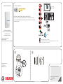
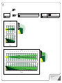
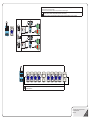
ISC-PDL1-WAC30G
< 93%
-30°C - +55°C (-22°F - +131°F)
For UL Listed Installations, the temperature range is 0°C - +49°C
(+32°F - +120°F), humidity 93%
Professional Series
TriTech+ Curtain Detectors
with Anti-mask
Installation manual
12
12
Optional mounting brackets:
B328, B335, B338
Optional mounting brackets not tested by UL.
2.1 m - 3 m
(7 ft - 10 ft)
ISC-PDL1-WAC30G:
10.500 GHz - 10.525 GHz
<50mW (peak)
Use only a Listed Class 2 Power Limted Source.
For UL Listed product installations, the Listed control unit
or a Listed burglary power supply must provide four hours of
standby power.

© Bosch Security Systems B.V.
F01U287084-06
2023.01 2
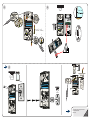
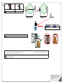
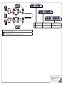
4
3
B328
B335
0.2 mm2 - 1 mm2
(26 AWG - 16 AWG)
1
1
2
2
4
2.1m - 3m

© Bosch Security Systems B.V.
F01U287084-06
2023.01 3
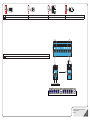
Spare terminals
Bornes libres
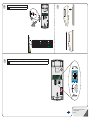
6
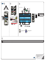
4 5
ISC-PDL1-WAC30G
7
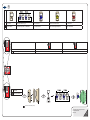
DIP switch settings and voltage from the control panel to the terminal determines the state of the feature (Remote Walk Test and Alarm Memory) associated with that terminal.
La conguration du commutateur DIP et la tension appliquée depuis la centrale à la borne déterminent l’état de la fonction (Test de la détection à distance et Mémoire d’alarme) associée à cette borne.
< 18 mA @ 12 VDC < 26 mA @ 12 VDC

© Bosch Security Systems B.V.
F01U287084-06
2023.01 4
The Alarm Memory function is used when more than one detector is connected to an alarm loop. The Alarm Memory identies the units experiencing an alarm in the last armed period. The detector stores the
alarm event in memory during the armed period. It shows the stored alarm when the system is disarmed. The LED ashes to indicate the stored alarm. Alarm Memory clears when the system is re-armed.
La fonction Mémoire d’alarme est utilisée lorsque plusieurs détecteurs sont connectés à un circuit d’alarme. La mémoire d’alarme identie les appareils dont l’alarme s’est déclenchée lors de la dernière période où le système était
armé. Le détecteur stocke chaque événement d’alarme en mémoire durant la période où le système est armé. Il ache l’alarme mémorisée une fois le système désarmé. Le voyant LED clignote pour indiquer qu’une alarme est
mémorisée. La mémoire d’alarme se vide lorsque le système est ré-armé.
7
Remote Walk Test (WT)
Test de marche à distance (TM)
Alarm Memory polarity (S/U)
Mémoire d’alarme (S/U)

© Bosch Security Systems B.V.
F01U287084-06
2023.01 5
8
Short range (8 m,
25 ft)
Courte portée
Long range (30 m, 100 ft)
Longue portée
3
3
0 2 4 6 8 10
0 7 13 20 26 33
0
2
0
2
0
7
0
7
12
39
14
46
≥2 ≥7
≤3 ≤10
16 30
52 100
Feet
Feet
Meters
Meters
18
59
20
66
22
72
24
79
26
85
28
92
5°
02468
0 7 13 20 25
0
2
0
2
0
7
0
7
≥2 ≥7
≤3 ≤10
Feet
Feet
Meters
Meters
Microwave Passive infrared (PIR)
Hyperfréquence Infrarouge passif (IRP)

© Bosch Security Systems B.V.
F01U287084-06
2023.01 6
To clear an Antimask condition:
1) From the control panel, put the detector into Walk Test Mode. 2) Remove the object that is masking the detector.
3) Perform a Walk Test. The Antimask condition clears.
Pour eacer une condition d’anti-masque :
1) A partir de la centrale, placez le détecteur en mode Test de la détection. 2) Retirez l’objet qui masque le détecteur. 3) Lancez un test de la détection. La condition
d’anti-masque est alors eacée.
9
Antimask off Antimask on
Anti-masque inactif Anti-masque actif
Placement if Antimask feature is enabled
Emplacement si la fonction anti-masque est activée

© Bosch Security Systems B.V.
F01U287084-06
2023.01 7
10 Optional look-down zone
Zone optionnelle de détection vers le bas. 11
If necessary, adjust microwave range slightly until required coverage is met.
Au besoin, ajuster légèrement la portée hyperfréquence jusqu’à atteindre le champ de détection souhaité.
12

© Bosch Security Systems B.V.
F01U287084-06
2023.01 8
Local Walk Test LED enable Walk Test LED on Walk Test LED off
Activation du voyant LED du test de la détection local Voyant LED du test de la détection actif Voyant LED du test de la détection inactif
Perform walk test yearly.
Walk test
Test de la détection
No activity Blue ash: Warming up Blue: Dual alarm Yellow: Microwave alarm Red: PIR alarm
Aucune activité Voyant bleu clignotant : Stabilisation Bleu : Double alarme Jaune : Alarme hyperfréquence Rouge : Alarme IRP
12

© Bosch Security Systems B.V.
F01U287084-06
2023.01 9
Remote Self-Test: Remote Self-test automatically occurs when walk test changes from disabled to en-
abled (change in terminal voltage).
Important! A passing Remote Self-test responds with an alarm signal.
Test automatique à distance : le test automatique à distance est automatiquement activé lorsque le test de la
détection passe de inactif à actif (variation de tension sur la borne).
Important ! Lorsque le test automatique à distance réussit, un signal d’alarme continu est généré.
Self-tests every 8 h. Self-test and remote self-test failure: 4 blue ashes
Test automatique toutes les 8 heures. Echec du test automatique et du test automatique à distance : 4
clignotements bleus

© Bosch Security Systems B.V.
F01U287084-06
2023.01 10
Trouble Memory: Pulse WT input to recall last trouble condition from memory. Pulse WT input again to clear memory. When
memory is recalled, it automatically clears after 12 h.
Mémoire de défaut : Envoyer une impulsion de tension sur WT pour rappeler le dernier défaut mémorisé. Envoyer une impulsion de
tension, à nouveau, pour eacer la
mémoire. Lorsque la mémoire est rappelée, elle s’eace automatiquement au bout de 12 h.
Anti-mask: 3 blue ashes Self-test: 4 blue ashes Low input power: 5 blue ashes
Anti-masque : 3 clignotements
bleus
Test automatique : 4 clignotements bleus Tension d’alimentation basse :
5 clignotements bleus

© Bosch Security Systems B.V.
F01U287084-06
2023.01 11
Local/remote Walk Test LED Alarm Memory polarity (S/U) Long range, short range selection Anti-mask on, o (AM)
Voyant LED du test de la détection local/à distance Polarité dénie/non dénie (D/ND) Sélection longue portée, courte portée Anti-masque actif, inactif (AM)
Low power supervision activates when voltage falls in the range of 6.5 V to 8 V.
La surveillance de la tension d’alimentation basse est activée lorsque la tension est comprise entre 6,5 V et 8V.

© Bosch Security Systems B.V.
F01U287084-06
2023.01
12
Wall tamper System set System unset Walk Test LED enabled Walk Test LED disabled Short Range Coverage
Pattern
Long Range Coverage
Pattern Anti-mask
Autosurveillance à
l’ouverture, à l’arrachement,
à la réorientation et au
champ magnétique
Système activé Système désactivé Voyant LED du test de la
détection activé
Voyant LED du test de la
détection désactivé
Champ de détection courte
portée
Champ de détection
longue portée Anti-masque
FCC Compliance Statement
This equipment has been tested and found to comply with the limits for a Class B digital device, pursuant to part 15 of the FCC Rules. These limits are designed to provide reasonable
protection against harmful interference in a residential installation. This equipment generates, uses and can radiate radio frequency energy and, if not installed and used in accordance with
the instructions, may cause harmful interference to radio communications. However, there is no guarantee that interference will not occur in a particular installation. If this equipment does
cause harmful interference to radio or television reception, which can be determined by turning the equipment off and on, the user is encouraged to try to correct the interference by one or
more of the following measures:
· Reorient or relocate the receiving antenna.
· Increase the separation between the equipment and receiver.
· Connect the equipment into an outlet on a circuit different from that to which the receiver is connected.
· Consult the dealer or an experienced radio/TV technician for help.
This device complies with Part 15 of the FCC Rules. Operation is subject to the following two conditions:
(1) this device may not cause harmful interference, and
(2) this device must accept any interference received, including interference that may cause undesired operation. Please note that changes or modications not expressly approved by
the party responsible for compliance could void the user’s authority to operate the equipment.
Changes or modications not expressly approved by the party responsible for compliance could void the user’s authority to operate the equipment.
FCC RF Exposure Statement
This equipment complies with FCC radiation exposure limits set forth for an uncontrolled environment. This transmitter must not be co-located or operating in conjunction with any other
antenna or transmitter. In order to avoid the possibility of exceeding the FCC radio frequency exposure limits, this equipment should be installed and operated with minimum distance 20 cm
(7.9 inches) between the antenna and your body during normal operation. Users must follow the specic operating instructions for satisfying RF exposure compliance.
-
 1
1
-
 2
2
-
 3
3
-
 4
4
-
 5
5
-
 6
6
-
 7
7
-
 8
8
-
 9
9
-
 10
10
-
 11
11
-
 12
12


Bosch ISC-PDL1-WAC30G Manuel utilisateur
- Taper
- Manuel utilisateur
dans d''autres langues
- English: Bosch ISC-PDL1-WAC30G User manual
Documents connexes
Autres documents
-
Ksenia UNUM User And Installer Manual
-
CAME PROXINET Guide d'installation
-
-
Aritech DDV1016-N Manuel utilisateur
-
Interlogix 50’ Antimasking High Security Sensor Mirror Optic PIR Guide d'installation
-
-
 Digital Monitoring Products Optex CDX Series Installation & Programming Guides
-
Risco RK350DT Installation Instructions Manual
-
Ris Ind. LuNAR 200DTG3 Manuel utilisateur
-
Risco Industrial LuNAR RK200DTG3 Guide d'installation
