Lincoln Electric Flux Core 90i 120V Welder Le manuel du propriétaire
- Catégorie
- Système de soudage
- Taper
- Le manuel du propriétaire
Ce manuel convient également à

Operator’s Manual
IMT10639 | *TTVF D ate +VO - 22
© Lincoln Global, Inc. All Rights Reserved.
For use with Product Numbers:
13397
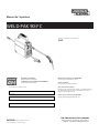
WELD-PAK 90i FC
Register your machine:
www.lincolnelectric.com/register
Authorized Service and Distributor Locator:
www.lincolnelectric.com/locator
Save for future reference
Date Purchased
Code: (ex: 10859)
Serial: (ex: U1060512345)
Need Help? Call 1.888.935.3877
to talk to a Service Representative
Hours of Operation:
8:00 AM to 6:00 PM (ET) Mon. thru Fri.
After hours?
Use “Ask the Experts” at lincolnelectric.com
A Lincoln Service Representative will contact you
no later than the following business day.
For Service outside the USA:
Email: [email protected]

THANK YOU FOR SELECTING
A QUALITY PRODUCT BY
LINCOLN ELEC TRIC.
PLEASE EXAMINE CARTON AND EQUIPMENT FOR
DAMAGE IMMEDIATELY
When this equipment is shipped, title passes to the purchaser
upon receipt by the carrier. Consequently, claims for material
damaged in shipment must be made by the purchaser against the
transportation company at the time the shipment is received.
SAFETY DEPENDS ON YOU
Lincoln arc welding and cutting equipment is designed and built
with safety in mind. However, your overall safety can be increased
by proper installation ... and thoughtful operation on your part.
DO NOT INSTALL, OPERATE OR REPAIR THIS EQUIPMENT
WITHOUT READING THIS MANUAL AND THE SAFETY
PRECAUTIONS CONTAINED THROUGHOUT. And, most importantly,
think before you act and be careful.
This statement appears where the information must be followed
exactly to avoid serious personal injury or loss of life.
This statement appears where the information must be followed
to avoid minor personal injury or damage to this equipment.
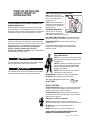
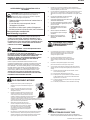
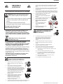
KEEP YOUR HEAD OUT OF THE FUMES.
DON’T get too close to the arc.
Use corrective lenses if necessary
to stay a reasonable distance
away from the arc.
READ and obey the Safety Data
Sheet (SDS) and the warning label
that appears on all containers of
welding materials.
USE ENOUGH VENTILATION or
exhaust at the arc, or both, to
keep the fumes and gases from
your breathing zone and the general area.
IN A LARGE ROOM OR OUTDOORS, natural ventilation may be
adequate if you keep your head out of the fumes (See below).
USE NATURAL DRAFTS or fans to keep the fumes away
from your face.
If you de velop unusual symptoms, see your supervisor.
Perhaps the welding atmosphere and ventilation system
should be checked.
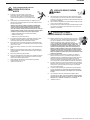
WEAR CORRECT EYE, EAR &
BODY PROTECTION
PROTECT your eyes and face with welding helmet
properly fitted and with proper grade of filter plate
(See ANSI Z49.1).
PROTECT your body from welding spatter and arc
flash with protective clothing including woolen
clothing, flame-proof apron and gloves, leather
leggings, and high boots.
PROTECT others from splatter, flash, and glare
with protective screens or barriers.
IN SOME AREAS, protection from noise may be appropriate.
BE SURE protective equipment is in good condition.
Also, wear safety glasses in work area
AT ALL TIMES.
SPECIAL SITUATIONS
DO NOT WELD OR CUT containers or materials which previously
had been in contact with hazardous substances unless they are
properly cleaned. This is extremely dangerous.
DO NOT WELD OR CUT painted or plated parts unless special
precautions with ventilation have been taken. They can release
highly toxic fumes or gases.
Additional precautionary measures
PROTECT compressed gas cylinders from excessive heat,
mechanical shocks, and arcs; fasten cylinders so they cannot fall.
BE SURE cylinders are never grounded or part of an
electrical circuit.
REMOVE all potential fire hazards from welding area.
ALWAYS HAVE FIRE FIGHTING EQUIPMENT READY FOR
IMMEDIATE USE AND KNOW HOW TO USE IT.
WARNING
CAUTION
6DIHW\RI

SECTION A:
WARNINGS
CALIFORNIA PROPOSITION 65 WARNINGS
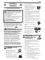
WARNING: Breathing diesel engine exhaust
exposes you to chemicals known to the State
of California to cause cancer and birth defects,
or other reproductive harm.
• Always start and operate the engine in a
well-ventilated area.
• If in an exposed area, vent the exhaust to the outside.
• Do not modify or tamper with the exhaust system.
• Do not idle the engine except as necessary.
For more information go to
www.P65 warnings.ca.gov/diesel
WARNING: This product, when used for welding or
cutting, produces fumes or gases which contain
chemicals known to the State of California to cause
birth defects and, in some cases, cancer. (California
Health & Safety Code § 25249.5 et seq.)
WARNING: Cancer and Reproductive Harm
www.P65warnings.ca.gov
ARC WELDING CAN BE HAZARDOUS. PROTECT
YOURSELF AND OTHERS FROM POSSIBLE SERIOUS
INJURY OR DEATH. KEEP CHILDREN AWAY.
PACEMAKER WEARERS SHOULD CONSULT WITH
THEIR DOCTOR BEFORE OPERATING.
Read and understand the following safety highlights. For
additional safety information, it is strongly recommended
that you purchase a copy of “Safety in Welding & Cutting -
ANSI Standard Z49.1” from the American Welding Society,
P.O. Box 351040, Miami, Florida 33135 or CSA Standard
W117.2. A Free copy of “Arc Welding Safety” booklet E205
is available from the Lincoln Electric Company, 22801
St. Clair Avenue, Cleveland, Ohio 44117-1199.
BE SURE THAT ALL INSTALLATION, OPERATION,
MAINTENANCE AND REPAIR PROCEDURES ARE
PERFORMED ONLY BY QUALIFIED INDIVIDUALS.
FOR ENGINE POWERED
EQUIPMENT.
1.a. Turn the engine off before troubleshooting
and maintenance work unless the
maintenance work requires it to be running.
1.b. Operate engines in open, well-ventilated areas or vent the engine
exhaust fumes outdoors.
arc or when the engine is running. Stop the
engine and allow it to cool before refueling to
prevent spilled fuel from vaporizing on contact
tank. If fuel is spilled, wipe it up and do not start engine until
fumes have been eliminated.
1.d. Keep all equipment safety guards, covers
and devices in position and in good repair.
Keep hands, hair, clothing and tools away
from V-belts, gears, fans and all other
moving parts when starting, operating or
repairing equipment.
1.e. In some cases it may be necessary to remove safety guards to
perform required maintenance. Remove guards only when
necessary and replace them when the maintenance requiring
their removal is complete. Always use the greatest care when
working near moving parts.
1.f. Do not put your hands near the engine fan. Do not attempt to
override the governor or idler by pushing on the throttle control
rods while the engine is running.
1.g. To prevent accidentally starting gasoline engines while turning
the engine or welding generator during maintenance work,
disconnect the spark plug wires, distributor cap or magneto wire
as appropriate.
1.h. To avoid scalding, do not remove the radiator
pressure cap when the engine is hot.
ELECTRIC AND
MAGNETIC FIELDS MAY
BE DANGEROUS
causes localized Electric and Magnetic Fields (EMF).
and welding machines
welders having a pacemaker should consult their physician
before welding.
which are now not known.
2.d. All welders should use the following procedures in order to
2.d.1. Route the electrode and work cables together - Secure
them with tape when possible.
2.d.2. Never coil the electrode lead around your body.
2.d.3. Do not place your body between the electrode and work
cables. If the electrode cable is on your right side, the
work cable should also be on your right side.
2.d.4. Connect the work cable to the workpiece as close as pos-
sible to the area being welded.
2.d.5. Do not work next to welding power source.
SAFETY
Safety 02 of 04 - 10/08/2021
1.c. Do not add the fuel near an open ame welding
with hot engine parts and igniting. Do not spill fuel when lling
2.a. Electric current owing through any conductor
Welding current creates EMF elds around welding cables
2.b. EMF elds may interfere with some pacemakers, and
2.c. Exposure to EMF elds in welding may have other health effects
minimize exposure to EMF elds from the welding circuit:
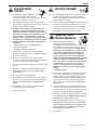
1.i. Using a generator indoors CAN KILL YOU IN
MINUTES.
1.j. Generator exhaust contains carbon monoxide. This is a poison
you cannot see or smell.
1.k. NEVER use inside a home or garage,
EVEN IF doors and windows are open.
1.l. Only use OUTSIDE and far away from
windows, doors and vents.
1.m. Avoid other generator hazards. READ
MANUAL BEFORE USE.

ELECTRIC SHOCK
CAN KILL.
3.a. The electrode and work (or ground) circuits are
electrically “hot” when the welder is on. Do
not touch these “hot” parts with your bare skin or wet clothing.
Wear dry, hole-free gloves to insulate hands.
3.b. Insulate yourself from work and ground using dry insulation.
Make certain the insulation is large enough to cover your full area
of physical contact with work and ground.
In addition to the normal safety precautions, if
welding must be performed under electrically
hazardous conditions (in damp locations or while
wearing wet clothing; on metal structures such as
floors, gratings or scaffolds; when in cramped
positions such as sitting, kneeling or lying, if there
is a high risk of unavoidable or accidental contact
with the workpiece or ground) use the following
equipment:
• Semiautomatic DC Constant Voltage (Wire) Welder.
• DC Manual (Stick) Welder.
• AC Welder with Reduced Voltage Control.
3.c. In semiautomatic or automatic wire welding, the electrode,
electrode reel, welding head, nozzle or semiautomatic welding
gun are also electrically “hot”.
3.d. Always be sure the work cable makes a good electrical
connection with the metal being welded. The connection should
be as close as possible to the area being welded.
3.e. Ground the work or metal to be welded to a good electrical (earth)
ground.
3.f. Maintain the electrode holder, work clamp, welding cable and
welding machine in good, safe operating condition. Replace
damaged insulation.
3.g. Never dip the electrode in water for cooling.
3.h. Never simultaneously touch electrically “hot” parts of electrode
holders connected to two welders because voltage
between the
two can be the total of the open circuit voltage of both
welders.
3.i. When working above floor level, use a safety belt to protect
yourself from a fall should you get a shock.
3.j. Also see It ems 6.c. and 8.
ARC RAYS CAN BURN.
4.a. Use a shield with the proper filter and cover plates to protect your
eyes from sparks and the rays of the arc when welding or
observing open arc welding. Headshield and filter lens should
conform to ANSI Z87. I standards.
4.b. Use suitable clothing made from durable flame-resistant material
to protect your skin and that of your helpers from the arc rays.
4.c. Protect other nearby personnel with suitable, non-flammable
screening and/or warn them not to watch the arc nor expose
themselves to the arc rays or to hot spatter or metal.
FUMES AND GASES
CAN BE DANGEROUS.
5.a. Welding may produce fumes and gases
hazardous to health. Avoid breathing these
fumes and gases. When welding, keep your head out of the fume.
Use enough ventilation and/or exhaust at the arc to keep fumes
and gases away from the breathing zone. When welding
hardfacing (see instructions on container or SDS)
or on lead or cadmium plated steel and other
metals or coatings which produce highly toxic
fumes, keep exposure as low as possible and
within applicable OSHA PEL and ACGIH TLV limits
using local exhaust or mechanical ventilation
unless exposure assessments indicate otherwise.
In confined spaces or in some circumstances,
outdoors, a respirator may also be required.
Additional precautions are also required when
welding
on galvanized steel.
5. b. The operation of welding fume control equipment is affected by
various factors including proper use and positioning of the
equipment, maintenance of the equipment and the specific
welding procedure and application involved. Worker exposure
level should be checked upon installation and periodically
thereafter to be certain it is within applicable OSHA PEL and
ACGIH TLV limits.
5.c. Do not weld in locations near chlorinated hydrocarbon vapors
coming from degreasing, cleaning or spraying operations. The
heat and rays of the arc can react with solvent vapors to form
phosgene, a highly toxic gas, and other irritating products.
5.d. Shielding gases used for arc welding can displace air and
cause
injury or death. Always use enough ventilation, especially in
confined areas, to insure breathing air is safe.
5.e. Read and understand the manufacturer’s instructions for this
equipment and the consumables to be used, including the
Safety Data Sheet (SDS) and follow your employer’s safety
practices. SDS forms are available from your welding
distributor or from the manufacturer.
5.f. Also see item 1.b.
SAFETY
6DIHW\RI

WELDING AND CUTTING
SPARKS CAN CAUSE
FIRE OR EXPLOSION.
6.a. Remove fire hazards from the welding area. If
this is not possible, cover them to prevent the welding sparks
from starting a fire. Remember that welding sparks and hot
materials from welding can easily go through small cracks and
openings to adjacent areas. Avoid welding near hydraulic lines.
Have a fire extinguisher readily available.
6.b. Where compressed gases are to be used at the job site, special
precautions should be used to prevent hazardous situations.
Refer to “Safety in Welding and Cutting” (ANSI Standard Z49.1)
and the operating information for the equipment being used.
6.c. When not welding, make certain no part of the electrode circuit is
touching the work or ground. Accidental contact can cause
overheating and create a fire hazard.
6.d. Do not heat, cut or weld tanks, drums or containers until the
proper steps have been taken to insure that such procedures
will not cause flammable or toxic vapors from substances inside.
They can cause an explosion even though they have been
“cleaned”. For information, purchase “Recommended Safe
Practices for the Preparation for Welding and Cutting of
Containers and Piping That Have Held Hazardous Substances”,
AWS F4.1 from the American Welding Society
(see address above).
6.e. Vent hollow castings or containers before heating, cutting or
welding. They may explode.
6.f. Sparks and spatter are thrown from the welding arc. Wear oil free
protective garments such as leather gloves, heavy shirt, cuffless
trousers, high shoes and a cap over your hair. Wear ear plugs
when welding out of position or in confined places. Always wear
safety glasses with side shields when in a welding area.
6.g. Connect the work cable to the work as close to the welding area
as practical. Work cables connected to the building framework or
other locations away from the welding area increase the
possibility of the welding current passing through lifting chains,
crane cables or other alternate circuits. This can create fire
hazards or overheat lifting chains or cables until they fail.
6.h. Also see item 1.c.
6.I. Read and follow NFPA 51B “Standard for Fire Prevention During
Welding, Cutting and Other Hot Work”, available from NFPA, 1
Batterymarch Park, PO box 9101, Quincy, MA 022690-9101.
6.j. Do not use a welding power source for pipe thawing.
CYLINDER MAY EXPLODE IF
DAMAGED.
7.a. Use only compressed gas cylinders containing
the correct shielding gas for the process used
and properly operating regulators designed for
the gas and pressure used. All hoses, fittings,
etc. should be suitable for the application and
maintained in good condition.
7.b. Always keep cylinders in an upright position securely chained to
an undercarriage or fixed support.
7.c. Cylinders should be located:
• Away from areas where they may be struck or subjected
to physical damage.
• A safe distance from arc welding or cutting operations
and any other source of heat, sparks, or flame.
7.d. Never allow the electrode, electrode holder or any other
electrically “hot” parts to touch a cylinder.
7.e. Keep your head and face away from the cylinder valve outlet
when opening the cylinder valve.
7.f. Valve protection caps should always be in place and hand tight
except when the cylinder is in use or connected for use.
7.g. Read and follow the instructions on compressed gas cylinders,
associated equipment, and CGA publication P-l, “Precautions for
Safe Handling of Compressed Gases in Cylinders,” available from
the Compressed Gas Association, 14501 George Carter Way
Chantilly, VA 20151.
FOR ELECTRICALLY
POWERED EQUIPMENT.
8.a. Turn off input power using the disconnect
switch at the fuse box before working on
the equipment.
8.b. Install equipment in accordance with the U.S. National Electrical
Code, all local codes and the manufacturer’s recommendations.
8.c. Ground the equipment in accordance with the U.S. National
Electrical Code and the manufacturer’s recommendations.
Refer to
http://www.lincolnelectric.com/safety
for additional safety information.
SAFETY
6DIHW\RI

2
WELD-PAK 90i FC
TABLE OF CONTENTS
Installation ................................................................................................................................................................
Technical Specifications................................................................................................................................................
Premium Features.........................................................................................................................................................
Select Suitable Location................................................................................................................................................
Grinding ................................................................................................................................................................
Stacking ................................................................................................................................................................
Transport – Unloading ..................................................................................................................................................
Tilting ................................................................................................................................................................
Environmental Rating .................................................................................................................................................
..
Input Connections .....................................................................................................................................................
...
Wire Loading And Threading.........................................................................................................................................
Operation ................................................................................................................................................................
Operating Machine .....................................................................................................................................................
Replacement Parts Lists..............................................................................................................................................
Maintenance.............................................................................................................................................................1
Routine And Periodic Maintenance ....................................................................................................................
.........1
Troubleshooting........................................................................................................................................................1
How To Use Troubleshooting Guide.............................................................................................................................1
1SPEVDU%FTDSJQUJPO ................................................................................................................................................... 3

INSTALLATIONWELD-PAK 90i FC
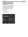
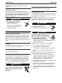
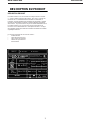
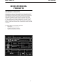
130%6$5%&4$3*15*0/
130%6$546.."3:
5IF8FME1BL¥J'$JTBDPOTUBOUWPMUBHF%$XFMEJOHNBDIJOF
SBUFEGPSBNQTWPMUTBUBEVUZDZDMF5IF8FME1BL¥
VOJUJTJOUFOEFEGPSGBCSJDBUJPONBJOUFOBODFIPNFBOEBVUPCPEZ
TIPQT5IFVOJUGFBUVSFTBQPSUBCMFBOESVHHFEDBTF5IFVTFS
JOUFSGBDFGFBUVSFTUXPLOPCTPOFGPSWPMUBHFBOEPOFGPSXJSFGFFE
TQFFE5IF8FME1BL¥J'$JTEFTJHOFEGPSUIF/PSUI"NFSJDBO
NBSLFUBOEPQFSBUFTPO7TJOHMFQIBTF)[QPXFS"O
PWFSWJFXPGUIFNBDIJOFTJOQVUBOEPVUQVUDBQBCJMJUJFTBSFMJTUFE
POUIFSBUJOHQMBUFTIPXOIFSF
5IFNBDIJOFDPNFTXJUIUIFGPMMPXJOHBDDFTTPSJFT
v 81-HVO
v 8PSLDBCMFXJUIDMBNQ
v 4QBSFDPOUBDUUJQT
v 1SPDFEVSF$IBSUBOEMJUFSBUVSF

INSTALLATIONWELD-PAK 90i FC
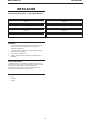
INSTALLATION
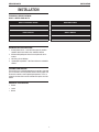
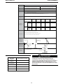
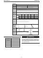
TECHNICAL SPECIFICATIONS -
K5255-1 WELD-PAK 90i FC
PREMIUM FEATURES INCLUDE:
1. Inverter power source – more efcient to operate, provides
smoother weld characteristics than traditional welders
2. Innite welding voltage to allow ne tuning of weld charac-
teristics
3. 30% Duty cycle at 90 Amps
4. Lightweight and portable – Ideal for maintenance and mobile
welders
THERMAL PROTECTION
The machine has a maximum output duty cycle of 30%. If the duty
cycle is exceeded, a thermal protector will shut off the output until
the machine cools to a normal operating temperature. This is an
automatic function of the machine and does not require user inter-
vention.
REQUIRED ACCESSORIES
• Helmet
• Jacket
• Gloves
OUTPUT CURRENT RANGE
30-12A
OPEN CIRCUIT VOLTAGE
V (RMS)
INPUT CIRCUIT
120VAC
DUTY CYCLE
30%@90A
WIREFEED SPEED
0 - 200 IPM
SUITABLE WIRE DIAMETER
0.030”, 0.035”
GROSS WEIGHT
15 LBS (7KGS)
IPS RATING
IP21S

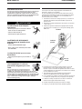
INSTALLATIONWELD-PAK 90i FC
Read this entire installation section before you start
installation.
Safety Precautions
Do not attempt to use this equipment until you have
thoroughly read all installation, operating and maintenance
information supplied with your equipment. They include
important safety precautions and detailed operating and
maintenance instructions.
ELECTRIC SHOCK can kill.
• Only qualied personnel should
perform this installation.
• Do not touch electrically live parts.
• Always connect the machine to an
earthed mains supply.
SELECT SUITABLE LOCATION
Place the welder where clean cooling air can freely circulate in
and out of the front & rear louver vents. Dirt, dust or any foreign
material that can be drawn through vents into welder must be
kept to a minimum. Failure to observe these precautions can
result in excessive operating temperatures which can lead to plant
failure.
GRINDING
Do not direct grinding particles towards the welder. An abundance
of conductive material can cause plant failure.
STACKING
This machine cannot be stacked.
TRANSPORT - UNLOADING
Never underestimate the weight of equipment, never move or
leave suspended in the air above people. The machine should
be lifted and carried by the provided strap, or by cradling the
machine. The machine should not be carried by the input, cord,
output cables, or welding gun. Utilize proper lifting techniques
when carrying or lifting the machine to prevent injury.
Falling Equipment can cause
injury. Never lift welder with gas
bottle attached. Never lift above
personnel.
TILTING
Machine must be placed on a secure level surface
ENVIRONMENTAL RATING
The welding power source carries the IP21S rating. It may be used
in normal industrial and commercial environments. Avoid using in
areas where water / rain is around.
Read and follow the ‘Electric Shock Warnings’ in the safety section
if welding must be performed under electrically hazardous
conditions such as welding in wet areas or water on the work
piece.
ELECTRIC SHOCK can kill.
• This welder must be grounded to earth
The high frequency generator being
similar to a radio transmitter may
cause interference to radio, TV and
other electronic equipment.
• These problems may be the result of
radiated interference. Proper grounding methods can
reduce or eliminate this.
Radiated interference can develop in the following ways
1. Direct interference from welder power source
2. Direct interference from the welding leads
3. Direct interference radiated from feedback into power lines
4. Interference from re-radiation by un-grounded metallic
objects
Keeping these contributing factors in mind, installing equipment
as per following instructions should minimize problems
1. Keep the welder input power lines as short as possible and
enclose as much of them as possible in metal conduit or
equivalent shielding. There should be a good electrical
contact between this conduit and ground (Earth)
2. Keep the work and electrode leads as short as possible. Tape
the leads together where practical
3. Be sure the torch and earth leads rubber coverings are free
from cuts and cracks that allow welding power leakage
4. Keep earth lead connection to work in good condition – Clean
area on workbench where earth clamp is situated on a
regular basis.
WARNING
WARNING
WARNING
CAUTION

INSTALLATIONWELD-PAK 90i FC
INPUT POWER CONNECTION
The machine has one input connection, the power input cable. The
power input cable is located on the rear.
The Weld-Pak 90i FC is provided with a 120V cable, 6.0ft. (1.8m)
in length, with a 15Amp 5-15P plug molded onto the cord.
The rated output of the Weld-Pak 90i FC is available when
connected to a 20A branch circuit. When connected to a branch
circuit with lower capacity, lower welding current and duty cycle
must be used.
CODE REQUIREMENTS FOR ELECTRICAL INPUT
CONNECTIONS
This welding machine must be connected to a power source
in accordance with applicable electrical codes.
The National Electrical Code provides standards for amperage
handling capability of supply conductors based on duty cycle of
the welding source.
If there is any question about the installation meeting applicable
electrical code requirements, consult a qualied electrician.
Do not connect the machine to an input power supply with a
rated voltage that is greater than 125 volts.
Do not remove the power cord ground prong.
EXTENSION CORD USAGE
If an extension cord is required, use one that is rated for the
application and is 3 conductor #14 AWG (2.1 mm2) or larger. The
recommended maximum lengths are 25 ft (7.5 m) if #14 AWG (2.1
mm2) is used and 50 ft (15 m) if #12 AWG (3.3 mm2) is used.
FLUX-CORED (INNERSHIELD) WELDING
The recommended electrode for the ux-cored, self-shielded
process is 0.035” (0.9 mm) diameter Lincoln Innershield
NR-211-MP on 1 lbs. (.5 kg) spools.
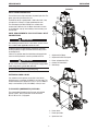
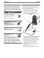
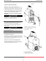
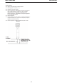
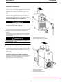
FIGURE 1
1. Adjustment for Voltage
2. Adjustment for Wire feed speed
3. Power and protection LEDs
4. Gasless Flux-Cored torch
5. Work Clamp
6. Power Switch
7. Power Input Cable
8. Spool cover latch
WARNING
WARNING
1
2
3
4
5
6
7
8

INSTALLATIONWELD-PAK 90i FC
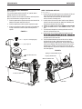
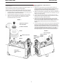
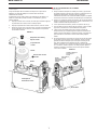
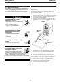
WIRE LOADING AND THREADING
R e fer to F igure 2.
Turn machine power switch to the OFF (“0”) position before
working inside the wire feed enclosure.
Make sure that the wire feed drive roll and the contact tip of the
gun match the diameter and type of wire used.
1. Push the spool onto the spindle so that the wire feeds off the
bottom of the spool, toward the drive roll.
2. Push the spool spacer onto the spindle, against the spool.
3. Slide the spring onto the spool, then press on the spool lock,
turning it clockwise to lock the spool assembly onto the
spindle.
FIGURE 2
WIRE THREADING DETAILS
R efer to F igure 3.
4. Release the spring loaded thumb screw and rotate the idle roll
arm away from the wire feed drive roll. Ensure that the
visible, stenciled size on the drive roll side facing you
matches the wire size being used.
5. Carefully detach the end of the wire from the spool. Maintain
tension on the wire to prevent the spool from unwinding and
do not release the wire until after step 5.
mm).
7. Thread the wire through the incoming guide tube, over the
drive roll, and into the gun liner.
8. Close the idle roll arm and turn down the thumbscrew until
release the welding wire). Make sure the wire is positioned in
the groove of the lower drive roll.
9. The spring loaded thumbscrew on the idle roll arm adjusts
the pressure on the wire. Adjust pressure by turning the
thumbscrew to prevent spool overrun, but still allow smooth
and easy wire feeding. Start with the pressure set to an inter-
mediate value. Readjust, if necessary. If the drive roll slips
while feeding wire, the pressure should be increased until the
wire feeds properly.
FIGURE 3
Spool Lock & Spring Cap
Spool Spacer
Spool
Note Wire Direction
Spindle
!
Spring Loaded Thumb Screw
Ingoing Guide Tube
Wire Feed Drive Roll
Idle Arm
Cold Feed Switch

INSTALLATIONWELD-PAK 90i FC
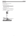
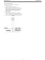
WIRE STICKOUT
10. Remove the contact tip and nozzle from the gun.
11. Turn the machine ON (“I”).
12. Straighten the gun cable assembly.
13. Depress the cold feed switch and feed welding wire through
the gun and cable. (Point the gun away from yourself and
others while feeding wire). Release the cold feed switch after
wire appears at the end of the gun.
14. Turn off the machine.
15. Replace the nozzle and contact tip. Refer to Figure B-4. Cut
the wire off so that 3/8” to 5/8” (10 - 15 mm) protrudes from
the end of the tip.
16. Turn on the machine. The machine is now ready to weld.
FIGURE 4
CONTACT
TIP
WIRE
ELECTRODE
3/8" to 5/8" Contact Tip
To Work Distance
(CTWD)

OPERATION
OPERATION
Read and understand this entire section before operating
your CrossLinc Remote.
WELD-PAK 90i FC
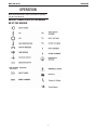
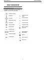
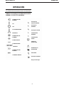
GRAPHIC SYMBOLS USED IN THIS MANUAL
OR BY THIS MACHINE

OPERATION
snoituacerP ytefaS
Do not attempt to use this equipment until you have
thoroughly read all operating and maintenance manuals
supplied with your equipment and any related welding
machine it will be used with. They include important safety
precautions, operating and maintenance instructions and
parts lists.
ELECTRIC SHOCK can kill.
• Do not touch electrically live parts such as
output terminals or internal wiring.
• Insulate yourself from the work and
ground.
• Always wear dry insulating gloves.
or explosion.
• Do not weld upon containers which have
held combustibles.
ARC RAYS can burn.
• Wear eye, ear and body protection.
FUMES AND GASES can
be dangerous.
Although the removal of the particulate
matter from welding smoke may reduce
the ventilation requirement, concentrations
of the clear exhausted fumes and gases may still be
hazardous to health. Avoid breathing concentrations of
these fumes and gases. Use adequate ventilation when
welding. See ANSI Z49.1, "Safety in Welding and Cutting",
published by the American Welding Society.
OPERATING MACHINE
Once you have set machine up as per instructions, refer to Table
B.1 and the Procedure Decal located on the inside of the wire
drive compartment door of your machine for setup information,
consumables, and quick tips for welding.
1. Select welding voltage (power), based on the material
thickness of the work piece, required on front panel
2. Select wire feed speed required on ‘wire speed’ knob
3. Ensure you are wearing the correct safety clothes &
equipment for welding (I.E Welding mask, gloves, apron etc)
FIGURE 5
4. Connect the work clamp to the metal to be welded. The work
clamp must make good electrical contact to the work piece.
The work piece must also be grounded as stated in Arc
Welding Safety Precautions in the beginning of this manual.
5. Based on the weld joint type and orientation of the weld joint,
position the gun into the joint at the correct angle.
6. To begin welding, raise your hand shield or lower your
helmet to protect your eyes and pull the trigger.
7. While welding, travel at a constant speed and maintain an
electrode stickout of 3/8".
8. To stop welding, release the gun trigger.
9. When no more welding is to be done, turn off the machine.
WARNING
Gun Cable
Workpiece
Work Clamp
WELD-PAK 90i FC

OPERATION
TABLE B.1
REPLACE PARTS LIST
Use of this unit on thicker materials than recommended may
result in welds of poor quality. The welds may appear to be
strong weld. This is called "Cold Casting" or "cold lapping"
and is some what similar to a cold solder joint. Weld failure
may result.
Contact Tip (.035”) KH712 (.035” / 0.9MM)
Drive Roll KP4364-035
Nozzle KH726
FCAW Wire LINCOLN .030 NR-211-MP
WARNING
WELD-PAK 90i FC
Welding Wire
Contact Tip
Drive Roll
Horizontal: "Drag"
Tee Joint
Maintain an electrode Stickout
of 3/8" while welding.
Wire Feed
Tension
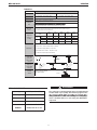
.035 (0.9mm) - Lincoln Part No. KH712
The suggested Wire Feed Speed settings in the table below are based on a midrange wire tension
setting. The tension may be changed if required to improved wire feeding; however, the WFS setting may
have to be adjusted from the values in the table below.
Do NOT weave the arc, neither forward, backward, or sideways
FCAW -Gasless (Flux Cored)
.035 Lincoln NR-211-MP (Innershield Cored Wire)
Loading The
Wire
Suggested
Settings For
Welding
Remember: Remove the contact tip prior to loading wire
Keep tension on the wire to prevent unspooling.
2. Release spring loaded pressure arm and rotate the Idle Roll Arm away from Drive Roll.
3. Thread wire through the guide tube, over drive roll and into gun liner. Close Idle Roll arm.
Weld at a Steady Pace
Helpful Hints
For Horizontal Weld Joints, remember: "Drag if there’s Slag"
Refer to Manual for Troubleshooting Poor Weld Quality
Remove Slag with the Chipping Hammer to expose weld
Proper Gun
Angles for
common Weld
Joint Types
Direction of
Welding AND
Angle of Gun
relative to Weld
Direction
Electrical
Stickout
CONTACT TIP
ELECTRODE 3/8
V
ertical Down
Butt Joint Lap Joint
Vertical Up
45° 45°
.030 Lincoln NR-211-MP (Innershield Cored Wire)
.030 (0.8mm) - Lincoln Part No. KH711
0.030/0.035 (0.8mm/0.9mm) Knurled groove - Lincoln Part No. KP4364-035
20ga
0.9mm
18ga
1.2mm
16ga
1.6mm
14ga
2.1mm
1/8”ga
3.2mm
0.030 NR-
211
Voltage 1.5 2.5 3 4 6
WFS 3.5 5 7 8 10
0.035 NR-
211
Voltage --2346
WFS -- 3 4.5 6 10
NO GAS WITH NR-211
WIRE
Contact Tip (.030”) KH711 (.030” / 0.8MM)
FCAW Wire LINCOLN .035 NR-211-MP

TROUBLESHOOTING
WELD-PAK 90i FC
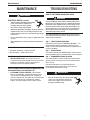
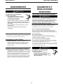
MAINTENANCE
ELECTRIC SHOCK can kill.
• Turn the input power OFF at the welding
power source before installation or
changing drive rolls and/or guides.
• Do not touch electrically live parts.
• When inching with the gun trigger, electrode and drive
mechanism are "hot" to work and ground and could
remain energized several seconds after the gun trigger
is released.
• Do not operate with covers, panels or guards removed
or open.
• Only qualified personnel should perform maintenance
work.
ITEMS REQUIRING NO MAINTENANCE
• Drive Motor and Gearbox – Lifetime lubrication
• Wire Reel Spindle – Do NOT lubricate shaft
ROUTINE AND PERIODIC MAINTENANCE
•BEFORE EACH USE - Check over machine and
accessories for any obvious condition that may prevent safe
performance or operation. Repair or replace items as
necessary to correct any abnormal condition.
AFTER 5 MINUTES OF WELDING OR WHEN SPATTER
ACCUMULATES ON THE CONTACT TIP:
•CLEANING TIP AND NOZZLE - With the power
switch in the off position, keep the contact tip and nozzle
clean to avoid arc bridging between them. Bridging can
result in a shorted nozzle, poor welds and an overheated gun.
Hint: Anti-stick spray or gel, available from a welding
supplier, may reduce buildup and aid in spatter removal.
TROUBLESHOOTING
HOW TO USE TROUBLESHOOTING GUIDE
Service and Repair should only be performed by Lincoln
Electric Factory Trained Personnel. Unauthorized repairs
performed on this equipment may result in danger to the
technician and machine operator and will invalidate your
factory warranty. For your safety and to avoid Electrical
Shock, please observe all safety notes and precautions
detailed throughout this manual.
This Troubleshooting Guide is provided to help you locate and
repair possible machine malfunctions. Simply follow the three-
step procedure listed below.
Step 1. LOCATE PROBLEM (SYMPTOM).
Look under the column labeled “PROBLEM (SYMPTOMS).” This
column describes possible symptoms that the machine may
exhibit. Find the listing that best describes the symptom that the
machine is exhibiting.
Step 2. POSSIBLE CAUSE.
The second column labeled “POSSIBLE CAUSE” lists the obvious
external possibilities that may contribute to the machine symptom.
Step 3. RECOMMENDED COURSE OF ACTION
This column provides a course of action for the Possible Cause,
generally it states to contact you local Lincoln Authorized Field
Service Facility.
If you do not understand or are unable to perform the
Recommended Course of Action safely, contact your local
Lincoln Authorized Field Service Facility.
E
ELECTRIC SHOCK can kill.
• Turn off machine at the disconnect switch
on the rear of the machine and remove
main power supply connections before
doing any troubleshooting.
WARNING
WARNING
WARNING

TROUBLESHOOTING
WELD-PAK 90i FC
Observe all Safety Guidelines detailed throughout this manual
If for any reason you do not understand the test procedures or are unable to perform the tests/repairs safely, contact your
Lincoln Authorized Service Facility for technical troubleshooting assistance before you proceed.
WWW.LINCOLNELECTRIC.COM/LOCATOR
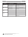
PROBLEM
(SYMPTOMS)
POSSIBLE AREAS OF
MISADJUSTMENT(S) RECOMMENDED COURSE OF ACTION
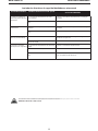
Bead is too thick (inter-
mittently).
Travel speed is slow and/or inconsistent. Increase and maintain a constant travel speed.
Output heat range is too high. Turn the voltage down.
Bead does not penetrate base
metal.
Travel speed is inconsistent. Decrease and maintain a constant travel speed.
Output heat range is too low. Turn the voltage up.
Wire sputters and sticks to
workpiece.
The wire is damp. Change to dry wire. Be sure wire is stored in a dry location
Wire feed speed (WFS) is too fast. Reduce WFS.
Edge of weld has ragged
depressions.
Travel speed is too fast. Reduce travel speed.
WFS is too fast. Reduce WFS.
Output heat range is too high. Set the Low – High Heat Range switch to Low or the Fine
Heat Adjustment to (1).

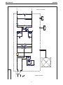
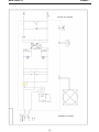
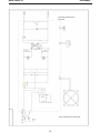
DIAGRAMS
AC1
AC2
G
34
1
3-4
+2
12V
J
2 1
5
6
4
1
3
4
12
7
19 2
1
9
11 10
8
20
OUT +
OUT -
K 1 A C 120V /50/60HZ
RECITIFIER
REAR OF MACHINE
FRONT OF MACHINE
+t
1
2
FAN
1
2
MOTOR
M
1
2
TORCH
3 4
WELD-PAK 90i FC

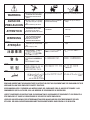
WARNING
AVISO DE
PRECAUCION
ATTENTION
WARNUNG
ATENÇÃO
Spanish
French
German
Portuguese
Japanese
Chinese
Korean
Arabic
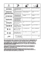
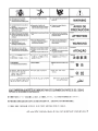
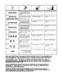
READ AND UNDERSTAND THE MANUFACTURER’S INSTRUCTION FOR THIS EQUIPMENT AND THE CONSUMABLES TO BE
USED AND FOLLOW YOUR EMPLOYER’S SAFETY PRACTICES.
SE RECOMIENDA LEER Y ENTENDER LAS INSTRUCCIONES DEL FABRICANTE PARA EL USO DE ESTE EQUIPO Y LOS
CONSUMIBLES QUE VA A UTILIZAR, SIGA LAS MEDIDAS DE SEGURIDAD DE SU SUPERVISOR.
LISEZ ET COMPRENEZ LES INSTRUCTIONS DU FABRICANT EN CE QUI REGARDE CET EQUIPMENT ET LES PRODUITS A
ETRE EMPLOYES ET SUIVEZ LES PROCEDURES DE SECURITE DE VOTRE EMPLOYEUR.
LESEN SIE UND BEFOLGEN SIE DIE BETRIEBSANLEITUNG DER ANLAGE UND DEN ELEKTRODENEINSATZ DES HER-
STELLERS. DIE UNFALLVERHÜTUNGSVORSCHRIFTEN DES ARBEITGEBERS SIND EBENFALLS ZU BEACHTEN.
Do not touch electrically live parts or
electrode with skin or wet clothing.
Insulate yourself from work and
ground.
No toque las partes o los electrodos
bajo carga con la piel o ropa moja-
da.
Aislese del trabajo y de la tierra.
Ne laissez ni la peau ni des vête-
ments mouillés entrer en contact
avec des pièces sous tension.
Isolez-vous du travail et de la terre.
Berühren Sie keine stromführenden
Teile oder Elektroden mit Ihrem
Körper oder feuchter Kleidung!
Isolieren Sie sich von den
Elektroden und dem Erdboden!
Não toque partes elétricas e elec-
trodos com a pele ou roupa molha-
da.
Isole-se da peça e terra.
Keep flammable materials away.
Mantenga el material combustible
fuera del área de trabajo.
Gardez à l’écart de tout matériel
inflammable.
Entfernen Sie brennbarres Material!
Mantenha inflamáveis bem guarda-
dos.
Wear eye, ear and body protection.
Protéjase los ojos, los oídos y el
cuerpo.
Protégez vos yeux, vos oreilles et
votre corps.
Tragen Sie Augen-, Ohren- und Kör-
perschutz!
Use proteção para a vista, ouvido e
corpo.

WARNING
AVISO DE
PRECAUCION
ATTENTION
WARNUNG
ATENÇÃO
Spanish
French
German
Portuguese
Japanese
Chinese
Korean
Arabic
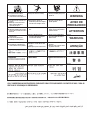
LEIA E COMPREENDA AS INSTRUÇÕES DO FABRICANTE PARA ESTE EQUIPAMENTO E AS PARTES DE USO, E SIGA AS
PRÁTICAS DE SEGURANÇA DO EMPREGADOR.
Keep your head out of fumes.
Use ventilation or exhaust to
remove fumes from breathing zone.
Los humos fuera de la zona de res-
piración.
Mantenga la cabeza fuera de los
humos. Utilice ventilación o
aspiración para gases.
Gardez la tête à l’écart des fumées.
Utilisez un ventilateur ou un aspira-
teur pour ôter les fumées des zones
de travail.
Vermeiden Sie das Einatmen von
Schweibrauch!
Sorgen Sie für gute Be- und
Entlüftung des Arbeitsplatzes!
Mantenha seu rosto da fumaça.
Use ventilação e exhaustão para
remover fumo da zona respiratória.
Turn power off before servicing.
Desconectar el cable de ali-
mentación de poder de la máquina
antes de iniciar cualquier servicio.
Débranchez le courant avant l’entre-
tien.
Strom vor Wartungsarbeiten
abschalten! (Netzstrom völlig öff-
nen; Maschine anhalten!)
Não opere com as tampas removidas.
Desligue a corrente antes de fazer
serviço.
Não toque as partes elétricas nuas.
Do not operate with panel open or
guards off.
No operar con panel abierto o
guardas quitadas.
N’opérez pas avec les panneaux
ouverts ou avec les dispositifs de
protection enlevés.
Anlage nie ohne Schutzgehäuse
oder Innenschutzverkleidung in
Betrieb setzen!
Mantenha-se afastado das partes
moventes.
Não opere com os paineis abertos
ou guardas removidas.
La page charge ...
La page charge ...
La page charge ...
La page charge ...
La page charge ...
La page charge ...
La page charge ...
La page charge ...
La page charge ...
La page charge ...
La page charge ...
La page charge ...
La page charge ...
La page charge ...
La page charge ...
La page charge ...
La page charge ...
La page charge ...
La page charge ...
La page charge ...
La page charge ...
La page charge ...
La page charge ...
La page charge ...
La page charge ...
La page charge ...
La page charge ...
La page charge ...
La page charge ...
La page charge ...
La page charge ...
La page charge ...
La page charge ...
La page charge ...
La page charge ...
La page charge ...
La page charge ...
La page charge ...
La page charge ...
La page charge ...
La page charge ...
La page charge ...
La page charge ...
-
 1
1
-
 2
2
-
 3
3
-
 4
4
-
 5
5
-
 6
6
-
 7
7
-
 8
8
-
 9
9
-
 10
10
-
 11
11
-
 12
12
-
 13
13
-
 14
14
-
 15
15
-
 16
16
-
 17
17
-
 18
18
-
 19
19
-
 20
20
-
 21
21
-
 22
22
-
 23
23
-
 24
24
-
 25
25
-
 26
26
-
 27
27
-
 28
28
-
 29
29
-
 30
30
-
 31
31
-
 32
32
-
 33
33
-
 34
34
-
 35
35
-
 36
36
-
 37
37
-
 38
38
-
 39
39
-
 40
40
-
 41
41
-
 42
42
-
 43
43
-
 44
44
-
 45
45
-
 46
46
-
 47
47
-
 48
48
-
 49
49
-
 50
50
-
 51
51
-
 52
52
-
 53
53
-
 54
54
-
 55
55
-
 56
56
-
 57
57
-
 58
58
-
 59
59
-
 60
60
-
 61
61
-
 62
62
-
 63
63


Lincoln Electric Flux Core 90i 120V Welder Le manuel du propriétaire
- Catégorie
- Système de soudage
- Taper
- Le manuel du propriétaire
- Ce manuel convient également à
dans d''autres langues
Documents connexes
-
Lincoln Electric LN-25 Pro Mode d'emploi
-
Lincoln Electric Red-D-Arc LN-25 Pro Extreme Mode d'emploi
-
Lincoln Electric AutoDrive 4R100 Mode d'emploi
-
-
-
Lincoln Electric POWER MIG 256 Manuel utilisateur
-
-
-
Lincoln Electric IM756-A Manuel utilisateur