Lincoln Electric IM808-A Manuel utilisateur
- Catégorie
- Système de soudage
- Taper
- Manuel utilisateur
Ce manuel convient également à

IEC 60974-1
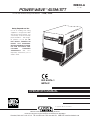
POWER WAVE 455M/STT
™
OPERATOR’S MANUAL
IM808-A
June, 2004
Safety Depends on You
Lincoln arc welding and cutting
equipment is designed and built
with safety in mind. However, your
overall safety can be increased by
proper installation ... and thought-
ful operation on your part. DO
NOT INSTALL, OPERATE OR
REPAIR THIS EQUIPMENT
WITHOUT READING THIS MAN-
UAL AND THE SAFETY PRE-
CAUTIONS CONTAINED
THROUGHOUT. And, most
importantly, think before you act
and be careful.
For use with machines having Code Numbers:
11008, 11204
• Sales and Service through Subsidiaries and Distributors Worldwide •
Cleveland, Ohio 44117-1199 U.S.A. TEL: 216.481.8100 FAX: 216.486.1751 WEB SITE: www.lincolnelectric.com
• World's Leader in Welding and Cutting Products •
Copyright © 2004 Lincoln Global Inc.
NRTL/C

FOR ENGINE
powered equipment.
1.a. Turn the engine off before troubleshooting and maintenance
work unless the maintenance work requires it to be running.
____________________________________________________
1.b. Operate engines in open, well-ventilated
areas or vent the engine exhaust fumes
outdoors.
____________________________________________________
1.c. Do not add the fuel near an open flame weld-
ing arc or when the engine is running. Stop
the engine and allow it to cool before refuel-
ing to prevent spilled fuel from vaporizing on
contact with hot engine parts and igniting. Do
not spill fuel when filling tank. If fuel is spilled,
wipe it up and do not start engine until fumes
have been eliminated.
____________________________________________________
1.d. Keep all equipment safety guards, covers and devices in posi-
tion and in good repair.Keep hands, hair, clothing and tools
away from V-belts, gears, fans and all other moving parts
when starting, operating or repairing equipment.
____________________________________________________
1.e. In some cases it may be necessary to remove safety
guards to perform required maintenance. Remove
guards only when necessary and replace them when the
maintenance requiring their removal is complete.
Always use the greatest care when working near moving
parts.
___________________________________________________
1.f. Do not put your hands near the engine fan.
Do not attempt to override the governor or
idler by pushing on the throttle control rods
while the engine is running.
___________________________________________________
1.g. To prevent accidentally starting gasoline engines while
turning the engine or welding generator during maintenance
work, disconnect the spark plug wires, distributor cap or
magneto wire as appropriate.
i
SAFETY
i
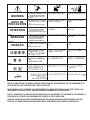
ARC WELDING CAN BE HAZARDOUS. PROTECT YOURSELF AND OTHERS FROM POSSIBLE SERIOUS INJURY OR DEATH.
KEEP CHILDREN AWAY. PACEMAKER WEARERS SHOULD CONSULT WITH THEIR DOCTOR BEFORE OPERATING.
Read and understand the following safety highlights. For additional safety information, it is strongly recommended that you
purchase a copy of “Safety in Welding & Cutting - ANSI Standard Z49.1” from the American Welding Society, P.O. Box 351040,
Miami, Florida 33135 or CSA Standard W117.2-1974. A Free copy of “Arc Welding Safety” booklet E205 is available from the
Lincoln Electric Company, 22801 St. Clair Avenue, Cleveland, Ohio 44117-1199.
BE SURE THAT ALL INSTALLATION, OPERATION, MAINTENANCE AND REPAIR PROCEDURES ARE
PERFORMED ONLY BY QUALIFIED INDIVIDUALS.
WARNING
Mar ‘95
ELECTRIC AND
MAGNETIC FIELDS
may be dangerous
2.a. Electric current flowing through any conductor causes
localized Electric and Magnetic Fields (EMF). Welding
current creates EMF fields around welding cables and
welding machines
2.b. EMF fields may interfere with some pacemakers, and
welders having a pacemaker should consult their physician
before welding.
2.c. Exposure to EMF fields in welding may have other health
effects which are now not known.
2.d. All welders should use the following procedures in order to
minimize exposure to EMF fields from the welding circuit:
2.d.1.
Route the electrode and work cables together - Secure
them with tape when possible.
2.d.2. Never coil the electrode lead around your body.
2.d.3. Do not place your body between the electrode and
work cables. If the electrode cable is on your right
side, the work cable should also be on your right side.
2.d.4. Connect the work cable to the workpiece as close as
possible to the area being welded.
2.d.5. Do not work next to welding power source.
1.h. To avoid scalding, do not remove the
radiator pressure cap when the engine is
hot.
CALIFORNIA PROPOSITION 65 WARNINGS
Diesel engine exhaust and some of its constituents
are known to the State of California to cause can-
cer, birth defects, and other reproductive harm.
The engine exhaust from this product contains
chemicals known to the State of California to cause
cancer, birth defects, or other reproductive harm.
The Above For Diesel Engines
The Above For Gasoline Engines

ii
SAFETY
ii
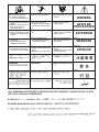
ARC RAYS can burn.
4.a. Use a shield with the proper filter and cover
plates to protect your eyes from sparks and
the rays of the arc when welding or observing
open arc welding. Headshield and filter lens
should conform to ANSI Z87. I standards.
4.b. Use suitable clothing made from durable flame-resistant
material to protect your skin and that of your helpers from
the arc rays.
4.c. Protect other nearby personnel with suitable, non-flammable
screening and/or warn them not to watch the arc nor expose
themselves to the arc rays or to hot spatter or metal.
ELECTRIC SHOCK can kill.
3.a. The electrode and work (or ground) circuits
are electrically “hot” when the welder is on.
Do not touch these “hot” parts with your bare
skin or wet clothing. Wear dry, hole-free
gloves to insulate hands.
3.b. Insulate yourself from work and ground using dry insulation.
Make certain the insulation is large enough to cover your full
area of physical contact with work and ground.
In addition to the normal safety precautions, if welding
must be performed under electrically hazardous
conditions (in damp locations or while wearing wet
clothing; on metal structures such as floors, gratings or
scaffolds; when in cramped positions such as sitting,
kneeling or lying, if there is a high risk of unavoidable or
accidental contact with the workpiece or ground) use
the following equipment:
• Semiautomatic DC Constant Voltage (Wire) Welder.
• DC Manual (Stick) Welder.
• AC Welder with Reduced Voltage Control.
3.c. In semiautomatic or automatic wire welding, the electrode,
electrode reel, welding head, nozzle or semiautomatic
welding gun are also electrically “hot”.
3.d. Always be sure the work cable makes a good electrical
connection with the metal being welded. The connection
should be as close as possible to the area being welded.
3.e. Ground the work or metal to be welded to a good electrical
(earth) ground.
3.f.
Maintain the electrode holder, work clamp, welding cable and
welding machine in good, safe operating condition. Replace
damaged insulation.
3.g. Never dip the electrode in water for cooling.
3.h. Never simultaneously touch electrically “hot” parts of
electrode holders connected to two welders because voltage
between the two can be the total of the open circuit voltage
of both welders.
3.i. When working above floor level, use a safety belt to protect
yourself from a fall should you get a shock.
3.j. Also see Items 6.c. and 8.
FUMES AND GASES
can be dangerous.
5.a. Welding may produce fumes and gases
hazardous to health. Avoid breathing these
fumes and gases.When welding, keep
your head out of the fume. Use enough
ventilation and/or exhaust at the arc to keep
fumes and gases away from the breathing zone. When
welding with electrodes which require special
ventilation such as stainless or hard facing (see
instructions on container or MSDS) or on lead or
cadmium plated steel and other metals or coatings
which produce highly toxic fumes, keep exposure as
low as possible and below Threshold Limit Values (TLV)
using local exhaust or mechanical ventilation. In
confined spaces or in some circumstances, outdoors, a
respirator may be required. Additional precautions are
also required when welding on galvanized steel.
5.b.
Do not weld in locations near chlorinated hydrocarbon
vapors
coming from degreasing, cleaning or spraying operations.
The heat and rays of the arc can react with solvent vapors
to
form phosgene, a highly toxic gas, and other irritating prod-
ucts.
5.c. Shielding gases used for arc welding can displace air and
cause injury or death. Always use enough ventilation,
especially in confined areas, to insure breathing air is safe.
5.d. Read and understand the manufacturer’s instructions for this
equipment and the consumables to be used, including the
material safety data sheet (MSDS) and follow your
employer’s safety practices. MSDS forms are available from
your welding distributor or from the manufacturer.
5.e. Also see item 1.b.
Mar ‘95

FOR ELECTRICALLY
powered equipment.
8.a. Turn off input power using the disconnect
switch at the fuse box before working on
the equipment.
8.b. Install equipment in accordance with the U.S. National
Electrical Code, all local codes and the manufacturer’s
recommendations.
8.c. Ground the equipment in accordance with the U.S. National
Electrical Code and the manufacturer’s recommendations.
CYLINDER may explode
if damaged.
7.a. Use only compressed gas cylinders
containing the correct shielding gas for the
process used and properly operating
regulators designed for the gas and
pressure used. All hoses, fittings, etc. should be suitable for
the application and maintained in good condition.
7.b. Always keep cylinders in an upright position securely
chained to an undercarriage or fixed support.
7.c. Cylinders should be located:
• Away from areas where they may be struck or subjected to
physical damage.
• A safe distance from arc welding or cutting operations and
any other source of heat, sparks, or flame.
7.d. Never allow the electrode, electrode holder or any other
electrically “hot” parts to touch a cylinder.
7.e. Keep your head and face away from the cylinder valve outlet
when opening the cylinder valve.
7.f. Valve protection caps should always be in place and hand
tight except when the cylinder is in use or connected for
use.
7.g. Read and follow the instructions on compressed gas
cylinders, associated equipment, and CGA publication P-l,
“Precautions for Safe Handling of Compressed Gases in
Cylinders,” available from the Compressed Gas Association
1235 Jefferson Davis Highway, Arlington, VA 22202.
iii
SAFETY
iii
Mar ‘95
WELDING SPARKS can
cause fire or explosion.
6.a.
Remove fire hazards from the welding area.
If this is not possible, cover them to prevent
the welding sparks from starting a fire.
Remember that welding sparks and hot
materials from welding can easily go through small cracks
and openings to adjacent areas. Avoid welding near
hydraulic lines. Have a fire extinguisher readily available.
6.b. Where compressed gases are to be used at the job site,
special precautions should be used to prevent hazardous
situations. Refer to “Safety in Welding and Cutting” (ANSI
Standard Z49.1) and the operating information for the
equipment being used.
6.c. When not welding, make certain no part of the electrode
circuit is touching the work or ground. Accidental contact can
cause overheating and create a fire hazard.
6.d. Do not heat, cut or weld tanks, drums or containers until the
proper steps have been taken to insure that such procedures
will not cause flammable or toxic vapors from substances
inside. They can cause an explosion even
though
they have
been “cleaned”. For information, purchase “Recommended
Safe Practices for the
Preparation
for Welding and Cutting of
Containers and Piping That Have Held Hazardous
Substances”, AWS F4.1 from the American Welding Society
(see address above).
6.e. Vent hollow castings or containers before heating, cutting or
welding. They may explode.
6.f.
Sparks and spatter are thrown from the welding arc. Wear oil
free protective garments such as leather gloves, heavy shirt,
cuffless trousers, high shoes and a cap over your hair. Wear
ear plugs when welding out of position or in confined places.
Always wear safety glasses with side shields when in a
welding area.
6.g. Connect the work cable to the work as close to the welding
area as practical. Work cables connected to the building
framework or other locations away from the welding area
increase the possibility of the welding current passing
through lifting chains, crane cables or other alternate circuits.
This can create fire hazards or overheat lifting chains or
cables until they fail.
6.h. Also see item 1.c.

iv
SAFETY
iv
PRÉCAUTIONS DE SÛRETÉ
Pour votre propre protection lire et observer toutes les instructions
et les précautions de sûreté specifiques qui parraissent dans ce
manuel aussi bien que les précautions de sûreté générales suiv-
antes:
Sûreté Pour Soudage A L’Arc
1. Protegez-vous contre la secousse électrique:
a. Les circuits à l’électrode et à la piéce sont sous tension
quand la machine à souder est en marche. Eviter toujours
tout contact entre les parties sous tension et la peau nue
ou les vétements mouillés. Porter des gants secs et sans
trous pour isoler les mains.
b. Faire trés attention de bien s’isoler de la masse quand on
soude dans des endroits humides, ou sur un plancher met-
allique ou des grilles metalliques, principalement dans
les positions assis ou couché pour lesquelles une grande
partie du corps peut être en contact avec la masse.
c. Maintenir le porte-électrode, la pince de masse, le câble de
soudage et la machine à souder en bon et sûr état defonc-
tionnement.
d.Ne jamais plonger le porte-électrode dans l’eau pour le
refroidir.
e. Ne jamais toucher simultanément les parties sous tension
des porte-électrodes connectés à deux machines à souder
parce que la tension entre les deux pinces peut être le total
de la tension à vide des deux machines.
f. Si on utilise la machine à souder comme une source de
courant pour soudage semi-automatique, ces precautions
pour le porte-électrode s’applicuent aussi au pistolet de
soudage.
2. Dans le cas de travail au dessus du niveau du sol, se protéger
contre les chutes dans le cas ou on recoit un choc. Ne jamais
enrouler le câble-électrode autour de n’importe quelle partie du
corps.
3. Un coup d’arc peut être plus sévère qu’un coup de soliel, donc:
a. Utiliser un bon masque avec un verre filtrant approprié ainsi
qu’un verre blanc afin de se protéger les yeux du rayon-
nement de l’arc et des projections quand on soude ou
quand on regarde l’arc.
b. Porter des vêtements convenables afin de protéger la peau
de soudeur et des aides contre le rayonnement de l‘arc.
c. Protéger l’autre personnel travaillant à proximité au
soudage à l’aide d’écrans appropriés et non-inflammables.
4. Des gouttes de laitier en fusion sont émises de l’arc de
soudage. Se protéger avec des vêtements de protection libres
de l’huile, tels que les gants en cuir, chemise épaisse, pan-
talons sans revers, et chaussures montantes.
5. Toujours porter des lunettes de sécurité dans la zone de
soudage. Utiliser des lunettes avec écrans lateraux dans les
zones où l’on pique le laitier.
6. Eloigner les matériaux inflammables ou les recouvrir afin de
prévenir tout risque d’incendie dû aux étincelles.
7. Quand on ne soude pas, poser la pince à une endroit isolé de
la masse. Un court-circuit accidental peut provoquer un
échauffement et un risque d’incendie.
8. S’assurer que la masse est connectée le plus prés possible de
la zone de travail qu’il est pratique de le faire. Si on place la
masse sur la charpente de la construction ou d’autres endroits
éloignés de la zone de travail, on augmente le risque de voir
passer le courant de soudage par les chaines de levage,
câbles de grue, ou autres circuits. Cela peut provoquer des
risques d’incendie ou d’echauffement des chaines et des
câbles jusqu’à ce qu’ils se rompent.
9. Assurer une ventilation suffisante dans la zone de soudage.
Ceci est particuliérement important pour le soudage de tôles
galvanisées plombées, ou cadmiées ou tout autre métal qui
produit des fumeés toxiques.
10. Ne pas souder en présence de vapeurs de chlore provenant
d’opérations de dégraissage, nettoyage ou pistolage. La
chaleur ou les rayons de l’arc peuvent réagir avec les vapeurs
du solvant pour produire du phosgéne (gas fortement toxique)
ou autres produits irritants.
11. Pour obtenir de plus amples renseignements sur la sûreté, voir
le code “Code for safety in welding and cutting” CSA Standard
W 117.2-1974.
PRÉCAUTIONS DE SÛRETÉ POUR
LES MACHINES À SOUDER À
TRANSFORMATEUR ET À
REDRESSEUR
1. Relier à la terre le chassis du poste conformement au code de
l’électricité et aux recommendations du fabricant. Le dispositif
de montage ou la piece à souder doit être branché à une
bonne mise à la terre.
2. Autant que possible, I’installation et l’entretien du poste seront
effectués par un électricien qualifié.
3. Avant de faires des travaux à l’interieur de poste, la debranch-
er à l’interrupteur à la boite de fusibles.
4. Garder tous les couvercles et dispositifs de sûreté à leur place.
Mar. ‘93

v
SAFETY
v

vi
SAFETY
vi

viivii
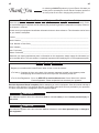
Thank You
for selecting a QUALITY product by Lincoln Electric. We want you
to take pride in operating this Lincoln Electric Company product •••
as much pride as we have in bringing this product to you!
Read this Operators Manual completely before attempting to use this equipment. Save this manual and keep it
handy for quick reference. Pay particular attention to the safety instructions we have provided for your protection.
The level of seriousness to be applied to each is explained below:
WARNING
This statement appears where the information must be followed exactly to avoid serious personal injury or
loss of life.
This statement appears where the information must be followed to avoid minor personal injury or damage to
this equipment.
CAUTION
Please Examine Carton and Equipment For Damage Immediately
When this equipment is shipped, title passes to the purchaser upon receipt by the carrier. Consequently, Claims
for material damaged in shipment must be made by the purchaser against the transportation company at the time
the shipment is received.
Please record your equipment identification information below for future reference. This information can be found
on your machine nameplate.
Product _________________________________________________________________________________
Model Number ___________________________________________________________________________
Code Number or Date Code_________________________________________________________________
Serial Number____________________________________________________________________________
Date Purchased___________________________________________________________________________
Where Purchased_________________________________________________________________________
Whenever you request replacement parts or information on this equipment, always supply the information you
have recorded above. The code number is especially important when identifying the correct replacement parts.
On-Line Product Registration
- Register your machine with Lincoln Electric either via fax or over the Internet.
• For faxing: Complete the form on the back of the warranty statement included in the literature packet
accompanying this machine and fax the form per the instructions printed on it.
• For On-Line Registration: Go to our
WEB SITE at www.lincolnelectric.com. Choose “Quick Links” and then
“Product Registration”. Please complete the form and submit your registration.

viii
viii
TABLE OF CONTENTS
Page
Installation .......................................................................................................Section A
Technical Specifications - POWER WAVE 455M/STT .........................................A-1
Safety Precautions ................................................................................................A-2
Select Suitable Location........................................................................................A-2
Lifting...............................................................................................................A-2
Stacking ..........................................................................................................A-2
Machine Grounding ...............................................................................................A-2
High Frequency Protection....................................................................................A-2
Input Connection ...................................................................................................A-2
Input Fuse and Supply Wire Considerations.........................................................A-3
Electrode and Work Cable Connections ...............................................................A-3
Cable Inductance, and its Effects on Pulse Welding ...........................................A-4
Negative Electrode Polarity ...................................................................................A-4
Voltage Sensing ................................................................................................... A-4
Power Wave to Semi-automatic Power Feed Wire Feeder Interconnections .......A-5
System Description................................................................................................A-5
Configuring the System...................................................................................................A-6
Alternate Hard Automatic Application ....................................................................A-7
Combinaation Hard Automtion Application ............................................................A-7
Dual Head Boom Feeder.......................................................................................A-7
Welding with Multiple Power Waves......................................................................A-8
Control Cable Specifications .................................................................................A-8
Multiple Arc Unsynchronized .................................................................................A-9
I / O Receptacle Specifications ...........................................................................A-10
Dip Switch Settings and Locations ..............................................................A-10
Control Board Dip Switch..............................................................................A-10
Water Flow Sensor........................................................................................A-10
________________________________________________________________________
Operation .........................................................................................................Section B
Safety Precautions ................................................................................................B-1
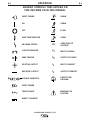
Graphic Symbols that appear on this machine or in this manual..........................B-2
Definition of Welding Terms...................................................................................B-3
General Description...............................................................................................B-4
Recommended Processes and Equipment ...........................................................B-4
Required Equipment..............................................................................................B-4
Limitations..............................................................................................................B-4
Duty Cycle and Time Period..................................................................................B-4
Case Front Controls........................................................................................B-5
Nominal Procedures........................................................................................B-6
Fringe Procedures...........................................................................................B-6
Making a Weld ................................................................................................B-6
Welding Adjustment ........................................................................................B-6
Constant Voltage Welding...............................................................................B-7
Pulse Welding .................................................................................................B-8
STT Welding ...................................................................................................B-9
________________________________________________________________________
Accessories.....................................................................................................Section C
Optional Equipment...............................................................................................C-1
Factory Installed..............................................................................................C-1
Field Installed..................................................................................................C-1
Compatible Lincoln Equipment .......................................................................C-1
________________________________________________________________________
Maintenance ....................................................................................................Section D
Safety Precautions ................................................................................................D-1
Routine Maintenance ............................................................................................D-1
Periodic Maintenance............................................................................................D-1
Calibration Specification........................................................................................D-1
________________________________________________________________________

ix
ix
TABLE OF CONTENTS
Page
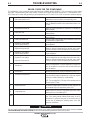
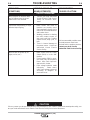
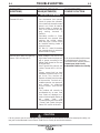
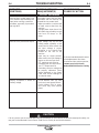
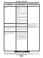
Troubleshooting ..............................................................................................Section E
How to use Troubleshooting Guide .......................................................................E-1
Using the Status LED to Troubleshoot System Problems.....................................E-2
Error Codes For Power Waves .............................................................................E-3
Troubleshooting Guide ............................................................................E-4 thru E-7
________________________________________________________________________
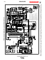
Wiring Diagram ............................................................................................Section F-1
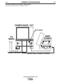
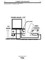
Connection Diagrams...........................................................................Section F-2, F-3
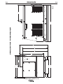
Dimension Print............................................................................................Section F-4
________________________________________________________________________
Parts Lists....................................................................................................P450 Series
________________________________________________________________________

A-1
INSTALLATION
POWER WAVE 455M/STT (CE)
A-1
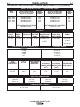
TECHNICAL SPECIFICATIONS - POWER WAVE 455M/STT (CE) (K2203-2)
OUTPUT
RECOMMENDED INPUT WIRE AND FUSE SIZES
PHYSICAL DIMENSIONS
TEMPERATURE RANGES
INPUT AT RATED OUTPUT - THREE PHASE ONLY
INPUT
VOLTS
380V - 60Hz.
380V - 50Hz.
415V - 60Hz.
415V - 50Hz.
OPEN
CIRCUIT
VOLTAGE
75 VDC
INPUT
VOLTAGE /
FREQUENCY
380V Hz.
415V Hz.
HEIGHT
663 mm
(26.10 in)
WIDTH
505 mm
(19.86 in)
DEPTH
835 mm
(32.88 in)
WEIGHT
121 kg.
(267 lbs.)
TYPE 75°C
(SUPER LAG)
OR BREAKER
SIZE (AMPS)
40 A
40 A
TYPE 75°C
GROUND WIRE
IN CONDUIT
AWG[IEC] SIZES
(mm
2
)
10 (6)
10 (6)
TYPE 75°C
COPPER WIRE
IN CONDUIT
AWG[IEC] SIZES
(mm
2
)
8 (10)
8 (10)
INPUT AMPERE
RATING ON
NAMEPLATE
36 A
33 A
DUTY
CYCLE
100%
100%
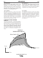
MIG/MAG
FCAW
SMAW
Pulse
STT
50-500 A
40-500 A
30-500 A
5-750 A
40-325 A
PULSE
VOLTAGE
RANGE
5 - 55 VDC
AUXILIARY
POWER
40 VDC AT
10 AMPS
220 VAC AT
5 AMPS
PULSE AND
BACKGROUND
TIME RANGE
100 MICRO SEC.
-
3.3 SEC.
STT PARAMETERS
PEAK & BACK-
GROUND CURRENT
15-450 AMPS
CURRENT
RANGE
AMPS
5 - 570 A
PULSE
FREQUENCY
0.15 - 1000 Hz
INPUT
CURRENT
AMPS
36 A
36 A
33 A
33 A
INPUT
CURRENT
AMPS
48 A
48 A
44 A
44 A
OUTPUT CONDITIONS
AMPS / VOLTS / DUTY CYCLE
EXCEPT STT PROCESS
400A@36V. 100%
400A@36V. 100%
400A@36V. 100%
400A@36V. 100%
STT PROCESS ALL VOLTAGES
325A@33V. 100%
OUTPUT CONDITIONS
AMPS / VOLTS / DUTY CYCLE
EXCEPT STT PROCESS
500A@40V. 60%
500A@40V. 60%
500A@40V. 60%
500A@40V. 60%
STT PROCESS ALL VOLTAGES
325A@33V. 100%
OPERATING TEMPERATURE RANGE
-20°C to 40°C
STORAGE TEMPERATURE RANGE
-40°C to 40°C
PROCESS CURRENT RANGE (DC) CURRENT AMPS

LIFTING
Lift the machine by the lift bail only. The lift bail is
designed to lift the power source only. Do not attempt
to lift the Power Wave with accessories attached to it.
STACKING
Power Wave machines can be stacked to a maximum
of 3 high.
The bottom machine must always be placed on a
firm, secure, level surface. There is a danger of
machines toppling over if this precaution is not
taken.
-------------------------------------------------------------
MACHINE GROUNDING
The frame of the welder must be grounded. A ground
terminal marked with the symbol is located inside
the reconnect/input access door for this purpose. See
your local and national electrical codes for proper
grounding methods.
HIGH FREQUENCY PROTECTION
Locate the Power Wave away from radio controlled
machinery.
The normal operation of the Power Wave may
adversely affect the operation of RF controlled
equipment, which may result in bodily injury or
damage to the equipment.
SAFETY PRECAUTIONS Read this
entire installation section before you start installa-
tion.
ELECTRIC SHOCK can kill.
• Only qualified personnel should per-
form this installation.
• Turn the input power OFF at the
disconnect switch or fuse box before
working on this equipment. Turn off
the input power to any other equipment connected
to the welding system at the disconnect switch or
fuse box before working on the equipment.
• Do not touch electrically hot parts.
• Always connect the Power Wave 455M/STT (CE)
grounding lug (located inside the reconnect input
access door) to a proper safety (Earth) ground.
----------------------------------------------------------
SELECT SUITABLE LOCATION
Do not use Power Wave 455M/STT (CE) in outdoor
environments. The Power Wave 455M/STT (CE) power
source should not be subjected to falling water, nor
should any parts of it be submerged in water. Doing so
may cause improper operation as well as pose a safe-
ty hazard. The best practice is to keep the machine in
a dry, sheltered area.
Do not mount the Power Wave 455M/STT (CE) over
combustible surfaces. Where there is a combustible
surface directly under stationary or fixed electrical
equipment, that surface shall be covered with a steel
plate at least 1.6mm (.060") thick, which shall extend
not less than 150mm (5.90") beyond the equipment on
all sides.
Place the welder where clean cooling air can freely cir-
culate in through the rear louvers and out through the
case sides and bottom. Dirt, dust, or any foreign mate-
rial that can be drawn into the welder should be kept at
a minimum. Do not use air filters on the air intake
because the air flow will be restricted. Failure to
observe these precautions can result in excessive oper-
ating temperatures and nuisance shutdowns.
Machines are equipped with F.A.N. (fan as needed) cir-
cuitry. The fan runs whenever the output is enabled,
whether under loaded or open circuit conditions. The
fan also runs for a period of time (approximately 5 min-
utes) after the output is disabled, to ensure all compo-
nents are properly cooled.
If desired, the F.A.N. feature can be disabled (causing the
fan to run whenever the power source is on). To disable
F.A.N., connect leads 444 and X3A together at the output
of the solid state fan control relay, located on the back of
the Control PC board enclosure. (See Wiring Diagram)
A-2
INSTALLATION
POWER WAVE 455M/STT (CE)
A-2
WARNING
• Lift only with equipment of
adequate lifting capacity.
• Be sure machine is stable
when lifting.
• Do not lift this machine using
lift bail if it is equipped with a
heavy accessory such as trail-
er or gas cylinder.
FALLING • Do not lift machine if lift bail is
EQUIPMENT can damaged.
cause injury. • Do not operate machine while
suspended from lift bail.
Do not stack the Power Wave 455M/STT (CE) on
top of any other machine.
------------------------------------------------------------------------
WARNING
CAUTION

A-3
INSTALLATION
POWER WAVE 455M/STT (CE)
A-3
INPUT CONNECTION
Only a qualified electrician should connect the
input leads to the Power Wave 455M/STT (CE).
Connections should be made in accordance with
all local and national electrical codes and the con-
nection diagram located on the inside of the
reconnect/input access door of the machine.
Failure to do so may result in bodily injury or death.
-------------------------------------------------------------
Use a three-phase supply line. A 45 mm (1.75 inch)
diameter access hole for the input supply is located on
the upper left case back next to the input access door.
Connect L1, L2, L3 and ground according to the Input
Supply Connection Diagram decal located on the
inside of the input access door or refer to Figure A.1.
INPUT FUSE AND SUPPLY WIRE
CONSIDERATIONS
Refer to the Technical Specifications at the beginning
of this Installation section for recommended fuse and
wire sizes. Fuse the input circuit with the recommend-
ed super lag fuse or delay type breakers (also called
“inverse time” or “thermal/magnetic” circuit breakers).
Choose an input and grounding wire size according to
local or national electrical codes. Using fuses or circuit
breakers smaller than recommended may result in
“nuisance” shut-offs from welder inrush currents, even
if the machine is not being used at high currents.
NOTE: Turn main input power to the machine OFF before performing connection procedure. Failure to do
so will result in damage to the machine.
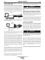
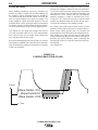
FIGURE A.1 - CONNECTION DIAGRAM ON CONNECTION/INPUT ACCESS DOOR
ELECTRODE AND WORK CABLE
CONNECTIONS
Connect a work lead of sufficient size and length (Per
Table 1) between the proper output terminal on the power
source and the work. Be sure the connection to the work
makes tight metal-to-metal electrical contact. To avoid
interference problems with other equipment and to
achieve the best possible operation, route all cables
directly to the work and wire feeder. Avoid excessive
lengths and do not coil excess cable.
Minimum work and electrode cables sizes are as follows:
TABLE A.1
Current (60% Duty Cycle) MINIMUM COPPER
WORK CABLE SIZE AWG
Up To-30 m Length (100 Ft.)
400 Amps 67 mm
2
(2/0)
500 Amps 85 mm
2
(3/0)
600 Amps 85 mm
2
(3/0)
NOTE: K1796 coaxial welding cable is recommended to
reduce the cable inductance in long cable lengths. This is
especially important in Pulse and STT applications.
When using inverter type power sources like the
Power Waves, use the largest welding (electrode and
ground) cables that are practical. At least 67 mm
2
(2/0) copper wire - even if the average output current
would not normally require it. When pulsing, the
pulse current can reach very high levels. Voltage
drops can become excessive, leading to poor welding
characteristics, if undersized welding cables are
used.
------------------------------------------------------------------------
CAUTION
W / L3
V / L2
U / L1
THE LINCOLN ELECTRIC CO. CLEVELAND, OHIO U.S.A.
XA
S24190
use or service this equipment.
Do not touch electrically live parts.
removed.
Only qualified persons should install,
Do not operate with covers
inspecting or servicing machine.
Disconnect input power before
.
.
.
.
CR1
INPUT SUPPLY CONNECTION DIAGRAM
WARNING

A-4
INSTALLATION
POWER WAVE 455M/STT (CE)
A-4
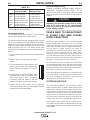
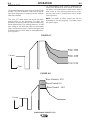
CABLE INDUCTANCE, AND ITS EFFECTS
ON PULSE WELDING
For Pulse Welding processes, cable inductance will cause the
welding performance to degrade. For the total welding loop
length less than
15.24m (50 ft.), traditional welding cables
may be used without any effects on welding performance. For
the total welding loop length greater than
15.24m (50 ft.), the
K1796 Coaxial Welding Cables are recommended. The weld-
ing loop length is defined as the total of electrode cable length
(A) + work cable length (B) + work length (C) (See Figure A.3).
For long work piece lengths, a sliding work connection should
be considered to keep the total welding loop length less than
50 feet. (See Figure A.4.)
Output connections on some Power Waves are made via 1/2-
13 threaded output studs located beneath the spring loaded
output cover at the bottom of the case front.
Most welding applications run with the electrode being posi-
tive (+). For those applications, connect the electrode cable
between the wire feeder and the positive (+) output stud on
the power source (located beneath the spring loaded output
cover near the bottom of the case front). Connect the other
end of the electrode cable to the wire drive feed plate. The
electrode cable lug must be against the feed plate. Be sure
the connection to the feed plate makes tight metal-to-metal
electrical contact. The electrode cable should be sized
according to the specifications given in the work cable con-
nections section. Connect a work lead from the negative (-)
power source output stud to the work piece. The work piece
connection must be firm and secure, especially if pulse weld-
ing is planned.
When welding with the STT process, use the positive output
connection labeled “STT” for STT welding. (If desired ,other
welding modes can be used on this stud; however, the aver-
age output current will be limited to 325 amps.) For non-STT
processes, use the positive output connection labeled “Power
Wave”, so that the full output range of the machine is avail-
able.
Do Not connect the STT and Power Wave stud together.
Paralleling the connection will bypass the STT circuitry and
severely deteriorate STT welding performance.
For additional Safety information regarding the electrode and
work cable set-up, See the standard "SAFETY INFORMA-
TION" located in the front of the Instruction Manuals.
Excessive voltage drops caused by poor work piece con-
nections often result in unsatisfactory welding perform-
ance.
------------------------------------------------------------------------
NEGATIVE ELECTRODE POLARITY
When negative electrode polarity is required, such as in some
Innershield applications, reverse the output connections at
the power source (electrode cable to the negative (-) stud,
and work cable to the positive (+) stud).
When operating with electrode polarity negative the
"Electrode Sense Polarity" DIP switch must be set to the
"Negative" position on the Wire Drive Feed Head PC Board.
The default setting of the switch is positive electrode polarity.
Consult the Power Feed instruction manual for further details.
VOLTAGE SENSING
The best arc performance occurs when the Power Waves
have accurate data about the arc conditions. Depending
upon the process, inductance within the electrode and
work lead cables can influence the voltage apparent at the
studs of the welder. Voltage sense leads improve the
accuracy of the arc conditions and can have a dramatic
effect on performance. Sense Lead Kits (K940-10, -25 or
-50) are available for this purpose.
If the voltage sensing is enabled but the sense leads are
missing, improperly connected, or if the electrode polar-
ity switch is improperly configured, extremely high weld-
ing outputs may occur.
------------------------------------------------------------------------
The ELECTRODE sense lead (67) is built into the control
cable, and is automatically enabled for all semi-automatic
processes. The WORK sense lead (21) connects to the
Power Wave 455M/STT (CE) at the four pin connector locat-
ed underneath the output stud cover. By default the WORK
voltage is monitored at the output stud in the Power Wave
455M/STT (CE). For more information on the WORK sense
lead (21), see "Work Voltage Sensing” in the following para-
graph.
All constant current processes sense the voltage at the out-
put studs of the POWER WAVE 455M/STT (CE) by default.
CAUTION
CAUTION
B
A
C
FIGURE A.3
POWER
WAVE
WORK
A
C
B
POWER
WAVE
FIGURE A.4
K1796 COAXIAL CABLE
MEASURE FROM END
OF OUTER JACKET OF
CABLE
C
A
B
WORK
SLIDING WORK CONNECTION
FIGURE A.4

A-5
INSTALLATION
POWER WAVE 455M/STT (CE)
A-5
Electrode Voltage Sensing
Enabling or disabling electrode voltage sensing is
automatically configured through software. The 67
electrode sense lead is internal to the cable to the wire
feeder and always connected when a wire feeder is
present.
Important: The electrode polarity must be config-
ured at the feed head for all semi-automatic
processes. Failure to do so may result in extreme-
ly high welding outputs.
------------------------------------------------------------------------
POWER WAVE TO SEMI-AUTOMAT-
IC POWER FEED WIRE FEEDER
INTERCONNECTIONS
The Power Wave 455M/STT (CE) and semi-automatic
POWER FEED family communicate via a 5 conductor
control cable (K1543). The control cable consists of two
power leads, one twisted pair for digital communication,
and one lead for voltage sensing. The cables are
designed to be connected end to end for ease of exten-
sion. The output receptacle on the Power Wave
455M/STT (CE) is located beneath the spring loaded out-
put cover at the bottom of the case front. The input recep-
tacle on the Power Feed is typically located at the back of
the feeder, or on the bottom of the user interface.
For convenience sake, the electrode and control cables
can be routed behind the left or right strain reliefs (under
the spring loaded output cover), and along the channels
formed into the base of the Power Wave, out the back of
the channels, and then to the wire feeder.
Due to the flexibility of the platform the configuration may
vary. The following is a general description of the system.
For specific configuration information, consult the semi-
automatic Power Feed instruction manual.
SYSTEM DESCRIPTION
The Power Wave 455M/STT (CE) and Power Feed M
family of products utilize a digital communication system
called ArcLink. Simply put, ArcLink allows large amounts
of information to be passed at very high speeds between
components (nodes) in the system. The system requires
only two wires for communication, and because of its bus-
like structure, the components may be connected to the
network in any order, thus simplifying the system set-up.
Each "system" must contain only one power source.
The number of wire feeders is determined by the type
of wire feeder. Refer to the wire feeder instruction man-
ual for details
Enable the voltage sense leads as follows:
TABLE A.2
Process Electrode Voltage Work Voltage
Sensing 67 lead * Sensing 21 lead
GMAW 67 lead required 21 lead optional
GMAW-P
67 lead required 21 lead optional
FCAW 67 lead required 21 lead optional
STT 67 lead required 21 lead required
GTAW
Voltage sense at studs Voltage sense at studs
GMAW
Voltage sense at studs Voltage sense at studs
SAW 67 lead required 21 lead optional
CAC
Voltage sense at studs Voltage sense at studs
* The electrode voltage 67 sense lead is integral to the
control cable to the wire feeder.
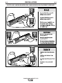
Work Voltage Sensing
The standard Power Wave 455M/STT
(CE) is shipped
with the work voltage sense lead enabled.
For processes requiring work voltage sensing, connect
the (21) work voltage sense lead (K940) from the Power
Wave work sense lead receptacle to the work piece.
Attach the sense lead to the work piece as close to the
weld as practical, but not in the return current path.
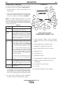
Enable the work voltage sensing in the Power Wave as
follows:
1. Turn off power to the power source at the disconnect
switch.
2. Remove the front cover from the power
source.
3. The control board is on the left side of the
power source. Locate the 8-position DIP
switch and look for switch 8 of the DIP
switch.
4. Using a pencil or other small object, slide
the switch right to the OFF position if the
work sense lead is NOT connected.
Conversely, slide the switch to the ON
position if the work sense lead is present.
5. Replace the cover and screws. The PC board will
“read” the switch at power up, and configure the work
voltage sense lead appropriately.
O
N
12345678
CAUTION

A-6
INSTALLATION
POWER WAVE 455MSTT (CE)
A-6
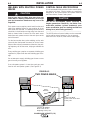
CONFIGURING THE SYSTEM
For codes below 11100, consult the semi-automatic
Power Feed instruction manual for configuration infor-
mation about DIP switch settings.
For codes above 11100 the power source will “Auto
Map” the system eliminating most of the need to set
DIP switches to configure the system.
If a system can not be “Auto Mapped” then the status
light on the power source will blink green fast and the
welder output will be disabled. If a system is not “Auto-
mappable”, then consult the instruction manual for the
accessory being used for configuration information
about DIP switch settings, or consult your local Lincoln
sales representative.
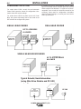
POWER WAVE
455M/STT (CE)
ROBOT
PLC CONTROLLER
ANALOG INTERFACE
etc.
POWER WAVE
455M/STT (CE)
POWER WAVE
455M/STT (CE)
POWER WAVE
455M/STT (CE)
FEED HEAD
SINGLE HEAD FEEDER DUAL HEAD FEEDER
SINGLE HEAD BOOM FEEDER
FH 1
PF-10R
UP TO 4 FEEDERS
ALLOWED
UP TO 4 FEED HEADS
ALLOWED
WIRE
DRIVE
MODULE
Typical Robotic/ Hard Automation
(using Wire Drive Module and PF-10R)

A-7
INSTALLATION
POWER WAVE 455M/STT (CE)
A-7
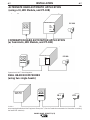
In this case the individual feed heads need to be assigned to the dual head control and the PW455M/STT (CE)
auto mapping disabled and the Equipment Groups set. (See the Feeder documentation for information on setting
the feeder DIP switches)
System that is NOT "Auto Mappable"
POWER WAVE 455M/STT (CE)
POWER WAVE 455M/STT (CE)
POWER WAVE
455M/STT (CE)
DUAL HEAD
DUAL HEAD
ALTERNATE HARD AUTOMATIC APPLICATION
(using a UI, WD Module, and PF-10R)
COMBINATION HARD AUTOMATION APPLICATION
(w/ Semi-Auto, WD Module, and PF-10R)
DUAL HEAD BOOM FEEDER
(using two single heads)
PF-10R
FH-1
FH-2
PF-10R
WIRE
DRIVE
MODULE
(FH1)
WIRE
DRIVE
MODULE
(FH1)

A-8
INSTALLATION
POWER WAVE 455M/STT (CE)
A-8
WELDING WITH MULTIPLE POWER
WAVES
Special care must be taken when more than one
Power Wave is welding simultaneously on a single
part. Arc blow and arc interference may occur or be
magnified.
Each power source requires a work lead from the work
stud to the welding fixture. Do not combine all of the
work leads into one lead. The welding travel directions
should be in the direction moving away from the work
lead as shown below. Connect all of the work sense
leads from each power source to the work piece at the
end of the weld.
For the best results when pulse welding, set the wire
size and wire feed speed the same for all the Power
Waves. When these parameters are identical, the puls-
ing frequency will be the same, helping to stabilize the
arcs.
Every welding gun requires a separate shielding gas
regulator for proper flow rate and shielding gas cover-
age.
Do not attempt to supply shielding gas for two or more
guns from only one regulator.
If an anti-spatter system is in use then each gun must
have its own anti-spatter system. (See Figure A.2)
FIGURE A.2
-
+
POWERWAVE
Connect All Work
Sense Leads at the End
of the Joint
Connect All Welding
Work Leads at the
Beginning of the Joint
Travel
Direction
-
+
POWER WAVE
-
+
POWERWAVE
-
+
POWER WAVE
TWO POWER WAVES
CONTROL CABLE SPECIFICATIONS
It is recommended that genuine Lincoln control cables
be used at all times. Lincoln cables are specifically
designed for the communication and power needs of
the Power Wave / Power Feed system.
The use of non-standard cables, especially in
lengths greater than 7.6m(25 ft)., can lead to com-
munication problems (system shutdowns), poor
motor acceleration (poor arc starting) and low wire
driving force (wire feeding problems).
------------------------------------------------------------------------
The K1543 series of control cables can be connected
end to end for ease of extension. Do not exceed
more than 30.5 m(100 ft.) total control cable length.
CAUTION
CAUTION

A-9
INSTALLATION
POWER WAVE 455M/STT (CE)
A-9
MULTIPLE ARC UNSYNCHRONIZED SENSE LEAD AND WORK LEAD PLACEMENT GUIDELINES

A-10
INSTALLATION
POWER WAVE 455M/STT (CE)
A-10
I / O RECEPTACLE SPECIFICATIONS
TABLE 3
WIRE FEEDER RECEPTACLE S1
PIN LEAD# FUNCTION
A 53 Communication Bus L
B 54 Communication Bus H
C 67A Electrode Voltage Sense
D 52 0vdc
E 51 +40vdc
TABLE 4
VOLTAGE SENSE RECEPTACLE S2
PIN LEAD# FUNCTION
3 21A Work Voltage Sense
TABLE 5
RS232 RECEPTACLE S3
PIN LEAD# FUNCTION
2 253 RS232 Receive
3 254 RS232 Transmit
4 # S3 Pin5
5 # S3 Pin4
6 # # S3 Pin20
20 # # S3 Pin6
7 251 RS232 Common
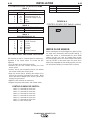
DIP SWITCH SETTINGS AND LOCATIONS
DIP switches on the P.C. Boards allow for custom con-
figuration of the Power Wave. To access the DIP
switches:
• Turn off power at the disconnect switch.
• Remove the top four screws securing the front
access panel.
• Loosen, but do not completely remove, the bottom
two screws holding the access panel.
• Open the access panel, allowing the weight of the
panel to be carried by the bottom two screws. Make
sure to prevent the weight of the access panel from
hanging on the harness.
• Adjust the DIP switches as necessary.
• Replace the panel and screws, and restore power.
CONTROL BOARD DIP SWITCH:
switch 1 = reserved for future use
switch 2 = reserved for future use
switch 3 = reserved for future use
switch 4 = reserved for future use
switch 5 = reserved for future use
switch 6 = reserved for future use
switch 7 = reserved for future use
switch 8 = work sense lead
switch 8
work sense lead
off work sense lead not connected
on work sense lead connected
WATER FLOW SENSOR
Water cooled guns can be damaged very quickly if they
are used even momentarily without water flowing. A
water flow sensor is recommended for those water
coolers that do not have an integral flow sensor.
Recommended practice is to install a water flow sensor
such as K1536-1 on the water return line of the torch.
When fully integrated into the welding system, the sen-
sor will prevent welding if no water flow is present.
CONTROL BOARD (DIP Switch Location)
FIGURE A.3
La page est en cours de chargement...
La page est en cours de chargement...
La page est en cours de chargement...
La page est en cours de chargement...
La page est en cours de chargement...
La page est en cours de chargement...
La page est en cours de chargement...
La page est en cours de chargement...
La page est en cours de chargement...
La page est en cours de chargement...
La page est en cours de chargement...
La page est en cours de chargement...
La page est en cours de chargement...
La page est en cours de chargement...
La page est en cours de chargement...
La page est en cours de chargement...
La page est en cours de chargement...
La page est en cours de chargement...
La page est en cours de chargement...
La page est en cours de chargement...
La page est en cours de chargement...
La page est en cours de chargement...
La page est en cours de chargement...
La page est en cours de chargement...
La page est en cours de chargement...
La page est en cours de chargement...
-
 1
1
-
 2
2
-
 3
3
-
 4
4
-
 5
5
-
 6
6
-
 7
7
-
 8
8
-
 9
9
-
 10
10
-
 11
11
-
 12
12
-
 13
13
-
 14
14
-
 15
15
-
 16
16
-
 17
17
-
 18
18
-
 19
19
-
 20
20
-
 21
21
-
 22
22
-
 23
23
-
 24
24
-
 25
25
-
 26
26
-
 27
27
-
 28
28
-
 29
29
-
 30
30
-
 31
31
-
 32
32
-
 33
33
-
 34
34
-
 35
35
-
 36
36
-
 37
37
-
 38
38
-
 39
39
-
 40
40
-
 41
41
-
 42
42
-
 43
43
-
 44
44
-
 45
45
-
 46
46


Lincoln Electric IM808-A Manuel utilisateur
- Catégorie
- Système de soudage
- Taper
- Manuel utilisateur
- Ce manuel convient également à
dans d''autres langues
- English: Lincoln Electric IM808-A User manual
Documents connexes
-
Lincoln Electric 455 M Manuel utilisateur
-
-
-
-
-
-
-