La page est en cours de chargement...

DOC023.97.93069
Hach 9586sc Oxygen
Scavenger Analyzer
05/2018, Edition 6
Basic User Manual
Manuel d'utilisation de base
Manual básico del usuario
基本用户手册

English..............................................................................................................................3
Français......................................................................................................................... 24
Español.......................................................................................................................... 47
中文................................................................................................................................. 70
2

Table of contents
Specifications on page 3 Operation on page 19
General information on page 5 Maintenance on page 21
Installation on page 7 Troubleshooting on page 22
Startup on page 16 Replacement parts and accessories on page 22
User interface and navigation on page 16
Expanded manual version
For additional information, refer to the expanded version of this manual, which is available on the
manufacturer's website.
Specifications
Specifications are subject to change without notice.
Panel
Specification Details
Dimensions 817 x 300 x 140 mm (32.2 x 11.8 x 5.5 in)
Weight 14.6 kg (32.15 lbs)
Sample flow rate 10—15 liters/hour
Working pressure 0.5—6 bar (7—87 psi)
Ambient temperature 0—60 °C (-32—140 °F)
Relative humidity 10—90%
Working electrode Platinum
Counter electrode Stainless steel
Reference Ag / AgCl / KCl 0.1 M
Measuring cell Acrylic
Sample conditioner DIPA (diisopropylamine)
European standards EN 61326 Class A for EMC; EN 601010-1 for low voltage safety
International standards cETLus
Sensor
Specification Details
Measuring range 0—500 ppb hydrazine; 0—100 ppb carbohydrazide
Sensitivity < 0.2 ppb
Repeatability 1 ppb or ± 2% of measurement whichever is the greater
Detection limit ≤ 1 ppb
Response time < 60 seconds
Sample temperature measurement range 5—45 °C (41—113 °F)
English 3

Controller
Specification Details
Component description Microprocessor-controlled and menu-driven controller that operates the sensor and
displays measured values.
Operating temperature -20 to 60 ºC (-4 to 140 ºF); 95% relative humidity, non-condensing with sensor load
<7 W; -20 to 50 ºC (-4 to 104 ºF) with sensor load <28 W
Storage temperature -20 to 70 ºC (-4 to 158 ºF); 95% relative humidity, non-condensing
Enclosure
1
NEMA 4X/IP66 metal enclosure with a corrosion-resistant finish
Power requirements AC powered controller: 100-240 VAC ±10%, 50/60 Hz; Power 50 VA with 7 W
sensor/network module load, 100 VA with 28 W sensor/network module load
(optional Modbus, RS232/RS485, Profibus DPV1 or HART network connection).
24 VDC powered controller: 24 VDC—15%, + 20%; Power 15 W with 7 W
sensor/network module load, 40 W with 28 W sensor/network module load (optional
Modbus, RS232/RS485, Profibus DPV1 or HART network connection).
Altitude requirements Standard 2000 m (6562 ft) ASL (Above Sea Level)
Pollution
degree/Installation
category
Polution Degree 2; Installation Category II
Outputs Two analog (0-20 mA or 4-20 mA) outputs. Each analog output can be assigned to
represent a measured parameter such as pH, temperature, flow or calculated
values. Optional module supplies three additional analog outputs (5 total).
Relays Four SPDT, user-configured contacts, rated 250 VAC, 5 Amp resistive maximum for
the AC powered controller and 24 VDC, 5A resistive maximum for the DC powered
controller. Relays are designed for connection to AC Mains circuits (i.e., whenever
the controller is operated with 115 - 240 VAC power) or DC circuits (i.e., whenever
the controller is operated with 24 VDC power).
Dimensions ½ DIN—144 x 144 x 180.9 mm (5.7 x 5.7 x 7.12 in.)
Weight 1.7 kg (3.75 lb)
EMC requirements EN61326-1: EMC Directive
Note: This is a Class A product. In a domestic environment this product may cause radio
interference in which case the user may be required to take adequate measures.
Korean registration
User Guidance for EMC Class A Equipment
업무용을 위한 EMC 등급 A 장치에 대한
사용자 지침
사용자안내문
A 급 기기 ( 업무용 방송통신기자재 )
이 기기는 업무용 (A 급 ) 전자파적합기기로서 판매자 또는 사용자는 이 점을 주의하
시기 바라며 , 가정외의 지역에서 사용하는 것을 목적으로 합니다.
CE compliance EN61010-1: LVD Directive
Digital communication Optional Modbus, RS232/RS485, Profibus DPV1 or HART network connection for
data transmission
Data logging Secure Digital Card (32 GB maximum) or special RS232 cable connector for data
logging and performing software updates. The controller will keep approximately
20,000 data points per sensor.
Warranty 2 years
1
Units that have the Underwriters Laboratories (UL) certification are intended for indoor use only
and do not have a NEMA 4X/IP66 rating.
4 English

General information
In no event will the manufacturer be liable for direct, indirect, special, incidental or consequential
damages resulting from any defect or omission in this manual. The manufacturer reserves the right to
make changes in this manual and the products it describes at any time, without notice or obligation.
Revised editions are found on the manufacturer’s website.
Safety information
N O T I C E
The manufacturer is not responsible for any damages due to misapplication or misuse of this product including,
without limitation, direct, incidental and consequential damages, and disclaims such damages to the full extent
permitted under applicable law. The user is solely responsible to identify critical application risks and install
appropriate mechanisms to protect processes during a possible equipment malfunction.
Please read this entire manual before unpacking, setting up or operating this equipment. Pay
attention to all danger and caution statements. Failure to do so could result in serious injury to the
operator or damage to the equipment.
Make sure that the protection provided by this equipment is not impaired. Do not use or install this
equipment in any manner other than that specified in this manual.
Use of hazard information
D A N G E R
Indicates a potentially or imminently hazardous situation which, if not avoided, will result in death or serious injury.
W A R N I N G
Indicates a potentially or imminently hazardous situation which, if not avoided, could result in death or serious
injury.
C A U T I O N
Indicates a potentially hazardous situation that may result in minor or moderate injury.
N O T I C E
Indicates a situation which, if not avoided, may cause damage to the instrument. Information that requires special
emphasis.
Precautionary labels
Read all labels and tags attached to the instrument. Personal injury or damage to the instrument
could occur if not observed. A symbol on the instrument is referenced in the manual with a
precautionary statement.
This is the safety alert symbol. Obey all safety messages that follow this symbol to avoid potential
injury. If on the instrument, refer to the instruction manual for operation or safety information.
This symbol indicates that a risk of electrical shock and/or electrocution exists.
This symbol indicates the presence of devices sensitive to Electro-static Discharge (ESD) and
indicates that care must be taken to prevent damage with the equipment.
This symbol, when noted on a product, indicates the instrument is connected to alternate current.
Electrical equipment marked with this symbol may not be disposed of in European domestic or
public disposal systems. Return old or end-of-life equipment to the manufacturer for disposal at no
charge to the user.
English 5

Products marked with this symbol indicates that the product contains toxic or hazardous substances
or elements. The number inside the symbol indicates the environmental protection use period in
years.
Products marked with this symbol indicates that the product conforms to relevant South Korean
EMC standards.
Certification
Canadian Radio Interference-Causing Equipment Regulation, IECS-003, Class A:
Supporting test records reside with the manufacturer.
This Class A digital apparatus meets all requirements of the Canadian Interference-Causing
Equipment Regulations.
FCC Part 15, Class "A" Limits
Supporting test records reside with the manufacturer. The device complies with Part 15 of the FCC
Rules. Operation is subject to the following conditions:
1. The equipment may not cause harmful interference.
2. The equipment must accept any interference received, including interference that may cause
undesired operation.
Changes or modifications to this equipment not expressly approved by the party responsible for
compliance could void the user's authority to operate the equipment. This equipment has been tested
and found to comply with the limits for a Class A digital device, pursuant to Part 15 of the FCC rules.
These limits are designed to provide reasonable protection against harmful interference when the
equipment is operated in a commercial environment. This equipment generates, uses and can
radiate radio frequency energy and, if not installed and used in accordance with the instruction
manual, may cause harmful interference to radio communications. Operation of this equipment in a
residential area is likely to cause harmful interference, in which case the user will be required to
correct the interference at their expense. The following techniques can be used to reduce
interference problems:
1. Disconnect the equipment from its power source to verify that it is or is not the source of the
interference.
2. If the equipment is connected to the same outlet as the device experiencing interference, connect
the equipment to a different outlet.
3. Move the equipment away from the device receiving the interference.
4. Reposition the receiving antenna for the device receiving the interference.
5. Try combinations of the above.
Product components
Make sure that all components have been received. If any items are missing or damaged, contact the
manufacturer or a sales representative immediately.
6
English

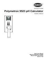
Product overview
The analyzer is designed to continuously measure the amount of oxygen scavengers (hydrazine or
carbohydrazide) in water.
Figure 1 Front and rear view
1 Controller 6 Chemical zero cartridge (option)
2 Measuring cell 7 Pressure regulator
3 Chemical zero on/off (option) 8 Sample in, 4/6 mm tube
4 Flow meter 9 Sample drain, 6/8 mm tube, atmospheric pressure
5 Sample conditioning bottle (DIPA)
Installation
C A U T I O N
Multiple hazards. Only qualified personnel must conduct the tasks described in this section of the
document.
English 7

Analyzer mounting
C A U T I O N
Personal injury hazard. Instruments or components are heavy. Use assistance to install or move. Make sure that
the wall mounting is able to hold 4 times the weight of the equipment.
N O T I C E
The analyzer must be aligned vertically to guarantee accuracy.
Attach the analyzer to a stable, vertical surface. Use a level to make sure that the analyzer is
completely vertical. Refer to the guidelines that follow.
• Put the instrument in a location that has access for operation, service and calibration.
• Make sure that there is good view of the display and controls.
• Keep the instrument away from a heat source.
• Keep the instrument away from vibrations.
• Keep the sample tubing as short as possible to minimize the response time.
• Make sure that there is no air in the sample supply line.
8 English

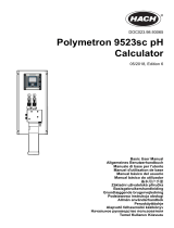
Wiring overview
Figure 2 shows an overview of the wiring connections inside the controller with the high voltage
barrier removed. The left side of the figure shows the back side of the controller cover.
Note: Remove connector caps from the connectors before module installation.
Figure 2 Wiring connections overview
1 Service cable connection 5 AC and DC power connector
2
9 Discrete input wiring connector
2
2 4-20 mA output
2
6 Ground terminals 10 Digital sensor connector
2
3 Sensor module connector 7 Relay connections
2
4 Communication module
connector (e.g., Modbus,
Profibus, HART, optional
4-20 mA module, etc.)
8 Digital sensor connector
2
High-voltage barrier
High-voltage wiring for the controller is located behind the high-voltage barrier in the controller
enclosure. The barrier must remain in place except when installing modules or when a qualified
installation technician is wiring for power, alarms, outputs or relays. Do not remove the barrier while
power is applied to the controller.
Wiring for power
W A R N I N G
Potential Electrocution Hazard. Always disconnect power to the instrument when making electrical
connections.
2
Terminals can be removed for improved access.
English 9

W A R N I N G
Potential Electrocution Hazard. If this equipment is used outdoors or in potentially wet locations, a
Ground Fault Interrupt device must be used for connecting the equipment to its mains power source.
D A N G E R
Electrocution Hazard. Do not connect AC power to a 24 VDC powered model.
W A R N I N G
Potential Electrocution Hazard. A protective earth (PE) ground connection is required for both
100-240 VAC and 24 VDC wiring applications. Failure to connect a good PE ground connection can
result in shock hazards and poor performance due to electromagnetic interferences. ALWAYS connect
a good PE ground to the controller terminal.
N O T I C E
Install the device in a location and position that gives easy access to the disconnect device and its operation.
The controller can be purchased as either a 100-240 VAC powered model or a 24 VDC powered
model. Follow the appropriate wiring instructions for the purchased model.
The controller can be wired for line power by hard-wiring in conduit or wiring to a power cord.
Regardless of the wire used, the connections are made at the same terminals. A local disconnect
designed to meet local electrical code is required and must be identified for all types of installation. In
hard-wired applications, the power and safety ground service drops for the instrument must be 18 to
12 AWG. Make sure that the field wiring insulation is rated 80 °C (176 °F) minimum.
Notes:
• The voltage barrier must be removed before making any electrical connections. After making all
connections, replace the voltage barrier before closing the controller cover.
• A sealing type strain relief and a power cord less than 3 meters (10 feet) in length with three 18-
gauge conductors (including a safety ground wire) can be used to maintain the NEMA
4X/IP66 environmental rating.
• Controllers can be ordered with AC power cords pre-installed. Additional power cords may also be
ordered.
• The DC power source that supplies power to the 24 VDC powered controller must maintain
voltage regulation within the specified 24 VDC-15% +20% voltage limits. The DC power source
must also provide adequate protection against surges and line transients.
Wiring procedure
Refer to the illustrated steps that follow and Table 1 or Table 2 to wire the controller for power. Insert
each wire into the appropriate terminal until the insulation is seated against the connector with no
bare wire exposed. Tug gently after insertion to make sure that there is a secure connection. Seal
any unused openings in the controller box with conduit opening sealing plugs.
Table 1 AC power wiring information (AC powered models only)
Terminal Description Color—North America Color—EU
1 Hot (L1) Black Brown
2 Neutral (N) White Blue
— Protective Earth (PE) Ground lug Green Green with yellow stripe
10 English

Table 2 DC power wiring information (DC powered models only)
Terminal Description Color—North America Color—EU
1 +24 VDC Red Red
2 24 VDC return Black Black
— Protective Earth (PE) Ground lug Green Green with yellow stripe
English 11

Alarms and relays
The controller is equipped with four unpowered, single pole relays rated 100-250 VAC, 50/60 Hz,
5 amp resistive maximum. Contacts are rated 250 VAC, 5 amp resistive maximum for the AC
powered controller and 24 VDC, 5A resistive maximum for the DC powered controller. The relays are
not rated for inductive loads.
Wiring relays
W A R N I N G
Potential Electrocution Hazard. Always disconnect power to the instrument when making electrical
connections.
W A R N I N G
Potential fire hazard. The relay contacts are rated 5A and are not fused. External loads connected to
the relays must have current limiting devices provided to limit current to < 5 A.
W A R N I N G
Potential fire hazard. Do not daisy-chain the common relay connections or jumper wire from the mains
power connection inside the instrument.
W A R N I N G
Potential electrocution hazard. In order to maintain the NEMA/IP environmental ratings of the
enclosure, use only conduit fittings and cable glands rated for at least NEMA 4X/IP66 to route cables in
to the instrument.
AC line (100—250 V) powered controllers
12
English

W A R N I N G
Potential electrocution hazard. AC mains powered controllers (115 V–230 V) are designed for relay
connections to AC mains circuits (i.e., voltages greater than 16 V-RMS, 22.6 V-PEAK or 35 VDC).
The wiring compartment is not designed for voltage connections in excess of 250 VAC.
24 VDC powered controllers
W A R N I N G
Potential electrocution hazard. 24 V powered controllers are designed for relay connections to low
voltage circuits (i.e., voltages less than 16 V-RMS, 22.6 V-PEAK or 35 VDC).
The 24 VDC controller relays are designed for the connection to low voltage circuits (i.e., voltages
less than 30 V-RMS, 42.2 V-PEAK or 60 VDC). The wiring compartment is not designed for voltage
connections above these levels.
The relay connector accepts 18–12 AWG wire (as determined by load application). Wire gauge less
than 18 AWG is not recommended. Make sure that the field wiring insulation is rated 80 °C (176 °F)
minimum.
The Normally Open (NO) and Common (COM) relay contacts will be connected when an alarm or
other condition is active. The Normally Closed (NC) and Common relay contacts will be connected
when an alarm or other condition is inactive (unless the Fail Safe is set to Yes) or when power is
removed from the controller.
Most relay connections use either the NO and COM terminals or the NC and COM terminals. The
numbered installation steps show connection to the NO and COM terminals.
English 13

Analog output connections
W A R N I N G
Potential Electrocution Hazard. Always disconnect power to the instrument when making electrical
connections.
W A R N I N G
Potential electrocution hazard. In order to maintain the NEMA/IP environmental ratings of the
enclosure, use only conduit fittings and cable glands rated for at least NEMA 4X/IP66 to route cables in
to the instrument.
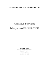
Two isolated analog outputs (1 and 2) are provided (Figure 3). Such outputs are commonly used for
analog signaling or to control other external devices.
Make wiring connections to the controller as shown in Figure 3 and Table 3.
Note: Figure 3 shows the back of the controller cover and not the inside of the main controller compartment.
Table 3 Output connections
Recorder wires Circuit board position
Output 2– 4
Output 2+ 3
Output 1– 2
Output 1+ 1
1. Open the controller cover.
2. Feed the wires through the strain relief.
3. Adjust the wire as necessary and tighten the strain relief.
14
English

4. Make connections with twisted-pair shielded wire and connect the shield at the controlled
component end or at the control loop end.
• Do not connect the shield at both ends of the cable.
• Use of non-shielded cable may result in radio frequency emission or susceptibility levels higher
than allowed.
• Maximum loop resistance is 500 ohm.
5. Close the controller cover and tighten the cover screws.
6. Configure outputs in the controller.
Figure 3 Analog output connections
Connect the optional digital communication output
The manufacturer supports Modbus RS485, Modbus RS232, Profibus DPV1 and HART
communication protocols. The optional digital output module is installed in the location indicated by
item 4 in Figure 2 on page 9. Refer to the instructions supplied with the network module for more
details.
For information about Modbus registers, go to http://www.de.hach.com or http://www.hach.com and
search Modbus registers or go to any sc200 product page.
Plumb the sample and drain lines
Connect the sample and drain lines to the fittings on the back of the panel.
1. Connect the sample line to the inlet 4/6-mm OD tube fitting.
2. Connect a drain line to the drain 6/8-mm OD tube fitting. Keep the drain line as short as possible
at atmospheric pressure.
English
15

Install the reagents
W A R N I N G
Chemical exposure hazard. Obey laboratory safety procedures and wear all of the personal protective
equipment appropriate to the chemicals that are handled. Refer to the current safety data sheets
(MSDS/SDS) for safety protocols.
1. Fill the empty sample conditioning bottle with DIPA (diisopropylamine) and enter the hazardous
reagent information on the blank label attached to the bottle.
2. Install the sample conditioning bottle on the front of the analyzer.
3. Connect the supplied tube to the measuring cell. Install the tube completely into the bottle of
conditioning solution. Make sure that the tube fittings are tight to prevent leakage of fumes from
the conditioning bottle into the atmosphere.
4. If the chemical zero cartridge is used, install the cartridge on the rear of the analyzer.
Startup
Make sure that the flow rate and pressure do not exceed the values in Specifications on page 3.
1. Open the valve on the sample line to let sample flow through the analyzer.
2. Turn the knob on the flow meter to set the flow rate.
3. Examine the plumbing for leaks and stop any leaks if found.
4. Apply power to the controller.
5. Make the applicable menu selections when the controller starts.
User interface and navigation
User interface
The keypad has four menu keys and four directional keys as shown in Figure 4.
16
English

Figure 4 Keypad and front panel overview
1 Instrument display 5 BACK key. Moves back one level in the menu
structure.
2 Cover for secure digital memory card slot 6 MENU key. Moves to the Settings Menu from other
screens and submenus.
3 HOME key. Moves to the Main Measurement
screen from other screens and submenus.
7 Directional keys. Used to navigate through the
menus, change settings, and increment or
decrement digits.
4 ENTER key. Accepts input values, updates, or
displayed menu options.
Inputs and outputs are set up and configured through the front panel using the keypad and display
screen. This user interface is used to set up and configure inputs and outputs, create log information
and calculated values, and calibrate sensors. The SD interface can be used to save logs and update
software.
Display
Figure 5 shows an example of the main measurement screen with the sensor connected to the
controller.
The front panel display screen shows sensor measurement data, calibration and configuration
settings, errors, warnings and other information.
English
17

Figure 5 Example of Main Measurement screen
1 Home screen icon 7 Warning status bar
2 Sensor name 8 Date
3 SD Memory card icon 9 Analog output values
4 Relay status indicator 10 Time
5 Measurement value 11 Progress bar
6 Measurement unit 12 Measurement parameter
Table 4 Icon descriptions
Icon Description
Home screen The icon may vary depending on the screen or menu being displayed. For example, if an SD
card is installed, an SD card icon appears here when the user is in the SD Card Setup menu.
SD memory
card
This icon appears only if an SD card is in the reader slot. When a user is in the SD Card Setup
menu, this icon appears in the upper left corner.
Warning A warning icon consists of an exclamation point within a triangle. Warning icons appear on the
right of the main display below the measurement value. Push the ENTER key then select the
device to view any problems associated with that device. The warning icon will no longer be
displayed once all problems have been corrected or acknowledged.
Error An error icon consists of an exclamation point within a circle. When an error occurs, the error
icon and the measurement screen flash alternately in the main display. To view errors, push the
MENU key and select Diagnostics. Then select the device to view any problems associated
with that device.
Additional display formats
• From the Main Measurement screen push the UP and DOWN arrow keys to switch between
measurement parameters
• From the Main Measurement screen push the RIGHT arrow key to switch to a split display of up to
4 measurement parameters. Push the RIGHT arrow key to include additional measurements. Push
the LEFT arrow key as needed to return to the Main Measurement screen
• From the Main Measurement screen push the LEFT arrow key to switch to the graphical display
(see Graphical display on page 18 to define the parameters). Push the UP and DOWN arrow
keys to switch measurement graphs
Graphical display
The graph shows concentration and temperature measurements for each channel in use. The graph
supplies easy monitoring of trends and shows changes in the process.
18
English

1. From the graphical display screen use the up and down arrow keys to select a graph and push
the HOME key.
2. Select an option:
Option Description
MEASUREMENT VALUE Set the measurement value for the selected channel. Select between Auto Scale
and Manually Scale. For manual scaling enter the minimum and maximum
measurement values
DATE & TIME RANGE Select the date and time range from the available options
Operation
Configure the sensor
Use the CONFIGURE menu to enter identification information for the sensor and to change options
for data handling and storage.
1. Push the menu key, select SENSOR SETUP>CONFIGURE.
2. Use the arrow keys to select an option and push enter. To enter numbers, characters or
punctuation, push and hold the up or down arrow keys. Push the right arrow key to advance to
the next space.
Option Description
EDIT NAME Changes the name that corresponds to the sensor on the top of the measure screen.
The name is limited to 16 characters in any combination of letters, numbers, spaces or
punctuation.
SENSOR S/N Allows the user to enter the serial number of the sensor, limited to 16 characters in any
combination of letters, numbers, spaces or punctuation.
MEAS UNITS Changes the measurement units—Select the unit from the list available.
TEMP UNITS Sets the temperature units to °C (default) or °F
FILTER Sets a time constant to increase signal stability. The time constant calculates the
average value during a specified time—0 (no effect, default) to 60 seconds (average of
signal value for 60 seconds). The filter increases the time for the sensor signal to
respond to actual changes in the process.
LOG SETUP Sets the time interval for data storage in the data log—5, 30 seconds, 1, 2, 5, 10,
15 (default), 30, 60 minutes.
RESET DEFAULTS Sets the configuration menu to the default settings. All sensor information is lost.
Calibration
About sensor calibration
The sensor characteristics slowly shift over time and cause the sensor to lose accuracy. The sensor
must be calibrated regularly to maintain accuracy. The calibration frequency varies with the
application and is best determined by experience.
Temperature calibration
It is recommended to calibrate the temperature sensor once a year. Calibrate the temperature sensor
before calibrating the measurement sensor.
1. Measure the temperature of the water with an accurate thermometer or independent instrument.
2. Push the menu key and select SENSOR SETUP>CALIBRATE.
3. If the pass code is enabled in the security menu for the controller, enter the pass code.
4. Select 1 PT TEMP CAL and push enter.
5. The raw temperature value is displayed. Push enter.
English
19

6. Enter the correct value if different from that displayed and push enter.
7. Push enter to confirm the calibration. The temperature offset is displayed.
Zero calibration
The zero value has been factory calibrated. Use the zero calibration procedure to define the unique
zero point of the sensor.
1. If the sample concentration is < 10 ppb, for best results it is recommended to use the optional
zero calibration cartridge (refer to Replacement parts and accessories on page 22) and leave
the sensor in place. Otherwise remove the sensor from the process and rinse in distilled water.
2. Push the menu key and select SENSOR SETUP>CALIBRATE.
3. If the pass code is enabled in the security menu for the controller, enter the pass code.
4. Select ZERO CAL and push enter.
5. Select the option for the output signal during calibration:
Option Description
ACTIVE The instrument sends the current measured output value during the calibration procedure.
HOLD The sensor output value is held at the current measured value during the calibration procedure.
TRANSFER A preset output value is sent during calibration. Refer to the controller user manual to change
the preset value.
6. If not using the optional zero calibration cartridge place the clean sensor in a hydrazine free
solution such as ultra pure water, push enter.
7. Wait for up to one hour for the value to stabilize and push enter.
8. Review the calibration result:
• PASS—the sensor is calibrated and the offset is displayed.
• FAIL—the calibration is outside of accepted limits. Clean the sensor and retry. Refer to
Troubleshooting on page 22 for more information.
9. If the calibration passed, push enter to continue.
10. If the option for operator ID is set to YES in the CAL OPTIONS menu, enter an operator ID. Refer
to Change calibration options on page 21.
11. On the NEW SENSOR screen, select whether the sensor is new:
Option Description
YES The sensor was not calibrated previously with this controller. The days of operation and previous
calibration curves for the sensor are reset.
NO The sensor was calibrated previously with this controller.
12. If not using the optional zero calibration cartridge return the sensor to the process and push
enter. The output signal returns to the active state and the measured sample value is shown on
the measure screen.
Note: If the output mode is set to hold or transfer, select the delay time when the outputs return to the active
state.
Calibration with the process sample
The sensor can remain in the process sample.
1. Push the menu key and select SENSOR SETUP>CALIBRATE.
2. If the pass code is enabled in the security menu for the controller, enter the pass code.
3. Select SAMPLE CAL and push enter.
20
English
1/92