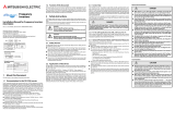
CARLO GAVAZZI RVLFA320040A Manuel utilisateur
- Taper
- Manuel utilisateur

Specications are subject to change without notice. Pictures are just an example. For special features and/or customization, please ask to our sales network. 12/10/2018 1
CARLO GAVAZZI
Automation Components
Motor Controllers AC Variable Frequency Drives
Type VariFlex
3
RVLF

2 Specications are subject to change without notice. Pictures are just an example. For special features and/or customization, please ask to our sales network. 12/10/2018
Motor Controllers AC Variable Frequency Drives Type VariFlex
3
RVLF
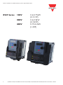
RVLF Series 100V 0.4-0.75kW
(0.5-1HP)
200V 0.4-2.2kW
(0.5-3HP)
400V 0.75-2.2kW
(1-3HP)
Specications are subject to change without notice. Pictures are just an example. For special features and/or customization, please ask to our sales network. 12/10/2018

Specications are subject to change without notice. Pictures are just an example. For special features and/or customization, please ask to our sales network. 12/10/2018 3
Motor Controllers AC Variable Frequency Drives Type VariFlex
3
RVLF
0. Preface 3
1. Safety Precautions 4
1.1. Before power UP 4
1.2. During power UP 5
1.3. Before operation 5
1.4. During operation 6
1.5. Inverter disposal 6
2. Part Number Definition 7
2.1. Model part number 7
2.2. Standard product specication 7
3. Environment & Installation 8
3.1. Environment 8
3.2. Installation 9
3.2.1 Installation methods 9
3.2.2 Installation space 12
3.2.3 Derating curve 13
3.2.4 Capacitor reforming guide after long storage 14
3.2.5 Installation instruction with ferrite ring core 14
3.3. Wiring guidelines 14
3.3.1 Main consideration 14
3.3.2 Control cable selection and wiring 16
3.3.3 Wiring and EMC guidelines 17
3.3.4 Failure liability 18
3.3.5 Considerations for peripheral equipment 19
3.3.6 Ground connection 20
3.3.7 Inverter exterior 20
3.4. Specications 21
3.4.1 Inevrter exterior 21
3.4.2 General specications 23
3.5. Standard wiring 25
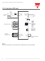
3.5.1 Single phase (NPN input) 25
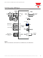
3.5.2 Single phase (PNP input) 26
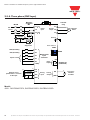
3.5.3 Three phase (NPN input) 27
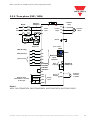
3.5.4 Three phase (PNP input) 28
3.5.5 Three phase (PNP - NPN) 29
3.6. Terminal description 30
3.6.1 Terminal description 30
3.6.2 Control circuit terminal description 31
3.7. Outline dimension 33
3.8. Filter disconnection 36
Index
Specications are subject to change without notice. Pictures are just an example. For special features and/or customization, please ask to our sales network. 12/10/2018

4 Specications are subject to change without notice. Pictures are just an example. For special features and/or customization, please ask to our sales network. 12/10/2018
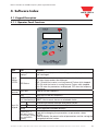
4. Software Index 37
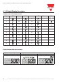
4.1. Keypad description 37
4.1.1 Operator panel functions 37
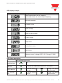
4.1.2 Digital display description 38
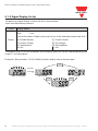
4.1.3 Digital display setup 40
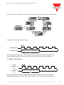
4.1.4 Example of keypad operation 42
4.1.5 Operation control 44
4.2. Programmable parameter groups 45
Annex 1: Consignes de sécurité 59
Motor Controllers AC Variable Frequency Drives Type VariFlex
3
RVLF
Specications are subject to change without notice. Pictures are just an example. For special features and/or customization, please ask to our sales network. 12/10/2018

Specications are subject to change without notice. Pictures are just an example. For special features and/or customization, please ask to our sales network. 12/10/2018 3
Motor Controllers AC Variable Frequency Drives Type VariFlex
3
RVLF
0 Preface
To extend the performance of the product and ensure personnel safety, please read this manual
thoroughly before using the inverter. Should there be any problem in using the product that
cannot be solved with the information provided in the manual, contact our technical or sales
representative who will be willing to help you.
Precautions
The inverter is an electrical product. For your safety, there are symbols such as “Danger”,
“Caution” in this manual as a reminder to pay attention to safety
instructions on handling, installing, operating, and checking the inverter. Be sure to follow the
instructions for highest safety.
Danger Indicates a potential hazard that could cause death or serious personal injury if
misused.
Caution Indicates that the inverter or the mechanical system might be damaged if
misused.
Danger
• Risk of electric shock. The DC link capacitors remain charged for ve minutes after power
has been removed. It is not permissible to open the equipment until 5 minutes after the
power has been removed.
• Do not make any connections when the inverter is powered on. Do not check parts and
signals on circuit boards during the inverter operation.
• Do not disassemble the inverter or modify any internal wires, circuits, or parts.
• Ensure that the inverter ground terminal is connected correctly.
Caution
• Do not perform a voltage test on parts inside the inverter. High voltage can destroy the
semiconductor components.
• Do not connect T1, T2, and T3 terminals of the inverter to any AC input power supply.
• CMOS ICs on the inverter’s main board are susceptible to static electricity. Do not touch the
main circuit board.

4 Specications are subject to change without notice. Pictures are just an example. For special features and/or customization, please ask to our sales network. 12/10/2018
Motor Controllers AC Variable Frequency Drives Type VariFlex
3
RVLF
1.1. Before Power Up
1. Safety Precautions
Danger Make sure the main circuit connections are correct. Single phase L1 (L), L3 (N),
and Three phase L1(L), L2, L3 (N); 400V: L1, L2, L3 are power-input terminals and
must not be mistaken for T1, T2 and T3. Otherwise, inverter damage can result.
Caution
• The line voltage applied must comply with the inverter’s specified input voltage.
(See the nameplate).
• To avoid the front cover from disengaging, or other damge do not carry the inverter
by its covers. Support the drive by the heat sink when transporting.
Improper handling can damage the inverter or injure personnel and should be
avoided.
• To avoid the risk of fire, do not install the inverter on a flammable object. Install on
nonflammable objects such as metal.
• If several inverters are placed in the same control panel, provide heat removal means
to maintain the temperature below 50°C to avoid overheat or fire.
• When disconnecting the remote keypad, turn the power off first to avoid any damage
to the keypad or the inverter.
Warning
• This product is sold subject to EN 61800-3 and EN 61800-5-1.
In a domestic environment this product may cause radio interference in which case
the user may be required to apply corrective measures.
• Motor over temperature protection is not provided.
Caution
• Work on the device/system by unqualified personnel or failure to comply with
warnings can result in severe personal injury or serious damage to material.
Only suitably qualified personnel trained in the setup, installation, commissioning
and operation of the product should carry out work on the device/system.
• Only permanently-wired input power connections are allowed.

Specications are subject to change without notice. Pictures are just an example. For special features and/or customization, please ask to our sales network. 12/10/2018 5
Motor Controllers AC Variable Frequency Drives Type VariFlex
3
RVLF
1.2. During Power Up
1.3. Before Operation
Danger When the momentary power loss is longer than 2 seconds, the inverter will not have
sufcient stored power for its control circuit. Therefore, when the power is re-applied,
the run operation of the inverter will be based on the setup of following parameters:
• Run parameters. 00-02 or 00-03.
• Direct run on power up. Parameter. 07-04 and the status of external run switch,
Note:
The start operation will be regardless of the settings for parameters 07-00/07-01/07-02.
Danger. Direct run on power up.
If direct run on power up is enabled and inverter is set to external run with the run
FWD/REV switch closed then the inverter will restart
Danger
Prior to use, ensure that all risks and safety implications are considered.
• When the momentary power loss ride through is selected and the power loss is
short, the inverter will have sufficient stored power for its control circuits to
function, therefore,when the power is resumed the inverter will automatically
restart depending on the setup of parameters 07-00 & 07-01.
Caution Make sure the model and inverter capacity are the same as that set in parameter
13-00.
Note:
On power up the supply voltage set in parameter 01-01 will flash on display for 2
seconds.

6 Specications are subject to change without notice. Pictures are just an example. For special features and/or customization, please ask to our sales network. 12/10/2018
Motor Controllers AC Variable Frequency Drives Type VariFlex
3
RVLF
1.4. During Operation
Danger Do not connect or disconnect the motor during operation. Otherwise, It may cause
the inverter to trip or damage the unit.
Danger
• To avoid electric shock, do not take the front cover off while power is on.
• The motor will restart automatically after stop when auto-restart function is enabled.
In this case, care must be taken while working around the drive and associated
equipment.
• The operation of the stop switch is different than that of the emergency stop switch.
The stop switch has to be activated to be effective. Emergency stop has to be de
activated to become effective.
Caution
• Do not touch heat radiating components such as heat sinks and brake resistors.
• The inverter can drive the motor from low speed to high speed. Verify the allowable
speed ranges of the motor and the associated machinery.
• Note the settings related to the braking unit.
• Risk of electric shock. The DC link capacitors remain charged for five minutes after
power has been removed. It is not permissible to open the equipment until 5 minutes
after the power has been removed.
Caution
• The Inverter should be used in environments with temperature range from
(14 to +104°F) or (-10 to +40°C) and relative humidity of 95%.
Danger
• Make sure that the power is switched off before disassembling or checking any
components.
1.5. Inverter Disposal
Caution
Please dispose of this unit with care as an industrial waste and according to
your required local regulations.
• The capacitors of inverter main circuit and printed circuit board are considered as
hazardous waste and must not be burnt.
• The plastic enclosure and parts of the inverter such as the cover board will release
harmful gases if burnt.
WEEE designation
Do not dispose of the product together with the household waste but according to the
disposal regulations for electronic waste locally applicable at the product installation site.

Specications are subject to change without notice. Pictures are just an example. For special features and/or customization, please ask to our sales network. 12/10/2018 7
Motor Controllers AC Variable Frequency Drives Type VariFlex
3
RVLF
2.1. Model Part Number
2. Part Number Definition
Ordering Key
VariFlex
3
AC Drive
Frame Size A/B
AC Supply Phase 1/3
Drive Voltage Rating
Drive kW Rating
Filter
Advance
RVLF A 1 20 075 F A
Short circuit capacity is below 5000A/120V or 5000A/240V or 5000A/480V, for 100~120V models is 120V;
200-240V models is 240V, 380-480V for 480V.
Frame Size AC Supply Phase Drive Voltage Rating Drive kW Rating
A: Size 1
B: Size 2
1: 1-Phase
3: 3-Phase
10: 100-120VAC
20: 200-240VAC
40: 380-480VAC
040: 0.40kW, 0.50HP
075: 0.75kW, 1.0HP
150: 1.5kW, 2.0HP
220: 2.2kW, 3.0HP
370: 3.7KW, 5.0HP
550: 5.5KW, 8.0HP
750: 7.5KW, 10HP
1100: 11KW, 15HP
Filter Advance
Nil: No inbuilt Filter
F: Inbuilt lter
A: Advance.
Sensorless vector
control
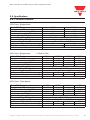
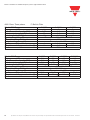
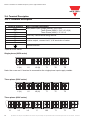
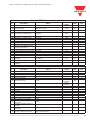
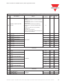
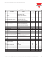
2.2. Standard Product Specification
Model
Supply
Voltage (Vac)
Frequency
(Hz)
(HP) (KW) Filter S LV
RVLFA110040A
1Ph,
100-120V
+10%/-15%
50/60Hz
0.5 0.4
•
RVLFA110075A 1 0.75
•
RVLFA120040FA
1Ph,
200-240V
+10%/-15%
0.5 0.4
• •
RVLFA120075FA 1 0.75
• •
RVLFB120150FA 2 1.5
• •
RVLFB120220FA 3 2.2
• •
RVLFA320040A
3Ph,
200-240V
+10%/-15%
0.5 0.4
•
RVLFA320075A 1 0.75
•
RVLFB320150A 2 1.5
•
RVLFB320220A 3 2.2
•
RVLFB340075FA
3Ph,
380-480V
+10%/-15%
1 0.75
• •
RVLFB340150FA 2 1.5
• •
RVLFB340220FA 3 2.2
• •
RVLFC340370FA
5 3.7
• •
RVLFC340550FA
8 5.5
• •
RVLFD340750FA
10 7.5
• •
RVLFD3401100FA
15 11
• •

8 Specications are subject to change without notice. Pictures are just an example. For special features and/or customization, please ask to our sales network. 12/10/2018
Motor Controllers AC Variable Frequency Drives Type VariFlex
3
RVLF
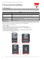
3.1. Environment
3. Environment & Installation
Installation environment has a direct affect on the correct operation and the life expectancy
of the inverter, Install the inverter in an environment complying with the following conditions:
Installation site
Install in an environment that will not have an adverse effect on the operation of the unit and
ensure that there is no exposure to areas such as that listed below:
• Direct sunlight, rain or moisture
• Oil mist and salt
• Dust, lint bbers, small metal lings and corrosive liquid and gas
• Electromagnetic interference from sources such as welding equipment
• Radioactive and ammable materials
• Excessive vibration from machines such as stamping, punching machines
• Add a vibration-proof pads if necessary
Protection
Protection class IP20, NEMA/UL Open Type
Suitable environment
Operating temperature
-10~+40°C (-10~+50°C with fan)
If several inverters are installed in the same control panel, ensure adequate spacing and
provide the necessary cooling and ventilation for successful operation.
Storage temperature -20~+60°C
Relative humidity
Max 95% (without condensation)
Notice prevention of inverter freezing up.
Shock and Vibration
0.075mm Amplitude for 10Hz to 57Hz
1G for 57Hz to 150Hz
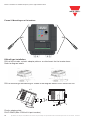
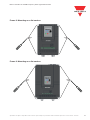
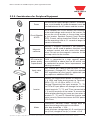
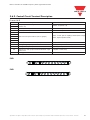
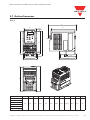
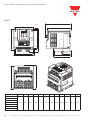
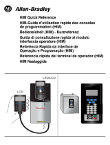
Product Overview
Frame A Frame B
Frame CFrame D
RS485
port
Operator
Panel
TM2
terminal
TM1
terminal
Ground
terminal
Operator
Panel
RS485
port
TM2
terminal
TM1
terminal
Ground
terminal
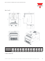
Product Overview
Frame A Frame B
Frame CFrame D
RS485
port
Operator
Panel
TM2
terminal
TM1
terminal
Ground
terminal
Operator
Panel
RS485
port
TM2
terminal
TM1
terminal
Ground
terminal

Specications are subject to change without notice. Pictures are just an example. For special features and/or customization, please ask to our sales network. 12/10/2018 9
Motor Controllers AC Variable Frequency Drives Type VariFlex
3
RVLF
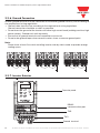
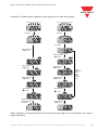
3.2.1. Installation methods
3.2. Installation
Frame1. Mounting on a flat surface.
Note:
RVLF-DIN-01 (Size 1 din rail kit part number), including the following parts
1. Metal plate adaptor
2. Plastic adaptor
3. Chamfer head screw: M3×6
DIN rail type installation:
DIN rail kit includes a plastic and a metal adaptor plates.
Assembly Steps:
1) Attach the metal adaptor plate to the inverter base with the screws provided.
2) Attach the plastic din rail adaptor to the metal adaptor plate.
3) Push the plastic adaptor forward to lock into position.
Disassembly Steps:
1) Unlock by pushing the snap hooks
2) Retract and remove the plastic DIN rail adaptor.
3) Unscrew the metal plate & remove
FUNREVFWDHa/RPM
Freq. Set
MODE
<
ENT
RUN
STOP
RESET
RVLF

10 Specications are subject to change without notice. Pictures are just an example. For special features and/or customization, please ask to our sales network. 12/10/2018
Motor Controllers AC Variable Frequency Drives Type VariFlex
3
RVLF
Frame 2. Mounting on a flat surface.
DIN rail type installation:
DIN rail kit includes a plastic adaptor plate as an attachment for the inverter base.
Refer to diagram below:
DIN rail mounting & dismounting as shown in the diagram below: Use a 35mm DIN rail.
Plastic adaptor plate.
RVLF-DIN02 (Size 2 DIN rail kit part number)
CLICK
1
1
2
2

Specications are subject to change without notice. Pictures are just an example. For special features and/or customization, please ask to our sales network. 12/10/2018 11
Frame 3. Mounting on a flat surface.
Frame 3. Mounting on a flat surface.
Motor Controllers AC Variable Frequency Drives Type VariFlex
3
RVLF

12 Specications are subject to change without notice. Pictures are just an example. For special features and/or customization, please ask to our sales network. 12/10/2018
Motor Controllers AC Variable Frequency Drives Type VariFlex
3
RVLF
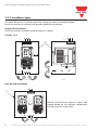
Provide sufcient air circulation space for cooling as shown in examples below.
Install the Inverter on surfaces that provide good heat dissipation.
Single unit Installation
Install the inverter verticality to obtain effective cooling
Frames 1 & 2.
Provide the necessary physical space and
cooling based on the ambient temperature
and the heat loss in the panel.
Side by side Installation
3.2.2. Installation Space
Control
Panel
Fan
12cm
12cm
Front view Side view
5cm
5cm
5cm
Fan
Control
Panel
Control
Panel
Fan
12cm
12cm
Front view Side view
5cm
5cm
5cm
Fan
Control
Panel

Specications are subject to change without notice. Pictures are just an example. For special features and/or customization, please ask to our sales network. 12/10/2018 13
Motor Controllers AC Variable Frequency Drives Type VariFlex
3
RVLF
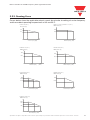
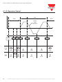
Curves below show the applicable output current de-rate due to setting of carrier frequency
and the ambient operating temperatures of 40 and 50°C.
3.2.3. Derating Curve
100%
80%
5 16
Rated Current (In)
Carrier Frequency (kHz)
100%
90%
10
16
Rated Current (In)
Carrier Frequency (kHz )
100 %
90 %
10 K
16 K
Rated Current ( In)
Carrier Frequency (KHz )
100%
87%
10
16
Rated Current (In )
Carrier Frequency (kHz )
100%
84.6%
61.5%
5 10 16
Rated Current (In)
Carrier Frequency (kHz)
100%
60.6%
8 16
Rated Current (In)
Carrier Frequency (kHz )
100%
70%
55%
5 10 16
Rated Current (In)
Carrier Frequency (kHz )
RVLFA*2**FA (40°C) RVLFA1100**A (40°C), RVLFB*2****A (50°C)
RVLFB340***FA (50°C) RVLFC340370FA (50°C)
RVLFC340550FA (50°C)
RVLFD3401100FA (50°C)
RVLFD340750FA (50°C)

14 Specications are subject to change without notice. Pictures are just an example. For special features and/or customization, please ask to our sales network. 12/10/2018
Motor Controllers AC Variable Frequency Drives Type VariFlex
3
RVLF
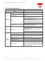
For correct performance of this product after long storage before use it is important that Inverter
Capacitors are reformed according to the guide below:
Note 1: Rated voltage: please refer the rated voltage according to model label of inverter.
3.2.4 Capacitor reforming guide after long storage
Storage time Procedure to re-apply voltage
≤ 1year Apply rated voltage(Note1) of inverter in the normal way
Between 1-2 years
Apply rated voltage of inverter to the product for one hour before using
the inverter
≥ 2 years
Use a variable AC power supply to
1.Connecting 25% rated voltage of inverter for 30 minutes.
2.Connecting 50% rated voltage of inverter for 30 minutes.
3.Connecting 75% rated voltage of inverter for 30 minutes.
4.Connecting 100% rated voltage of inverter for 210 minutes. Once
the procedures completed, inverter just can be used normally.
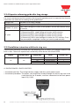
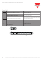
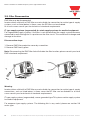
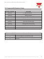
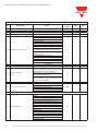
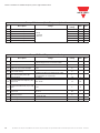
3.2.5 Installation instruction with ferrite ring core
Ferrite cores should be installed with the following units to reduce the leakage current in the
built-in lter. These will improve the functionality of the drives with 30mA RCDs.
Supply Voltage (VAC) Rating (kW) Drive Ferrite core
1-Ph 200
0.40 RVLFA120040FA 1
0.75 RVLFA120075FA 1
1.50 RVLFB120150FA 2
2.20 RVLFB120220FA 2
Installation diagrams:
A. RVLFA120040FA / RVLFA120075FA
• Installation position: The wiring between supply and drive (main power input).
• Installation procedure: The power cord should be winded through the ferrite ring core in the
same direction for 3 rounds; and then connected to the main power
input L1(L) L3(N).

Specications are subject to change without notice. Pictures are just an example. For special features and/or customization, please ask to our sales network. 12/10/2018 15
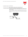
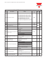
B. RVLFB120150FA / RVLFB120220FA
• Installation position: The wiring between supply and drive (main power input).
The wiring between earth and drive (ground terminal).
• Installation procedure: The power cord should be winded through the ferrite ring core in the
same direction for 2 rounds; and then connected to the main power
input L1(L) L3(N).
The earth conductor should be winded through the ferrite ring core
in the same direction for 3 rounds; and then connected to the ground
terminal.
Motor Controllers AC Variable Frequency Drives Type VariFlex
3
RVLF

16 Specications are subject to change without notice. Pictures are just an example. For special features and/or customization, please ask to our sales network. 12/10/2018
Motor Controllers AC Variable Frequency Drives Type VariFlex
3
RVLF
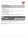
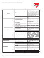
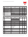
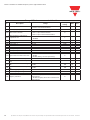
3.3.1. Main Considerations
3.3. Wiring Guidelines
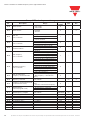
1. Tightening Torque for Screw terminals : Refer to the tables 3-1, when using a screwdriver or
any other suitable tools to make connections.
2. Power terminals:
Single phase : L1 (L), L3 (N)
Three-phase 200V models: L1 (L), L2, L3 (N)
400V models: L1, L2, L3
3. For all cabling use copper wires and the cable size shall be according to the table below
rated at 105 degrees Celsius.
4. Power & Control cable Minimum rated voltage
240V AC system, 300V AC.
480V AC system, 600V AC.
5. Control cables should be separated from the power cables. Do not place them in the same
cable tray or cable trunking to prevent against electrical interference.
Frame size
TM1 TM1/TM2
Cable Size Tightening torque Cable Size Tightening torque
AWG mm² kgf.cm Ibf.in Nm AWG mm² kgf.cm Ibf.in Nm
Frame A
22~10 0.34~6
14 12.15 1.37
24~12 0.5~2.5 4.08 3.54 0.4
Frame B 12.24 10.62 1.2
Frame C 18~8 0.82~8.4 18 15.58 1.76
24~12 0.5~2.5 5.1 4.43 0.5
Frame D 14~6 2~13.3 24.48 21.24 2.4
Supply power cable must be connected to TM1 terminal block, terminals L1 (L) and L3 (N) for
single phase 200V supply, L1 (L), L2, L3 (N) and L1, L2, L3 for three phase 400V supply.
Motor cable must be connected to TM1 terminals. T1, T2, T3.
Warning: Connection of supply line cable to terminals T1, T2 & T3 will result in serious damage
to the drive components.

Specications are subject to change without notice. Pictures are just an example. For special features and/or customization, please ask to our sales network. 12/10/2018 17
Motor Controllers AC Variable Frequency Drives Type VariFlex
3
RVLF
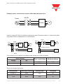
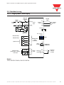
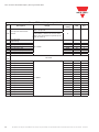
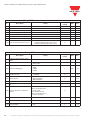
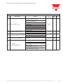
Example power connections: inverter with dedicated power line.
Install a supply RFI lter or Isolation transformer when the power source is shared with other
high power electrical equipment as shown below.
Inverter IM
Power
MCCB
Inverter IM
Machine
RFI
Filter
Power
MCCB
Inverter IM
Machine
Insulation transformer
Power
MCCB
The maximum rms symmetrical amperes and voltage are listed as follows
Electrical ratings of terminals
Inverter IM
Power
MCCB
Inverter IM
Machine
RFI
Filter
Power
MCCB
Inverter IM
Machine
Insulation transformer
Power
MCCB
Inverter IM
Power
MCCB
Inverter IM
Machine
RFI
Filter
Power
MCCB
Inverter IM
Machine
Insulation transformer
Power
MCCB
Device Rating
Short circuit Rating Maximum Voltage
Voltage HP
220V 0.2~3 5000A 240V
440V 1~3 5000A 480V
Horse power Power Specification Voltage (Volt) Current(A)
0.25/0.5/1 220V
300
30
2/3 220V 30
1/2/3 440V 600 28

18 Specications are subject to change without notice. Pictures are just an example. For special features and/or customization, please ask to our sales network. 12/10/2018
Motor Controllers AC Variable Frequency Drives Type VariFlex
3
RVLF
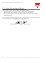
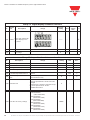
Connect the shield to
inverter ground terminal
Do not connect this end
Protective coveringShielding sheath
3.3.2. Control Cable selection and Wiring
Control cables should be connected to terminal block TM2.
Choose power & control cables according to the following criteria:
• Use copper wires with correct diameter and temperature rating of 60/75°C.
• Minimum cable voltage rating for 200V type inverters should be 300VAC.
• Route all cables away from other high voltage or high current power lines to reduce
interference effects.
Use a twisted pair shielded cable and connect the shield (screen) wire to the ground terminal
at the inverter end only. Cable length should not exceed 50 meters.
La page est en cours de chargement...
La page est en cours de chargement...
La page est en cours de chargement...
La page est en cours de chargement...
La page est en cours de chargement...
La page est en cours de chargement...
La page est en cours de chargement...
La page est en cours de chargement...
La page est en cours de chargement...
La page est en cours de chargement...
La page est en cours de chargement...
La page est en cours de chargement...
La page est en cours de chargement...
La page est en cours de chargement...
La page est en cours de chargement...
La page est en cours de chargement...
La page est en cours de chargement...
La page est en cours de chargement...
La page est en cours de chargement...
La page est en cours de chargement...
La page est en cours de chargement...
La page est en cours de chargement...
La page est en cours de chargement...
La page est en cours de chargement...
La page est en cours de chargement...
La page est en cours de chargement...
La page est en cours de chargement...
La page est en cours de chargement...
La page est en cours de chargement...
La page est en cours de chargement...
La page est en cours de chargement...
La page est en cours de chargement...
La page est en cours de chargement...
La page est en cours de chargement...
La page est en cours de chargement...
La page est en cours de chargement...
La page est en cours de chargement...
La page est en cours de chargement...
La page est en cours de chargement...
La page est en cours de chargement...
La page est en cours de chargement...
La page est en cours de chargement...
La page est en cours de chargement...
La page est en cours de chargement...
La page est en cours de chargement...
La page est en cours de chargement...
-
 1
1
-
 2
2
-
 3
3
-
 4
4
-
 5
5
-
 6
6
-
 7
7
-
 8
8
-
 9
9
-
 10
10
-
 11
11
-
 12
12
-
 13
13
-
 14
14
-
 15
15
-
 16
16
-
 17
17
-
 18
18
-
 19
19
-
 20
20
-
 21
21
-
 22
22
-
 23
23
-
 24
24
-
 25
25
-
 26
26
-
 27
27
-
 28
28
-
 29
29
-
 30
30
-
 31
31
-
 32
32
-
 33
33
-
 34
34
-
 35
35
-
 36
36
-
 37
37
-
 38
38
-
 39
39
-
 40
40
-
 41
41
-
 42
42
-
 43
43
-
 44
44
-
 45
45
-
 46
46
-
 47
47
-
 48
48
-
 49
49
-
 50
50
-
 51
51
-
 52
52
-
 53
53
-
 54
54
-
 55
55
-
 56
56
-
 57
57
-
 58
58
-
 59
59
-
 60
60
-
 61
61
-
 62
62
-
 63
63
-
 64
64
-
 65
65
-
 66
66


CARLO GAVAZZI RVLFA320040A Manuel utilisateur
- Taper
- Manuel utilisateur
dans d''autres langues
Documents connexes
Autres documents
-
LG ATNW36GMLS1.ENWTMEA Guide d'installation
-
EEMB ER14505 Fiche technique
-
Emotron DSV15-35 Mounting Instruction
-
Omron CIMR-J7AZ Le manuel du propriétaire
-
 Z-BEN D700 Series Guide d'installation
-
ICP I-8024W Manuel utilisateur
-
Eaton PowerXL DH1 Guide d'installation
-
Husqvarna PG 530 Le manuel du propriétaire
-
 Allen-Bradley 22HIM-QR001 Guide de référence
-
Airwell PAC BT Series Guide d'installation

