
Outdoor Refrigerator / Freezer
Réfrigérateur / Congélateurs
d'extérieur
Refrigeradores / Congeladors
exterior
MO24RF
EN Installation, Operation and Maintenance Instructions
FR Instructions d’installation, d’utilisation et d’entretien
ES Instrucciones de instalación, operación y mantenimiento

2
NOTE
!
CAUTION
Important Safety Instructions
Warnings and safety instructions appearing in this guide
are not meant to cover all possible conditions and situa-
tions that may occur. Common sense, caution, and care
must be exercised when installing, maintaining, or operat-
ing this appliance.
Recognize Safety Symbols,
Words, and Labels.
CAUTION-Hazards or unsafe practices which could re-
sult in personal injury or property / product damage.
NOTE-Important information to help assure a problem
free installation and operation.
is committed to building a quality product
in an environmentally friendly manner. Our processes are
tightly controlled and closely monitored. We have achieved
certications in ISO 9001 for quality assurance, ISO 14001
for environmental management, and OHSAS 18001 for oc-
cupational health and safety from Lloyd’s Register Quality
Assurance.
CONTENTS
Contents:
Safety information ...............................................................2
Unpacking your appliance ..................................................3
Warranty registration ......................................................3
Installing your appliance ......................................................4
Cabinet clearances .........................................................4
Leveling the appliance ....................................................4
Electrical connection ......................................................5
Installing the water supply ...................................................6
Optional ice-maker operation ..............................................7
Installing the anti-tip device .................................................8
Product dimensions ..........................................................10
Starting your appliance ..................................................12
Using your Electronic control ............................................12
Sleep mode ...................................................................12
Turning your appliance "ON" or "OFF" ..........................13
Adjusting the temperature .............................................13
Temperature mode ........................................................13
Control lock ................................................................14
Temperature sensor error codes ................................14
Alarms ...........................................................................14
Door ajar ..................................................................14
Power failure .............................................................15
Temperature alarm ....................................................15
Vacation mode ..................................................................15
Shelving congurations ....................................................16
Shelf removal ...................................................................17
Care and cleaning .............................................................18
Long term storage/winterization ...................................18
Stainless steel maintenance .............................................22
Energy saving tips ............................................................22
Obtaining service .............................................................23
Troubleshooting .................................................................24
Troubleshooting ice-maker ..............................................25
Warranty ...........................................................................26
!
WARNING
WARNING - You can be killed or seriously injured
if you do not follow these instructions.
!
WARNING
State of California Proposition 65 Warning:
This product contains one or more chemicals known
to the State of California to cause cancer.
!
WARNING
State of California Proposition 65 Warning:
This product contains one or more chemicals known
to the State of California to cause birth defects or
other reproductive harm..
Death or serious injury could result if...

3
NOTE
!
CAUTION
XXXXXXXXXXXX
XXXXXXXXXXXX
!
WARNING
EXCESSIVE WEIGHT HAZARD
Use two or more people to move product.
Failure to do so can result in personal injury.
Remove Interior Packaging
Your appliance has been packed for shipment with all parts
that could be damaged by movement securely fastened.
Remove internal packing materials and any tape holding in-
ternal components in place. The owners manual is shipped
inside the product in a plastic bag along with the warranty
registration card, and other accessory items.
Important
Keep your carton and packaging until your appliance has
been thoroughly inspected and found to be in good condi-
tion. If there is damage, the packaging will be needed as
proof of damage in transit. Afterwards please dispose of all
items responsibly.
Note to Customer
This merchandise was carefully packed and thoroughly
inspected before leaving our plant. Responsibility for its
safe delivery was assumed by the retailer upon acceptance
of the shipment. Claims for loss or damage sustained in
transit must be made to the retailer.
DO NOT RETURN DAMAGED MERCHANDISE TO THE
MANUFACTURER - FILE THE CLAIM WITH THE
RETAILER.
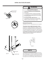
If the appliance was shipped, handled, or stored in other
than an upright position for any period of time, allow the ap-
pliance to sit upright for a period of at least 24 hours before
plugging in. This will assure oil returns to the compressor.
Plugging the appliance in immediately may cause damage
to internal parts.
Warranty Registration
UNPACKING YOUR APPLIANCE
Online registration
available at
www.agamarvel.com
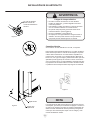
It is important you send in your warranty registration card
immediately after taking delivery of your appliance or you
can register online at www.agamarvel.com.
The following information will
be required when registering
your appliance.
Service Number
Serial Number
Date of Purchase
Dealer’s name and address
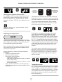
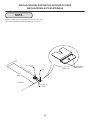
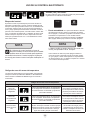
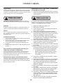
The service number and serial number can be found on the
serial plate which is located inside the cabinet on the right
side near the top. (See gure 1).
Figure 1
!
WARNING
WARNING - Help Prevent Tragedies
Child entrapment and suffocation are not problems of
the past. Junked or abandoned refrigerators are still
dangerous - even if they sit out for "just a few hours".
If you are getting rid of your old refrigerator, please
follow the instructions below to help prevent acci-
dents.
Before you throw away your old refrigerator or
freezer:
• Take off the doors or remove the drawers.
• Leave the shelves in place so children may not
easily climb inside.
!
WARNING
WARNING - Dispose of the plastic bags which can
be a suffocation hazard.

4
!
CAUTION
INSTALLING YOUR APPLIANCE
Select Location
The proper location will ensure peak performance of your
appliance. We recommend a location where the unit will
be out of direct sunlight and away from heat sources. To
ensure your product performs to specications, the recom-
mended installation location temperature range is from 55
to 115°F (13 to 46°C).
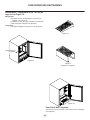
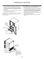
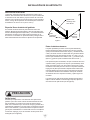
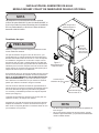
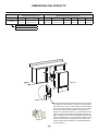
Cabinet Clearance
Ventilation is required from the bottom front of the appli-
ance. Keep this area open and clear of any obstructions.
Adjacent cabinets and counter top can be installed around
the appliance as long as the front grille remains unobstruct-
ed.
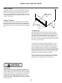
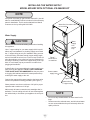
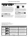
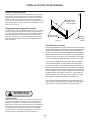
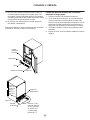
Front Grille
Do not obstruct the front grille. The openings within the
front grille allow air to ow through the condenser heat ex-
changer. Restrictions to this air ow will result in increased
energy usage and loss of cooling capacity. For this reason
it is important this area not be obstructed and the grille
openings kept clean. AGA MARVEL does not recommend
the use of a custom made grille as air ow may be restrict-
ed. (See Figure 2).
Rear
Leveling
Legs
Figure 2
Front Leveling
Legs
Front Grille,
keep this area
open.
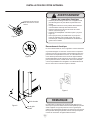
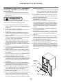
Leveling Legs
Adjustable legs at the front and rear corners of the appli-
ance should be set so the unit is rmly positioned on the
oor and level from side to side and front to back. The over-
all height of your Marvel appliance may be adjusted be-
tween the minimum, 33
3
⁄4" (85.7 cm), by turning the leveling
leg in (CW ↷) and the maximum, 34
3
⁄4" (88.3 cm) by turning
the leveling leg out (CCW ↶).
To adjust the leveling legs, place the appliance on a solid
surface and protect the oor beneath the legs to avoid
scratching the oor. With the assistance of another person,
lean the appliance back to access the front leveling legs.
Raise or lower the legs to the required dimension by turning
the legs. Repeat this process for the rear by tilting the appli-
ance forward using caution. On a level surface check the
appliance for levelness and adjust accordingly.
The front grille screws may be loosened and the grille ad-
justed to the desired height. When adjustment is complete
tighten the two front grille screws. (See Figure 5).

5
NOTE
Figure 3
Figure 4
Do not remove
ground prong
INSTALLING YOUR APPLIANCE
Front grille
Front grille screw
Figure 5
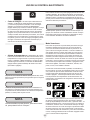
Electrical Shock Hazard
• Do not use an extension cord with this appliance.
They can be hazardous and can degrade product
performance.
• This appliance should not, under any circumstanc-
es, be installed to an un-grounded electrical supply.
• Do not remove the grounding prong from the power
cord. (See Figure 3).
• Do not use an adapter. (See Figure 4).
• Do not splash or spray water from a hose on the
appliance. Doing so may cause an electrical shock,
which may result in severe injury or death.
!
WARNING
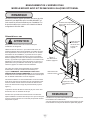
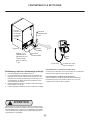
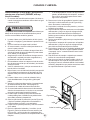
Electrical Connection
A grounded 115 volt, 15 amp dedicated circuit is required.
This product is factory equipped with a power supply
cord that has a three-pronged, grounded plug. It must be
plugged into a mating grounding type receptacle in accor-
dance with the National Electrical Code and applicable lo-
cal codes and ordinances (see Figure 6). If the circuit does
not have a grounding type receptacle, it is the responsibility
and obligation of the customer to provide the proper power
supply. The third ground prong should not, under any cir-
cumstances, be cut or removed.
Figure 6
Ground Fault Circuit Interrupters (GFCI) are prone to nui-
sance tripping which will cause the appliance to shut down.
GFCI’s are generally not used on circuits with power equip-
ment that must run unattended for long periods of time, un-
less required to meet local building codes and ordinances.

6
Figure 7a
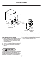
• Do not use any thread sealers on these water line t-
tings.
• Reverse osmosis, softened water, and de-ionized water
are not recommended as they will adversely affect the
quality of the ice.
Water
Supply
Line
service
loop
Figure 7
Back view of
ice machine
NOTE
NOTE
!
CAUTION
Water line from water valve
to ice-maker
INSTALLING THE WATER SUPPLY
MODEL MO24RF WITH OPTIONAL ICE-MAKER KIT
An optional ice-maker kit (part number S42418151) is avail-
able for model MO24RF which includes all of the necessary
parts for installation. The kit can be obtained from Marvel
customer service by calling 800-223-3900.
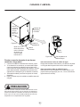
Water Supply
Observe and follow all local building codes when installing
this appliance.
Use
1
⁄4" copper tubing for your water supply which is avail-
able at any local hardware or plumbing supply store. Bend
the
1
⁄4" copper tubing to suit your installation being sure not
to kink the tubing. Purchase enough copper tubing length
and coil it behind the unit to form a "service loop" which will
allow the appliance to be pulled out from the installation for
servicing or cleaning. Connect the copper tubing to the "top
side" of a cold water pipe to prevent the ice-maker from
plugging with sediment.
A shutoff valve is recommended on the water supply line to
ease servicing the appliance. NOTE: A SELF-PIERCING
TYPE VALVE IS NOT RECOMMENDED as they are prone
to clogging with sediment which will create pressure drop
reducing the water supply to the unit.
Connect the copper tubing water supply to the brass union
with the compression nut tting provided. (See Figure 7).
Water pressure must be at a minimum of 20 psi for proper
operation and a maximum of 120 psi.
Make certain all water connections are watertight after in-
stallation. Form the tubing so that it will not vibrate against
the cabinet body or kink when your appliance is set in posi-
tion.
Brass union for
1
⁄4" copper tubing
Connect water
supply here

7
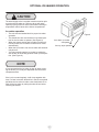
NOTE
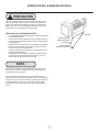
Ice-maker operation
• The unit must be installed level for proper ice-maker
operation.
• The shutoff arm wire must be down in its lowest posi-
tion for the ice-maker to operate. (See Figure 8).
• When the freezer section and ice-maker unit has suf-
ciently cooled, the ice-maker will harvest ice cubes
automatically.
• When the ice bucket is full, the ice-maker will automati-
cally shut off.
• You may manually stop the ice-maker by raising the
shut off arm to the locking position at the up most posi-
tion. (See Figure 8).
Arm down, ice-maker
will operate
Arm up, stops operation
Figure 8
OPTIONAL ICE-MAKER OPERATION
!
CAUTION
The water supply to the ice-maker must be turned on prior
to turning the ice-maker on. Failure to do so will cause
rapid dry cycling of the ice-maker mold heater resulting in
temperature control issues in the freezer compartment.
It is recommended the ice-maker is shut off when remov-
ing the bucket, or ice may be dispensed onto the freezer
compartment oor.
If the ice is not used regularly, it will clump together with
time. For best ice results, discard ice in the bin as required
and allow the ice-maker to make a new fresh batch of ice.
Shut-off the ice-maker by raising the shut-off arm before
removing the bucket.

8
!
CAUTION
NOTE
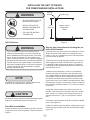
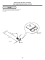
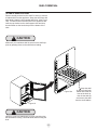
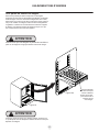
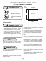
INSTALLING THE ANTI TIP DEVICE
FOR FREESTANDING INSTALLATIONS
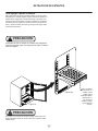
Step by step instructions for locating the po-
sition of the bracket:
1) Decide where you want to place the refrigerator / freezer.
Slide it into place, being careful not to damage the oor,
leaving 1" (2.5 cm) of clearance from the rear wall to allow
room for the anti-tip bracket.
2) Raise the rear leveling legs approximately
1
⁄4" (6 mm) to
allow engagement with the anti-tip bracket. Level the unit
by adjusting all the leveling legs as required. Turning the
leveling leg counterclockwise will raise the unit and clock-
wise will lower the unit.
3) Make sure the refrigerator / freezer is in the desired
location, then mark on the oor the rear and side corner
of the cabinet where the anti-tip bracket will be installed. If
the installation does not allow marking the rear corner of
the cabinet, then make temporary lines on the oor mark-
ing the front corner of the cabinet, excluding the door. Slide
the refrigerator / freezer out of the way. From the temporary
line extend the sidewall line back 21
1
⁄2" (54.6 cm) as shown
in Figure 10.
4) Align the anti-tip bracket to the marks on the oor so
the side of the bracket lines up with the side of the cabinet
mark, and the "V" notches on the anti-tip bracket line up
with the end of the 21
1
⁄2" (54.6 cm) line (Rear of cabinet
line).
5) Fasten the anti-tip bracket to the oor using the supplied
screw. (See Figure 10).
6) Slide the cabinet back into position, making sure the rear
cabinet leveling leg slides under the anti-tip bracket engag-
ing the slot.
Front of cabinet
Figure 9
21
1
⁄2"
(54.6 cm)
Anti-Tip
Bracket
Leveling Leg
Bottom View of
Refrigerator /
freezer
!
WARNING
If your refrigerator / freezer is not located under a
counter top (free standing), you must use an anti-tip
device installed as per these instructions. If the refrig-
erator / freezer is removed from its location for any
reason, make sure that the device is properly engaged
with the anti-tip bracket when you push the refrigerator
/ freezer back into the original location. If the device is
not properly engaged, there is a risk of the refrigerator
/ freezer tipping over, with the potential for property
damage or personal injury.
Floor Mount Installation
The anti-tip bracket is to be located on the oor in the left
or right rear corner of the refrigerator / freezer as shown in
Figure 9.
!
WARNING
• ALL APPLIANCES CAN TIP
RESULTING IN INJURY.
• INSTALL THE ANTI-TIP
BRACKET PACKED WITH
THE APPLIANCE.
• FOLLOW THE INSTRUC-
TIONS BELOW
Anti-Tip Device
If installing on a concrete oor, concrete fasteners are
required, (not included with the anti-tip kit).
Any nished ooring should be protected with appropriate
material to avoid damage when moving the unit.

9
NOTE
INSTALLING THE ANTI TIP DEVICE
FOR FREESTANDING INSTALLATIONS
When the oor mounted anti-tip bracket is used the mini-
mum adjusted height of the cabinet is increased by
3
⁄8" (9 mm).
Figure 10a
"V" notches
in bracket
"V" notches
in bracket
Figure 10
21
1
⁄2"
(54.6 cm)
Front of cabinet line
Rear Leveling leg
Side of cabinet line
Rear of cabinet line
Screw

10
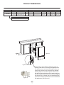
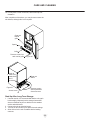
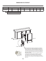
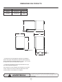
"A"
"B"
"C"
"D"
"E"
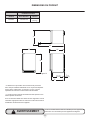
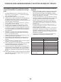
PRODUCT DIMENSIONS
ROUGH-IN OPENING DIMENSIONS CABINET DIMENSIONS
MODEL "A" "B" "C" "D" "E" "F" "G" "H" "J"
MO24RFS
24"
(61 cm)
**34" to 35"
(86.4 to 88.9 cm)
*
23
7
⁄8"
(60.7 cm)
33
3
⁄4" to 34
3
⁄4"
(85.7 to 88.3 cm)
23
23
⁄32"
(60.2 cm)
26
7
⁄32"
(66.6 cm)
46
13
⁄32"
(117.9 cm)
26
1
⁄4"
(66.7 cm)
DOOR STYLE
(S) Solid Door
Figure 11
Figure 11a
Figure 12
If necessary to gain clearance inside the rough-in
opening a hole can be cut through the adjacent cabi-
net and the power cord routed through this hole to a
power outlet. Another way to increase the available
opening depth is to recess the power outlet into the
rear wall to gain the thickness of the power cord plug.
Not all recessed outlet boxes will work for this applica-
tion as they are too narrow, but a recessed outlet box
equivalent to Arlington #DVFR1W is recommended for
this application, (see Figure 12).

11
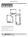
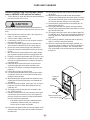
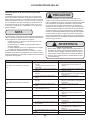
"F"
"D"
"E"
"H"
"J"
"G"
5
⁄8"
(1.6 cm)
PRODUCT DIMENSIONS
PRODUCT DATA
MODEL
ELECTRICAL
REQUIREMENTS #
PRODUCT
WEIGHT
MO24RFS 115V/60Hz/15A
140 lbs
(63.6 kg)
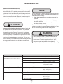
!
WARNING
Floor mount Anti-tip Bracket must be installed for freestand-
ing applications. Not required for built in applications.
* Depth dimension of rough-in opening may vary depending
on each individual installation. To recess entire door "F" di-
mension plus 1" (2.5 cm) for thickness of power cord plug.
** Minimum rough-in opening required is to be larger than
the adjusted height of the cabinet.
# A grounded 15 amp dedicated circuit is required. Follow
all local building codes when installing electrical and appli-
ance.
Figure 13
21
1
⁄2"
(54.6cm)

12
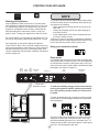
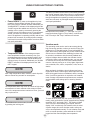
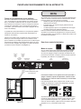
Power Failure
ALARM RESET
Compartment
select
REF
FRZ
Figure 14
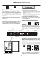
Using your electronic control:
The sleep mode can be disabled if you prefer to have the
display on continuously. Press and hold the "Lock" key-
pad until the display goes past "Loc" and reads "nSL". To
enable the sleep mode, repeat the instruction, again going
past "Loc" until the display reads "SLP".
To wake the display press any keypad. A conrm tone will
sound, and the current storage compartment temperature
will be displayed.
Sleep mode:
If no keypads are pressed for 60 seconds, the display will
enter sleep mode to conserve power. The control panel will
go dark with the exception of the system status "OK" indi-
cator which will remain enabled. Alarm conditions will wake
the display, (see alarms on page 14).
Starting your appliance:
Plug the appliance power cord into a 115 volt wall outlet.
Your appliance is shipped from the factory in the "On" posi-
tion and will begin start-up of cooling as soon as power is
supplied. If the appliance does not start, conrm that the
wall outlet has power, and that the control is in the "On"
position, (See "Turning your appliance On and Off" below).
The control display is covered with a clear plastic lm. This
lm may be removed by carefully lifting the lm at a corner.
On initial power up, the control display will indicate a
"Power Failure" alarm. This is a normal condition as the ap-
pliance was powered-up at the factory for quality inspection
and then removed from power. A momentary press of the
"On/Off" keypad will reset this alarm condition. (See Alarms
section on page 14).
STARTING YOUR APPLIANCE
Figure 14a
Electronic control
Temp
Minus
keypad
Temp
Plus
keypad
On/Off
keypad
Display Area
Lock
keypad
System Status
indicators
NOTE
To make the following changes to the control settings
(turning the appliance ON/OFF, adjusting the tempera-
ture, and activating vacation mode), the control must
be awake.
Your product has an automatic defrost feature that utilizes
an electric heater element. Periodically during defrost you
may observe the following:
• Water dripping and running sounds as a result of the
frost melt
• Sizzling and popping sounds from water dripping on
the heater element
• A faint reddish glow in the freezer compartment from
the electric heater element
These are all “normal” operating characteristics related to
refrigeration product incorporating automatic defrost. They
do not represent any product fault or safety issue.

13
warmer respectively. When you have reached your desired
set-point temperature, press the "On/Off" keypad to accept,
or do nothing and the "Set" mode will time-out in 10-sec-
onds accepting the displayed temperature as the new
set-point.
The available set-point temperature range for your appli-
ance is -6°F (-21°C) to 6°F (-14°C) for the freezer com-
partment (ice-maker) and 34°F (1.2°C) to 42°F (5.7°C) for
the refrigerator compartment. If you attempt to adjust the
temperature outside of these ranges you will receive an
audible notication.
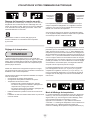
Freezer
compartment
selected
Refrigerator
compartment
selected
REF
FRZ
REF
FRZ
Temperatures can be set for each individual compartment
(refrigerator or freezer / ice-maker). To do so you must rst
select the compartment you want to set the temperature for.
You do so by pressing the refrigerator (REF) or freezer
(FRZ) button on the display. When pressed the LED light
will be illuminated for the respective display.
To change the set temperature for a particular compart-
ment, with the compartment enabled and out of sleep
mode, press the "-" or "+" keypads. "SET" will be indi-
cated on the user interface panel and the current set-point
temperature will display and ash. Subsequent presses of
the "-" or "+" keypads will adjust the temperature colder or
Adjusting the temperature:
When making temperature set-point changes, it may take
up to 24-hours for the stored contents to stabilize at your
new set-point temperature.
Factors that affect the storage compartment stabilized
temperature:
• Changes to temperature setting.
• Room temperature changes.
• Temperature of stored contents.
- Loading warm contents.
- Cold content load will delay the change to a warmer
set-point temperature.
- Warm content load will delay the change to a colder
set-point temperature.
• Usage, (number and duration of the door openings).
• Installation of the appliance in direct sunlight or next to
a heat source.
Turning your appliance ON and OFF:
If the appliance is "On", (and out of sleep mode) the tem-
perature will be shown in the display area of the control.
To turn the appliance "Off", press and hold the "On/Off"
keypad for 4-seconds. "OFF" will now be displayed on the
control.
To turn the appliance "On", press and hold the "On/Off"
keypad for 4-seconds.
USING YOUR ELECTRONIC CONTROL
Temperature mode:
The temperature mode is preset from the factory in Fahren-
heit (°F) but you have the option to change it to Centigrade
(°C). To change the mode, press and hold the "-" keypad,
while pressing the "+" keypad, then release the "-" keypad.
The temperature will now be displayed in Centigrade (°C).
Repeat the procedure to change the temperature mode
back to Fahrenheit (°F).
NOTE
Loading warm contents may trigger a temperature alarm,
see temperature alarm page 15. Depending on the quantity
and/or weight of warm contents, it may take 48 hours for
the compartment temperature to stabilize.

14
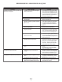
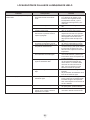
Temperature Sensor Error Codes
Sensor Displayed Code Error Description Action to Take
Refrigerator
Temperature
Sensor
Failed temperature sensor in the
refrigerator compartment. Can lead to
unwanted storage temperatures and/or
spoiled perishable goods.
Call service to have the
temperature sensor replaced and
remove all perishable goods from com-
partment to prevent spoilage.
Freezer
Temperature
Sensor
Failed temperature sensor in the
freezer compartment. Can lead to
unwanted storage temperatures and/or
spoiled perishable goods.
Call service to have the
temperature sensor replaced and
remove all perishable goods from com-
partment to prevent spoilage.
Defrost Sensor
Failed defrost temperature sensor.
Causes unit to not defrost properly and
can create large frost build-up. Can lead
to water damage to the unit and sur-
rounding oor.
Unplug the power cord
immediately and call service to have
the defrost sensor replaced.
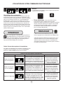
Door Ajar
ALARM RESET
USING YOUR ELECTRONIC CONTROL
Alarms:
The control will alert you to conditions that could adversely
affect the performance of the appliance.
• Door ajar - If the door is open, or not closed prop-
erly, for more than 5-minutes the System Status OK
indicator will turn-off, the "Door Ajar" indicator will ash,
and a tone will sound every 60 seconds. Additionally,
an "ALARM RESET" indicator will be displayed below
the "On/Off" keypad.
The temperature sensors are monitored continuously. Any
OPEN or SHORTED circuit condition will initiate an
ERROR CODE as listed below:
Temperature Sensor Error Codes
Control lock:
The control panel can be locked to avoid unintentional
changes. To lock the control, press and hold the "Lock" key-
pad until the display reads "Loc" then immediately release
your nger from the keypad. The lock icon will ash 3-times
and then continuously illuminate. When the control panel is
locked, only the Lock keypad, System Status OK indicator
, and the Alarm indicator are active. To un-lock the control
panel, repeat this instruction until the display reads "nLc"
then immediately release your nger from the keypad.
NOTE
If the control lock is active (illuminated lock icon) the
control will have to be unlocked before using the
keypad to reset an alarm condition. See page 14
(Control Lock) for instructions for unlocking the control.
This alarm condition can be reset by closing the door or
momentarily pressing the "On/Off" keypad, (i.e.-if you
are cleaning the storage compartment, etc.). The alarm
will recur in 5-minutes if the alarm condition persists.
NOTE
The audible alarm can be muted, for each occurrence,
by pressing the lock keypad.

15
ALARM RESET
Power Failure
ALARM RESET
Temp
NOTE
Door Ajar
Temp
• Power failure - If power to the appliance is inter-
rupted the System Status indicator will turn-off and
the "Power Failure" indicator will ash. Additionally, an
"ALARM RESET" indicator will be displayed below the
"On/Off" keypad. No audible tone will sound. This alarm
condition can be reset by momentarily pressing the
"On/Off" keypad. If this alarm occurs, it is recommend-
ed that you check the condition of any perishables,
even if the appliance is operating normally and the tem-
perature has recovered, as prolonged power outages
could result in excessive temperature excursions which
may spoil perishables.
• Temperature alarm - If the storage compart-
ment temperature deviates excessively from your
set-point temperature for an extended period of time,
the "TEMP" indicator will ash, and an audible tone
will sound every 60 seconds. Additionally, an "ALARM
RESET" indicator will be displayed below the "ON/
OFF" keypad.
Multiple alarms are possible, i.e.- "Door Ajar" for a pro-
longed period may trigger a "Temp" alarm, in which case
both "Door Ajar" and "Temp" indicators will activate.
Vacation mode:
This operating mode can be used to save energy during
high cost energy periods, or when you won't be using your
appliance for an extended period of time by disabling the
lights, alarm tones, and keypad entry tones. Vacation mode
also serves as a Sabbath mode, disabling functions and
its controls in accordance with the weekly Sabbath and
religious holidays observed within the Orthodox Jewish
community. When used as Sabbath mode, you may open
or close the door at any time to access contents without
concern of directly turning on or off any lights, digital read-
outs, solenoids, fans, valves, compressor, icons, tones, or
alarms.
When activated, the display, alarm indicators and tones,
keypad touch tones, interior lights, and all options are dis-
abled. All keypad functions are disabled, with the exception
of the "On/Off" keypad which is required to exit Vacation-
mode. Storage compartment temperatures are monitored
and controlled at the settings prior to entering Vacation
mode.
To enter Vacation Mode (with the control out of sleep
mode), press and hold the "On/Off" keypad until the display
goes past "OFF" and reads "VAC". The display will ash
"VAC" 3-times to acknowledge your request, then will
display "VAC" continuously until Vacation mode is exited.
A power outage will not exit Vacation mode, exiting can
only be accomplished manually. To exit Vacation mode and
return to normal operation, press and hold the "On/Off"
keypad until the control displays the temperature.
USING YOUR ELECTRONIC CONTROL
NOTE
The audible alarm can be muted, for each occurrence,
by pressing the lock keypad.
This alarm condition can be reset by momentarily pressing
the "On/Off" keypad. If this alarm occurs it is recommended
that you check the condition of your stored contents, even
though the appliance is operating normally and the temper-
ature has recovered, as prolonged temperature excursions
could spoil perishables.
NOTE
NOTE
After a high temperature alarm condition, check all perish-
ables to ensure they are safe for consumption.
The temperature alarm may occur as a result of high usage
or introduction of warm contents to the storage compart-
ment. If the temperature alarm continues to occur, your unit
may require service.

16
SHELVING CONFIGURATIONS
Refrigerator / Freezer
24" (61 cm) wide see Figure 15:
Refrigerator:
(2) Half width cantilever adjustable shelf.
see Figure 16
(1) Full width xed position glass shelf
(1) Roller glide clear crisper drawer
Freezer:
(1) Fixed position metal shelf, see Figure 17.
Figure 15
To remove the crisper :
Pull out until it stops. Lift up on the front of the pan, and
remove it from the frame.
Figure 16
Freezer
compartment
Figure 17
Freezer shelf
Figure 18

17
SHELF REMOVAL
To Add or Remove a Shelf
Remove stored product from the shelf. Do not try to remove
a loaded shelf from the appliance. Grasp the shelf front with
both hands, rotate the front upward and lift out. (See Figure
19a). To install a shelf insert the shelf in the appliance and
insert the top hooks into the shelf support slots and drop
the shelf down so the hooks drop over the bottom of the
slots.
Make sure your cantilever shelf is secure on the shelf sup-
ports by pressing down on the shelf before loading.
!
CAUTION
!
CAUTION
Never try to move a loaded shelf, remove everything from
the shelf before moving. Use both hands when moving the
shelf.
Grasp the shelf
by the front with both
hands and rotate the
front of the shelf up,
then lift the shelf up
and remove the shelf
from the shelf ladders.
Figure 19
Figure 19a

18
!
CAUTION
CARE AND CLEANING
Front Grille
Be sure that nothing obstructs the required air ow open-
ings in front of the cabinet. At least once or twice a year,
brush or vacuum lint and dirt from the front grille area (see
page 4).
SHOCK HAZARD: Disconnect electrical power from the
appliance before cleaning with soap and water.
Cabinet
The painted cabinet can be washed with either a mild soap
and water and thoroughly rinsed with clear water. NEVER
use abrasive scouring cleaners.
Interior
Wash interior compartment with mild soap and water. Do
NOT use an abrasive cleaner, solvent, polish cleaner or
undiluted detergent.
Care of Appliance
1. Avoid leaning on the door, you may bend the door
hinges or tip the appliance.
2. Exercise caution when sweeping, vacuuming or mop-
ping near the front of the appliance. Damage to the
grille can occur.
3. Periodically clean the interior of the appliance as
needed.
4. Periodically check and/or clean the front grille as
needed.
In the Event of a Power Failure
If a power failure occurs, try to correct it as soon as pos-
sible. Minimize the number of door openings while the
power is off so as not to adversely affect the appliance's
temperature.
Light assembly replacement
All models use LED lamps to illuminate the interior of the
appliance. This component is very reliable, but should one
fail, contact a qualied service technician for replacement
of the LED.
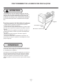
Outdoor Product Long-Term Storage / Winter-
ization: (MO24RF, refrigerator freezer):
1. Time to Winterize, when the daily low ambient tempera-
ture is at or below 38°F (3.3°C).
!
CAUTION
Operation of the unit at ambient temperatures below the
recommended Winterization temperature will void your war-
ranty.
2. Turn unit off, (see page 13)
3. Remove all contents.
4. If necessary, move the unit so you can gain access to
the rear of the product.
5. Unplug the unit from the power outlet.
6. It is also recommended that the power to the outlet be
turned-off if the circuit is not required for other items
during the Winter season.
7. When cleaning unit pay particular attention to any
cracks and crevices that may have accumulated dirt
and debris.
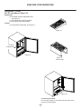
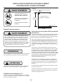
8. Remove the front toe-grille, (see Figure 20), and use a
brush and vacuum to clean dirt and debris from be-
neath the unit.
9. Thoroughly clean the toe-grille and re-install on the
unit. (See Figure 20).
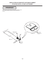
10. Remove the rear access cover, (see Figure 21), and
use a brush and vacuum to clean dirt and debris from
the machine compartment.
11. Thoroughly clean the rear access cover and re-install
on the unit.
12. Wipe down all interior surfaces with anti-bacterial
cleaner to be followed with clean rinse water to remove
any residual chemicals which could cause staining. Do
not use any abrasive cleaners or scouring pads.
13. Leave the door open and allow to completely dry out
before closing the door.
14. Thoroughly clean the door gasket with anti-bacterial
cleaner to be followed with clean rinse water to remove
any residual chemicals.
15. Thoroughly clean the exterior with a cleaner approved
for stainless steel. Do not use any abrasive cleaners or
scouring pads. See "Stainless Steel Maintenance" on
page 22.
16. Any mounting hardware / fasteners that are showing
signs of corrosion should be replaced.
17. Once the exterior has been thoroughly cleaned, you
may want to apply a coating of car wax to help protect
against spotting from moisture, dirt, and debris that
may accumulate on the surfaces during the Winteriza-
tion period.
• If the plastic defrost drain pan located under the
compressor contains water, use a sponge to
remove as much water as possible.

19
CARE AND CLEANING
Start-Up After Long-Term Storage:
1. If stored outside, it is recommended that the unit again
be thoroughly inspected per the storage instructions
above to address any dirt or debris from the weather
and/or animals/insects.
2. Connect the unit to electrical power.
3. Turn unit on and conrm your desired control settings.
4. Allow 24-hrs for the unit to stabilize before loading
contents.
Figure 20
Grille
Spacer
Clean out
behind
grille
Figure 21
Soak up
water from
plastic drain
pan if
necessary
Clean out
debris
Remove screws
around perimeter
of access cover.
18. Do not place a cover on the unit, as this can trap con-
densation.
After completion of the above, you may choose to store the
unit indoors, although this is not required.
Remove screw from
each end of grille
Access cover

20
!
CAUTION
Operation of the unit at ambient temperatures below the
recommended Winterization temperature will void your war-
ranty.
2. Raise the bail arm of the ice maker ( see Figure 8 on
page 7) to stop ice production.
3. Turn the water supply to the unit off.
4. If necessary, move the unit so you can gain access to
the rear of the product.
5. Disconnect the water supply line from the water ll
valve located on the back of the unit, (see page 6).
6. Be sure the exterior water supply line is drained or
blown out to prevent freezing and cracking of the sup-
ply line.
7. We recommend a cap be placed on the water supply
line to prevent dirt and insects from plugging the line.
8. Empty the ice bucket and replace the ice bucket in unit.
9. Lower the ice maker bail arm to allow the unit to oper-
ate until ice is dispensed from ice maker to empty the
ice maker mold.
10. Raise the bail arm and remove the ice bucket and
clean thoroughly with warm water and dish soap.
11. Turn unit off to defrost ice storage compartment, see
page 12).
12. Unplug the unit from the power outlet.
13. It is also recommended that the power to the outlet is
turned-off if the circuit is not required for other items
during the winter season.
14. When cleaning the unit pay particular attention to any
cracks and crevices that may have accumulated dirt
and debris.
15. Remove the front toe-grille, (see Figure 22), and use a
brush and vacuum to clean dirt and debris from be-
neath the unit.
16. Thoroughly clean the toe-grille and re-install on the
unit. (See Figure 22).
17. Remove the solenoid cover and 3 screws. (see Figure
23). Remove the rear access cover, (see Figure 23),
and use a brush and vacuum to clean dirt and debris
from the machine compartment.
18. Disconnect the plastic water line from the bottom of the
solenoid valve (see Figure 23a) and drain. Reconnect
the water line.
Outdoor Product Long-Term Storage / Winter-
ization: (MO24RF, with optional ice maker):
1. Time to Winterize, when the daily low ambient tempera-
ture is at or below 38°F (3.3°C).
CARE AND CLEANING
Figure 22
Grille
Spacer
Clean out
behind
grille
Remove screw from
each end of grille
19. Thoroughly clean the rear access cover and re-install
on the unit.
20. Wipe down all interior surfaces with anti-bacterial
cleaner to be followed with clean rinse water to remove
any residual chemicals which could cause staining. Do
not use any abrasive cleaners or scouring pads.
21. Leave the door open and allow to completely dry out
before closing the door.
22. Thoroughly clean the door gasket with anti-bacterial
cleaner to be followed with clean rinse water to remove
any residual chemicals.
23. Thoroughly clean the exterior with a cleaner approved
for stainless steel. Do not use any abrasive cleaners or
scouring pads. See "Stainless Steel Maintenance" on
page 22.
24. Any mounting hardware / fasteners that are showing
signs of corrosion should be replaced.
25. Once the exterior has been thoroughly cleaned, you
may want to apply a coating of car wax to help protect
against spotting from moisture, dirt, and debris that
may accumulate on the surfaces during the Winteriza-
tion period.
• If the plastic defrost drain pan located under the
compressor contains water, use a sponge to
remove as much water as possible.
La page est en cours de chargement...
La page est en cours de chargement...
La page est en cours de chargement...
La page est en cours de chargement...
La page est en cours de chargement...
La page est en cours de chargement...
La page est en cours de chargement...
La page est en cours de chargement...
La page est en cours de chargement...
La page est en cours de chargement...
La page est en cours de chargement...
La page est en cours de chargement...
La page est en cours de chargement...
La page est en cours de chargement...
La page est en cours de chargement...
La page est en cours de chargement...
La page est en cours de chargement...
La page est en cours de chargement...
La page est en cours de chargement...
La page est en cours de chargement...
La page est en cours de chargement...
La page est en cours de chargement...
La page est en cours de chargement...
La page est en cours de chargement...
La page est en cours de chargement...
La page est en cours de chargement...
La page est en cours de chargement...
La page est en cours de chargement...
La page est en cours de chargement...
La page est en cours de chargement...
La page est en cours de chargement...
La page est en cours de chargement...
La page est en cours de chargement...
La page est en cours de chargement...
La page est en cours de chargement...
La page est en cours de chargement...
La page est en cours de chargement...
La page est en cours de chargement...
La page est en cours de chargement...
La page est en cours de chargement...
La page est en cours de chargement...
La page est en cours de chargement...
La page est en cours de chargement...
La page est en cours de chargement...
La page est en cours de chargement...
La page est en cours de chargement...
La page est en cours de chargement...
La page est en cours de chargement...
La page est en cours de chargement...
La page est en cours de chargement...
La page est en cours de chargement...
La page est en cours de chargement...
La page est en cours de chargement...
La page est en cours de chargement...
La page est en cours de chargement...
La page est en cours de chargement...
La page est en cours de chargement...
La page est en cours de chargement...
La page est en cours de chargement...
La page est en cours de chargement...
La page est en cours de chargement...
La page est en cours de chargement...
La page est en cours de chargement...
La page est en cours de chargement...
-
 1
1
-
 2
2
-
 3
3
-
 4
4
-
 5
5
-
 6
6
-
 7
7
-
 8
8
-
 9
9
-
 10
10
-
 11
11
-
 12
12
-
 13
13
-
 14
14
-
 15
15
-
 16
16
-
 17
17
-
 18
18
-
 19
19
-
 20
20
-
 21
21
-
 22
22
-
 23
23
-
 24
24
-
 25
25
-
 26
26
-
 27
27
-
 28
28
-
 29
29
-
 30
30
-
 31
31
-
 32
32
-
 33
33
-
 34
34
-
 35
35
-
 36
36
-
 37
37
-
 38
38
-
 39
39
-
 40
40
-
 41
41
-
 42
42
-
 43
43
-
 44
44
-
 45
45
-
 46
46
-
 47
47
-
 48
48
-
 49
49
-
 50
50
-
 51
51
-
 52
52
-
 53
53
-
 54
54
-
 55
55
-
 56
56
-
 57
57
-
 58
58
-
 59
59
-
 60
60
-
 61
61
-
 62
62
-
 63
63
-
 64
64
-
 65
65
-
 66
66
-
 67
67
-
 68
68
-
 69
69
-
 70
70
-
 71
71
-
 72
72
-
 73
73
-
 74
74
-
 75
75
-
 76
76
-
 77
77
-
 78
78
-
 79
79
-
 80
80
-
 81
81
-
 82
82
-
 83
83
-
 84
84


dans d''autres langues
- English: AGA marvel MO24RF User guide
- español: AGA marvel MO24RF Guía del usuario
Documents connexes
Autres documents
-
Lynx LM24REFCR / LM24REFCL Le manuel du propriétaire
-
Marvel MA15CRS1RS Mode d'emploi
-
Viking VRUO5240DLSS Guide d'installation
-
-
Marvel MO24FAS1RS Manuel utilisateur
-
-
Marvel MO24RFS2LS Manuel utilisateur
-
-
-