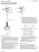
Kichler Lighting 44307LBL Manuel utilisateur
- Taper
- Manuel utilisateur

IS-44307-CB
We’re here to help 866-558-5706
Hrs: M-F 9am to 5pm EST
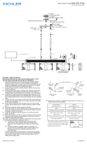
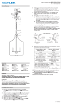
1) Aach chain link[F] to the top loop of the main body[G].
Aach chain to the loop on the canopy[D]. Close the
loops.
2) Weave electrical wire and ground wire through chain
links no more than 3 inches apart. Pass wire through
canopy.
3) Aach mounng strap[A] to outlet box[B] using the
strap mounng screws[C]. Mounng strap can be
adjusted to suit posion of xture.
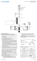
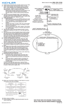
4) Grounding instrucons: (See Illus. a or b).
a) On xtures where mounng strap is provided with a
hole and two raised dimples, wrap ground wire from
outlet box around green ground screw, and thread
into hole.
b) On xtures where a cupped washer is provided,
aach ground wire from outlet box under cupped
washer and green ground screw, and thread into
mounng strap.
If xture is provided with ground wire, connect xture
ground wire to outlet box ground wire with wire
connector (Not provided) aer following the above steps.
Never connect ground wire to black or white power
supply wires.
5) Make wire connecon. Reference chart below for correct
connecons and wire accordingly.
Connect Black or Red
Supply Wire to:
Connect White Supply
Wire to:
Black White
*Parallel cord (round &
smooth)
*Parallel cord (square &
ridged)
Clear, Brown, Gold or
Black without Tracer
Clear, Brown, Gold or Black
with Tracer
Insulated wire (other
than green) with copper
conductor
Insulated wire (other
than green) with silver
conductor
*Note: When parallel wire (SPT
1 & SPT 2) are used. The neutral
wire is square shaped or ridged
and the other wire will be round
in shape or smooth (see illus.)
Neutral Wire
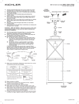
6) Push xture to ceiling. Be sure not to pinch wires
between canopy and ceiling.
7) Use the two (2) mounng screws[E] to secure canopy
through the sides of the canopy. Tighten to secure.
8) Take the 3-Light socket adapter[H] and thread into the
socket under the shade. Do not over ghten.
9) Install the recommended bulbs (Not supplied).
GREEN GROUND
SCREW
CUPPED
WASHER
OUTLET BOX
GROUND
FIXTURE
GROUND
DIMPLES
WIRE CONNECTOR
OUTLET BOX
GROUND
GREEN GROUND
SCREW
FIXTURE
GROUND
a
b
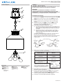
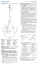
Fixture Diagram
Parts List
Cauons
CAUTION – RISK OF SHOCK –
Disconnect Power at the main circuit breaker panel or main
fusebox before starng and during the installaon.
WARNING:
This xture is intended for installaon in accordance
with the Naonal Electrical Code (NEC) and all local code
specicaons. If you are not familiar with code requirements,
installaon by a cered electrician is recommended.
Installaon Instrucons
[A] Mounting
Strap
[B] Outlet Box
[C] Strap
Mounting
Screws
[D] Canopy
[E] Mounting
Screws
[F] Chain Link
[G] Main Body
[H] Socket
Adaptor
D
C
F
A
E
B
G
H

IS-44307-CB
Nous sommes là pour vous aider 866-558-5706
Heures : du lundi au vendredi, de 9h à 17h (heure de l’Est)
INSTRUCTIONS:
For Assembling and Installing Fixtures in Canada
Pour L’assemblage et L’installaon Au Canada
1) Fixer le maillon de la chaîne[F] sur la boucle du corps
principal[G]. Fixer la chaîne sur la boucle du cache[D].
Fermer les boucles.
2) Tissent le l électrique et l de terre par l’intermédiaire
de chaîne relie pas plus de 3 pouces de distance. Passer
le l à travers la verrière.
3) Fixer l’étrier de montage[A] sur la boîte à prises[B] à
l’aide des vis de xaon de la courroie[C]. L’étrier de
montage peut être réglé en foncon de la posion du
luminaire.
4) Connecter les ls. Se reporter au tableau ci-dessous pour
faire les connexions.
Connecter le l noir ou
rouge de la boite
Connecter le l blanc de
la boîte
A Noir A Blanc
*Au cordon parallèle (rond
et lisse)
*Au cordon parallèle (à
angles droits el strié)
Au transparent, doré,
marron, ou noir sans l
disncf
Au transparent, doré,
marron, ou noir avec un l
disncf
Fil isolé (sauf l vert) avec
conducteur en cuivre
Fil isolé (sauf l vert) avec
conducteur en argent
*Remarque: Avec emploi d’un
l paralléle (SPT 1 et SPT 2). Le
l neutre est á angles droits ou
strié et l’autre l doit étre rond
ou lisse (Voir le schéma).
Fil Neutre
5) Pousser le luminaire vers le plafond. REMARQUE :
S’assurer que les ls ne se coincent pas entre le cache et
le plafond.
6) Uliser les deux (2) vis de montage[E] pour xer le cache
par les côtés du cache. Serrer pour xer.
7) Installer l’adaptateur de douille à 3 lumières[H] dans la
douille située sous le cache. Ne pas serrer avec excès.
8) Installer la ou les ampoules recommandées (Non
fournies).
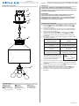
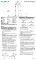
Diagramme d’appareils
ATTENTION – RISQUE DE DÉCHARGES ÉLECTRIQUES -
Couper le courant au niveau du panneau du disjoncteur du
circuit principal ou de la boîte à fusibles principale avant de
procéder à l’installaon.
ATTENTION:
Ce luminaire doit être installé conformément aux codes
d’électricité naonaux (NEC) et sasfaire toutes les
spécicaons des codes locaux. Si vous ne connaissez pas
les exigences de ces codes, il est recommandé de coner
l’installaon à un électricien ceré.
Liste des Pièces
Précauons
[A] L’étrier de
Montage
[B] Boîte à Prises
[C] Vis de Fixation
de la Courroie
[D] Cache
[E] Vis de
Montage
[F] Maillon de la
Chaîne
[G] Corps
Principal
[H] Adaptateur
de Douille
Instrucons d’installaon
D
C
F
A
E
B
G
H
-
 1
1
-
 2
2


Kichler Lighting 44307LBL Manuel utilisateur
- Taper
- Manuel utilisateur
dans d''autres langues
Documents connexes
-
 Kichler Lighting 43896OZ Manuel utilisateur
-
 Kichler Lighting 49747WZC Manuel utilisateur
-
 Kichler Lighting 43869BK Manuel utilisateur
-
 Kichler Lighting 43895OZ Manuel utilisateur
-
 Kichler Lighting 42496NI Manuel utilisateur
-
 Kichler Lighting 44038NI Manuel utilisateur
-
 Kichler Lighting 43871OZ Manuel utilisateur
-
 Kichler Lighting 43534CLP Manuel utilisateur


