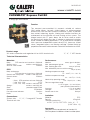
Caleffi NA10923 - 149 FLOWMATIC Coil Kit Mode d'emploi
- Taper
- Mode d'emploi

149 Series
FLOWMATIC® Express Coil Kit
© Copyright 2023 Caleffi
Technical Characteristics
Materials:
Body : DZR corrsion-resistant brass CW602N
Strainer mesh: stainless steel AISI 304
Shut-off valves knobs: PA6G30
PICV
Body and bonnet:
DZR corrsion-resistant brass CW602N
Control stem and piston: stainless steel AISI 303
Control shutter: PPSG40
Seat:
- (G90): DZR corrosion-resistant CW602N
- (1G8, 3G5, 5G3): PTFE
- (7G9, 13G, 16G): stainless steel AISI 303
Springs: stainless steel AISI 302
Seals: peroxide-cured EPDM
Washers: EPDM fiber
Pre-adjustment indicator: PA6G30
Knob: PA6
Connections:
System side: ½”, ¾”, 1” integral NPT female
Terminal unit side:
Performance:
Medium: water, glycol solutions
Max. percentage of glycol: 50%
Max. working pressure: 360 psi (25 bar)
Max. differential pressure with actuators:
58 psi (4 bar)
Working temperature range:
14 – 248°F (-10 – 120 °C)
Ambient temperature range:
32 – 120°F (0 – 50°C)
Nominal ∆p operating range:
3.6 - 58 psi (0.2 - 4 bar)
Flow rate regulation range:
0.1 to 16 gpm (0.4 to 0.6 lpm)
(see hydraulic characteristics)
Accuracy: ± 5% of set point
Leakage: 0.01% (class V)
Strainer mesh size: 800 µm
Insulation:
Material: EPP
Density: 45 kg/m3
Thermal conductivity:
at 50°F (10°C): 0.257 BTU · in/hr · ft² · °F
(0.037 W/m · K))
Approvals:
Compliant with the requirements of standard UL
2043 for plenum installations without insulation jacket.
Function
The compact pre-assembled kit connects variable air volume
(VAV) reheat boxes, fan-coils, chilled beams or ceiling-mounted
terminal units with the main hydronic distribution system. It provides
flow control, balancing, bypass, filtering and isolation functions for
maintenance of the terminal unit and flushing of the system. The
integral venturi with PT ports allows the kit to be sized to match
the terminal unit design flow rate. It includes a preformed insulation
jacket suitable for heating applications. This kit also comes complete
with a pressure independent control valve (PICV), three-way shutoff
valves, integrated bypass and filtering cartridge. Optional on/off or
proportional actuators add automatic control for connection to a BAS.
Product range
149 series connection and regulation kit for HVAC terminal units ½”, ¾”, 1” NPT female
NA10923.01
1
www.caleffi.com

CAUTION: All work must be performed by qualified personnel trained in the
proper application, installation, and maintenance of systems in accordance
with all applicable codes ordinances.
CAUTION: Over-tightening and breakage can occur with the use of Teflon®
pipe joint compounds. Teflon® provides lubricity so that care must be
exercised not to over-tighten joints. Failure to follow these instructions could
result in property damage and / or personal injury.
CAUTION: System fluids under pressure or temperature can be hazardous.
Be sure the pressure has been reduced to zero and the system temperature
is below 100°F (38°C). Failure to follow these instructions could result in
property damage and/or personal injury.
Caleffi shall not be liable for damages resulting from stress corrosion, misapplication or
misuse of its products.
CAUTION: Clean the pipes of any debris, rust, incrustations, welding slag
and any other contaminants. For optimal operation, air in the system must
be removed.
CAUTION: Make sure that all the connecting pipework is water tight. Caleffi
shall not be liable for damages resulting from stress corrosion, misapplication
or misuse of its products.
WARNING: This product can expose you to chemicals including lead, which
is known to the State of California to cause cancer and birth defects or other
reproductive harm. For more information go to www.P65Warning.ca.gov.
This safety alert symbol will be used in this manual to draw attention to safety related
instructions. When used, the safety alert symbol means ATTENTION! BECOME ALERT!
YOUR SAFETY IS INVOLVED! FAILURE TO FOLLOW THESE INSTRUCTIONS
MAY RESULT IN A SAFETY HAZARD.
SAFETY INSTRUCTION
2

Ce symbole d’avertissement servira dans ce manuel à attirer l’attention sur la sécurité
concernant instructions. Lorsqu’il est utilisé, ce symbole signifie. ATTENTION! DEVENEZ
ALERTE ! VOTRE SÉCURITÉ EST EN JEU ! NE PAS SUIVRE CES INSTRUCTIONS PEUT
PROVOQUER UN RISQUE DE SECURITE.
Caleffi ne pourra etre tenue responsable des dommages resultant de la corrosion, d’une
mauvaise utilisation ou une mauvaise utilisation des produits.
AVERTISSEMENT: Ce produit peut vous exposer à des produits chimiques
comme le plomb, qui est connu dans l’État de Californie pour causer le
cancer, dommages à la naissance ou autre. Pour plus d’informations rendez-
vous www.P65Warnings.ca.gov.
AVERTISSEMENT: Tous les travaux doivent être effectués par du personnel
qualifié formé à la bonne application, installation et maintenance des
systèmes conformément aux codes et règlements locaux.
AVERTISSEMENT: Un serrage excessif et une rupture peuvent survenir
avec l’utilisation de Teflon® composés de joint de tuyau. Le Teflon® offre
un pouvoir lubrifiant de sorte que les soins doivent être exercé pour ne pas
trop serrer les joints. Non-respect de ces instructions pourrait entraîner des
dommages matériels et / ou des blessures corporelles.
AVERTISSEMENT: Les liquides du système sont sous pression ou de la
température peivent être dangereux. Être sûr que la pression a été réduite
à zéro et la température du système est inférieure à 100°F (38°C). Le non-
respect de ces instructions peut entrainer des dommages matériels et/ou des
blessures.
AVERTISSEMENT: Nettoyer les tuyaux de tout debris, roille, incrustations,
scories de soudure et d’autres contaminants.Pour un fonctionnement optimal,
de l’air dans le system doit etre retire.
AVERTISSEMENT: S’assurer que tous les raccordements sont étanches.
Caleffi ne pourra etre tenue responsable des dommages resultant de la
corrosion, d’une mauvaise utilisation ou une mauvaise utilisation des produits.
CONSIGNE DE SÉCURITÉ
3

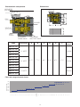
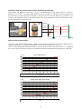
Flow rate range shortcut charts
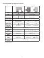
Characteristic components Dimensions
4
ABCDEF
164 37 206,5 110Ø54 201
DN 15
164 37 206,5 110Ø54 201
DN 20
164 37 206,5 110Ø54 201
DN 25
DN 15
DN 20
DN 25
Massa (kg)
2,4
2,5
3,0
A
B
PN25CR
A
B
PN25CR
ABCDEF
164 37 206,5 110Ø54 201
DN 15
164 37 206,5 110Ø54 201
DN 20
164 37 206,5 110Ø54 201
DN 25
DN 15
DN 20
DN 25
Massa (kg)
2,4
2,5
3,0
A
B
PN25CR
A
B
PN25CR
Kit with Venturi device
Kit without Venturi device
G (m
3
/h)
lpm
G40
G90
1G8
3G5
5G3
13G
16G
8G0
H20
H40
H80
1H2
3H0
3H7
1H8
0.4 0.5 0.6 0.7 0.8 1.2 1.4 1.6 1.8 2.2 2.4 2.6 2.8 3.2 3.4 3.6 3.8321.110.90.350.30.250.20.180.160.140.120.10.080.060.040.020
6.8 8.3 9.8 11.4 13.2 20 25.4 28.4 30.3 38 42 45 49 57 61
5334191715.16.05.34.53.83.43.02.72.31.91.51.150.80.40
1.8 2.2 2.6 3.0 3.5 5.3 6.7 7.5 8.0 10 11 12 13 15 16
149.05.04.54.01.61.41.21.00.90.80.70.60.50.40.30.20.10
GPM
Locking nut code
Code Connections A B C D E F Wt
(lb/kg)
149400A G40
½" NPTF
2 1/8” 7 15/16" 6 ½” 1 ½” 8 1/8” 4 5/16”
5.0/2.3
149400A G90
149400A 1G8
149400A 3G5
149500A G90
¾” NPTF 5.2/2.4
149500A 1G8
149500A 3G5
149500A 5G3
149600A 7G9
1" NPTF 6.3/2.9
149600A 13G
149600A 16G
ACTUATOR
(OPTIONAL)
PICV
BYPASS
VENTURI
THREE-WAY
SHUTOFF VALVE
STRAINER/
DRAIN VALVE
TEST
PORTS

Actuators compatible with PICV valve in 149 coil kit
5
* auto stroke detection
Code 145013 145018 656504 656524
Type Proportional Thermo-Electric
Fail position Fail-in-place Fail safe
closed or
open Normally Closed
Electric supply 24 V AC/DC
Power
consumption 2.5 VA; 1.5 W DC 1 W 1.2 W
Control signal 0 (2)–10 VDC
0 (4)–20 mA 0-10 VDC ON/OFF 0-10 VDC
Opening &
closing time
~ 35 seconds (*) ~ 240 seconds ~ 200 seconds
Protection class NEMA 3 (IP 54)
Ambient temp
range 32 - 120°F (0 - 50°C) 32 - 140°F (0 - 60°C)
Feedback signal 0 - 10 V --- 0 - 10 V
Supply cable
length
78 inches (2 m) 39 inches (1 m)
Connection M30 p.1.5 M30 p.1.5 (quick coupling)
Force 36 lbf (160 N) 23 lbf (100 N) 28 lbf (125 N)
Max. differential
pressure 58 psid (4 bar)

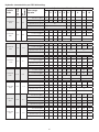
Hydraulic characteristics per PICV dial setting
Coil Kit
code
PICV size
Cv
Venturi
ow range
Δp min
Adjustment position (max ow rate)
1 2 3 4 5 6 7 8 9 10
149400A
G40 1/2” 0.3
0.3 to 1.5 (lpm) 0.3 0.6 0.9 1.2 1.5 -- -- -- -- --
0.1 to 0.4 (gpm) 0.1 .16 .24 .32 0.4 -- -- -- -- --
∆p min PICV (kPa) 25 -- -- -- -- --
∆p min PICV (psi) 3.62 -- -- -- -- --
149400A
G90 1/2” 0.6
1.5 to 3.4 (lpm) -- -- -- -- 1.5 2.0 2.4 2.7 3.0 3.4
0.4 to 0.9 (gpm) -- -- -- -- 0.4 0.5 0.6 0.7 0.8 0.9
∆p min PICV (kPa) -- -- -- -- 25 25.5 26
∆p min PICV (psi) -- -- -- -- 3.62 3.7 3.8
149400A
1G8 1/2” 1.3
3.5 to 6.8 (lpm) -- -- -- -- 3.5 4.1 4.8 5.5 6.1 6.8
0.9 to 1.8 (gpm) -- -- -- -- 0.9 1.1 1.3 1.5 1.6 1.8
∆p min PICV (kPa) -- -- -- -- 26 26.5 27
∆p min PICV (psi) -- -- -- -- 3.8 3.85 3.9
149400A
3G5 1/2” 2.7
6.6 to 13.2 (lpm) -- -- -- -- 6.6 7.9 9.3 10.6 12 13.2
1.9 to 3.5 (gpm) -- -- -- -- 1.9 2.1 2.5 2.8 3.2 3.5
∆p min PICV (kPa) -- -- -- -- 26 27 27.5 28 28.5 29
∆p min PICV (psi) -- -- -- -- 3.6 3.9 4.0 4.06 4.1 4.2
149500A
G90 3/4” 0.6
1.5 to 3.4 (lpm) -- -- -- -- 1.5 2.0 2.4 2.7 3.0 3.4
0.4 to 0.9 (gpm) -- -- -- -- 0.4 0.5 0.6 0.7 0.8 0.9
∆p min PICV (kPa) -- -- -- -- 25 25.5 26
∆p min PICV (psi) -- -- -- -- 3.62 3.7 3.8
149500A
1G8 3/4” 1.3
3.5 to 6.8 (lpm) -- -- -- -- 3.5 4.1 4.8 5.5 6.1 6.8
0.9 to 1.8 (gpm) -- -- -- -- 0.9 1.1 1.3 1.5 1.6 1.8
∆p min PICV (kPa) -- -- -- -- 26 26.5 27
∆p min PICV (psi) -- -- -- -- 3.8 3.85 3.9
149500A
3G5 3/4” 2.7
6.6 to 13.2 (lpm) -- -- -- -- 6.6 7.9 9.3 10.6 12 13.2
1.9 to 3.5 (gpm) -- -- -- -- 1.9 2.1 2.5 2.8 3.2 3.5
∆p min PICV (kPa) -- -- -- -- 26 27 27.5 28 28.5 29
∆p min PICV (psi) -- -- -- -- 3.6 3.9 4.0 4.06 4.1 4.2
149500A
5G3 3/4” 5.8
13.2 to 20 (lpm) -- -- -- -- -- -- 13.2 16 18 20
3.5 to 5.3 (gpm) -- -- -- -- -- -- 3.5 4.2 4.8 5.3
∆p min PICV (kPa) -- -- -- -- -- -- 26.5 27 27.5 28
∆p min PICV (psi) -- -- -- -- -- -- 3.8 3.9 4.0 4.06
6

Venturi hydraulic characteristics
Coil Kit
code
PICV size
Cv
Venturi
ow range
Δp min
Adjustment position (max ow rate)
1 2 3 4 5 6 7 8 9 10
149600A
7G9 1” 5.8
21 to 30 (lpm) -- -- -- -- -- -- 21 24 27 30
5.3 to 7.9 (gpm) -- -- -- -- -- -- 5.3 6.3 7.1 7.9
∆p min PICV (kPa) -- -- -- -- -- -- 25
∆p min PICV (psi) -- -- -- -- -- -- 3.62
149600A
13G 1” 11.1
30 to 49 (lpm) -- -- -- -- -- 30 344 39 44 49
7.9 to 13 (gpm) -- -- -- -- -- 7.8 9.1 10.4 11.7 13
∆p min PICV (kPa) -- -- -- -- -- 35
∆p min PICV (psi) -- -- -- -- -- 5
149600A
16G 1” 11.1
30 to 60 (lpm) -- -- -- -- 3036 4248 55 60
8 to 16 (gpm) -- -- -- -- 8 9.6 11.2 12.8 14.4 16
∆p min PICV (kPa) -- -- -- -- 45 43
∆p min PICV (psi) -- -- -- -- 6.5 6.2
7
0. 1
10
0.023
0. 23
0.046
0.069
0.02
0.05
0. 2
0. 5
0.115
2.3
0.46
0.69
1.15
20
50
∆
p (ft of head)
G (lpm) (
gpm
)
23
4.6
6.9
11.5
46
0.01
0. 1
0.02
0.03
0.05
1
0. 2
0. 3
0. 5
(psi) (kPa)
10
2
3
5
20
1
0.1
0.2
0.5
0.0 5
10
2
5
20
0.1
1
0.2
0.3
0.5
10
2
3
5
1
00
20
30
50
9.2
0.092
0.92
0.04
0. 4
4
0.4
4
40
50
115
161
50
70
20
0
50
0
190
70
100
140
Cv
size 5G3-7G9
5.80
3G5
2.70
1G8
1.30
G90
0.60
G40
0.30
13G-16G
11.1
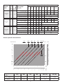
Locking nut
code G40 G90 1G8 3G5 5G3-7G9 13G-16G
Flow range (gpm) 0.1-0.4 0.4-0.9 0.9-1.8 1.8-3.5 3.5-7.9 7.9-16
Cv Venturi 0.3 0.6 1.3 2.7 5.8 11.1

Three-way ball valve
The shut-off valves have three positions. The internal ball is designed to open the straight path
(A) (for normal operation), the bypass path (B) (for passage through the bypass) or to completely
close the passage and isolate the circuit of the terminal unit (C).
Integrated by-pass
The kit is equipped with a bypass, which is used for:
• flushing the main circuit pipes without the fluid
passing through the terminal unit;
• isolation for maintenance work on the terminal unit.
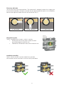
Installation versatility
The kit, without actuator, can be installed in any position.
With actuator, do not install the kit with the valve upside down.
8
A - UNIT OPEN B - UNIT BY-PASS C - UNIT CLOSE
Versatilità di installazione
Il gruppo, senza attuatore, può essere montato in qualsiasi posizione.
Con attuatore montato, solo l’installazione capovolta non è consentita.
Particolarità costruttive
Corpo compatto
Il gruppo è progettato appositamente di ridotte dimensioni, compatto e di semplice installazione per agevolare il collegamento dell’unità terminale al
circuito principale.
20 connessioni
idrauliche
Componenti singoli assemblati in cantiere Gruppo pre-assemblato
4 connessioni
idrauliche
Installazione
laboriosa e ad alto
rischio di perdita
idraulica
Facilità di
installazione e
basso rischio di
perdita idraulica
Valvola a sfera a tre vie
Le valvole di intercettazione sono state
progettate a tre vie per ridurre il più
possibile le dimensioni e le connessioni
del kit. La sfera interna è progettata
per aprire la via diritta (A) (per il normale
funzionamento), la via by-pass (B)
(per il passaggio attraverso il by-pass)
oppure per chiudere completamente il
passaggio ed isolare il circuito dell’unità
terminale (C).
By-pass integrato
Il gruppo è completo di by-pass,
elemento indispensabile per ciascun
circuito terminale. Il by-pass consente
infatti di:
• eseguire le operazioni di ussaggio,
lavaggio e pulizia dei tubi del
circuito principale senza passaggio
di uido attraverso l’unità terminale;
• eseguire le operazioni di
intercettazione e manutenzione
dell’unità terminale.
A - UNIT OPEN
B - UNIT BYPASS C - UNIT CLOSE
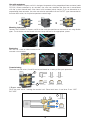
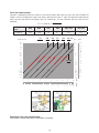
Principio di funzionamento
Il gruppo può essere schematizzato come segue:
1. Attuatore (opzionale)
2. Valvola di regolazione indipendente dalla pressione (PICV)
3. Rubinetto di carico/scarico (opzionale)
4. Dispositivo Venturi per la misura della portata completo di
attacchi per prese di pressione (presente solo nei codici
149.00)
5. Valvola di intercettazione a 3 vie
6. By pass
7. Valvola di intercettazione con ltro integrato
Il gruppo permette di:
• regolare e mantenere costante la portata dell’unità terminale
al variare delle condizioni di pressione differenziale del circuito
principale grazie alla valvola di regolazione indipendente dalla
pressione PICV (2);
• isolare l’unità terminale attraverso le valvole di intercettazione a
3 vie (5-7);
• bypassare il usso attraverso le valvole di intercettazione a tre vie
(5-7) e il by pass integrato (6);
• ltrare l’acqua in ingresso all’unità terminale attraverso il ltro
posizionato all’interno della valvola di intercettazione (7);
• misurare la portata passante nell’unità terminale grazie al
dispositivo con effetto Venturi ed alle prese di pressione (4)
con le quali è agevole il collegamento dello strumento di misura
(presente solo nei codici 149.00);
• eseguire la pulizia del circuito e scaricare l’acqua tramite il
rubinettino di scarico (opzionale) (3)
3
1
2
5
7
6
4
IMPIANTO
UNITA’
TERMINALE

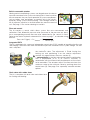
Built-in removable strainer
Heating and air conditioning systems can degrade over time due to
impurities contained in the system circulating fluid. If these impurities
are not removed, they can impair operation of system components,
such as boilers, heat exchangers, or terminal units in the circuits,
especially during system commissioning. The cartridge strainer in
the kit captures impurities in the fluid before they reach the terminal
unit. See page 11 for strainer cleaning instructions.
Flow rate venturi
The kit contains a venturi which allows system flow rate measurement and
verification. Each differential pressure value (measured at the pressure test ports)
has a corresponding accurate flow rate value, determined by the venturi Cv value.
Refer to the Venturi hydraulic characteristics chart on page 7, or calculate using
formula:
Flow rate G (gpm) = Cv Venturi x √∆p Venturi (psi)
• manually on the automatic flow rate regulator, to restrict
the maximum value. The adjustment is made turning the
locking nut and positioning it on the relative adjustment
number: this opens/closes the cross section (A)
• automatically by the flow rate control valve in combination
with a proportional (0–10 V) or ON/OFF actuator, in
accordance with the thermal load requirements of the circuit
to be controlled. The actuator adjusts the flow rate from the
maximum value to the minimum value by pushing down the
control stem (B). See page 5 for separately sourced actuator
options.
Drain valve with rubber hose
The kit is complete with drain valve and rubber hose
for flushing and draining.
9
Integrated PICV
The kit is equipped with a pressure independent control valve (PICV) capable of regulating the flow rate
and keeping it constant even when the differential pressure conditions of the system change. The flow
rate is adjusted:
B
A

Mounting instructions
Connect the FLOWMATIC Express coil kit to the main pipe and then to the terminal unit using flexible
pipes. The insulation can be closed with the clamps housed in the appropriate spaces.
Bracketing
The unit has a hole to allow bracket to be
mounted as shown below.
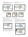
Commissioning
The three-way ball valves (A and B) can be positioned for a variety of flow path operations.
1) Bypass mode:
Flush the main circuit, isolating the terminal unit. Place both lever A and lever B on “UNIT
BY-PASS”.
10
UNIT BY-PASS
UNIT BY-PASS
UNIT OPEN
UNIT OPEN
UNIT CLOSE
UNIT CLOSE
UNIT BY-PASS
UNIT BY-PASS
Use with actuators
(1) The
FLOWMATIC Express coil
kit is designed to operate with a proportional linear actuator (code
145013). When controlled by an actuator, the valve can modulate the flow rate in accordance
with the system thermal load. Also shown with insulaton jacket closed. (2) As an alternative to a
proportional linear actuator, the valve can also be controlled with an ON/OFF type thermo-electric
actuator 656 series, for simple temperature control logic.
1 2
B
A
A
B

2) Terminal unit flushing:
Position lever A at “UNIT OPEN” and lever B
at “UNIT CLOSE”, screw on the rubber hose
and unscrew the drain valve.
(a) Loosen the locking nut (by about 2 turns) to drain the water from the terminal unit circuit. (b) Unscrew
the strainer cartridge with a 20 mm wrench. (c) Remove the strainer holder cartridge and clean the
strainer under running water.
4) Purging the terminal unit:
Position lever A at “UNIT OPEN” and lever
B at “UNIT CLOSE”, and open the PICV
with the corresponding knob. Close the
drain valve as soon as the air is completely
eliminated.
6) Isolate the lines, service the terminal unit:
The terminal unit can be cutoff and thus isolate
the secondary circuit. This procedure is used to
perform maintenance on the terminal unit.
5) Normal operation:
Normal operation involves positioning both
valves on “OPEN”. Water passes through the
strainer before entering in the terminal unit,
protecting the unit against impurities in the main
circuit water.
3) Strainer cleaning
To clean the strainer position both levers on
“UNIT CLOSE”.
11
A
B
UNIT OPEN
UNIT OPEN
UNIT CLOSE
UNIT OPEN
UNIT CLOSE
UNIT CLOSE
UNIT OPEN
ab c
UNIT CLOSE
UNIT CLOSE
Caution:
Tighten the locking nut fully and check that there are no leaks.
A
B
UNIT CLOSE
A
B
A
B
A
B

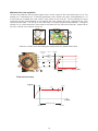
Maximum ow rate regulation
Unscrew the protective cap by hand to gain access to the maximum flow rate adjustment nut (a). The
locking nut is connected to a 10-position graduated scale, divided into steps corresponding to 1/10
of the maximum available flow rate, which is also shown on the scale (b). Turn the locking nut to the
numerical position corresponding to the required flow rate (design flow rate), referring to the “Flow
rate adjustment table”. The slot (c) on the valve body is the physical positioning reference. Turning the
locking nut (a), which determines the number associated with the “Adjustment position”, opens/closes
the cross section in the control shutter (d).
Each cross section set on the locking nut corresponds to a specific Gmax value.
12
a
d
∆p*
minimum
p (psi)
3.6 psi 4.4 psi 60 psi
Gmax10
Gmax8
Gmax6
Gmax
x
Adjustment
position
10
8
6
Gmax1
1
G (gpm)
a
b
c
Dp *
minimum
G6
G8
G10
Dp (kPa)
G1
25 kPa 30 kPa 400 kPa
G (m3/h)
Working range
G (gpm)
±5 %
p min p max
p (kPa)
± 10 %
± 10 %
G (m3/h)
±5 %
Dp min Dp max
Dp (kPa)
± 10 %
± 10 %
set point
Working range
Working range
Flow rate accuracy

Automatic ow rate control with actuator and external controller
After setting the maximum flow rate,
a 0 to 10 V proportional actuator (code 145013, 145018 or
656524) or an ON/OFF actuator (code 656504) can be installed, to control the PICV between the
maximum flow rate and closed. For example, if the maximum flow rate has been set to position 8, the
actuator can modulate the flow rate automatically from 8 to completely closed. The actuator pushes
on the spring-return control stem (a).
Valve control characteristics
The PICV valve control characteristic is linear. An increase or decrease in the valve opening cross
section corresponds to a directly proportional increase or decrease of the valve Cv.
The 145 series proportional actuator motor is factory set for a linear flow characteristic. Or, changing
the switch setting inside the actuator can provide an equal-percentage flow characteristic, if desired.
13
a
% Cv
max
Linear adjustment
Equal percentage adjustment
% stroke
% Cv
max
% stroke
% Cv
max
Linear adjustment
Equal percentage adjustment
% stroke
% Cv
max
% stroke
∆p minimum
Δ
p (psi)
G (gpm)
Gmax8
50% Gmax8
75% Gmax8

Flow rate measurement
Connect a differential pressure meter to the Venturi device pressure test ports on the FLOWMATIC
Express coil kit. Reading the ∆p on the meter, read the flow rate, G, from the hydraulic characteristic
flow curve for the Venturi size being used. Or, analytically, you can calculate the flow rate with this
equation:
Example of ow rate measurement
See Caleffi Technical Brochure 01336-NA for example.
14
G = Cv Venturi x √∆p Venturi
Locking nut
code G40 G90 1G8 3G5 5G3-7G9 13G-16G
Cv Venturi 0.3 0.6 1.3 2.7 5.8 11.1
0. 1
10
0.023
0. 23
0.046
0.069
0.02
0.05
0. 2
0. 5
0.115
2.3
0.46
0.69
1.15
20
50
∆p (ft of head)
G (lpm) (
gpm
)
23
4.6
6.9
11.5
46
0.01
0. 1
0.02
0.03
0.05
1
0. 2
0. 3
0. 5
(psi) (kPa)
10
2
3
5
20
1
0
.1
0.2
0.5
0.0 5
10
2
5
20
0.1
1
0.2
0.3
0.5
10
2
3
5
1
00
20
30
50
9.2
0.092
0.92
0.04
0. 4
4
0.4
4
40
50
115
161
50
70
200
500
190
70
100
140
Cv
size 5G3-7G9
5.80
3G5
2.70
1G8
1.30
G90
0.60
G40
0.30
13G-16G
11.1
Δp(psi) Δp
(measure)

15
NOTES

16
Caleffi North America, Inc.
3883 West Milwaukee Road
Milwaukee, WI 53208
T: 414.238.2360 F: 414.238.2366
09-2023
For Technical Support call 1-414-338-6338, or
email techsupport.us@calef.com
Optional Insulation Jacket
This insulation jacket fully covers the assembly, if desired, and can be easily field installed, replacing
the standard supplied smaller jacket.
Code: F0001771
Material: EPP
Density: 30 kg/m3
Thermal conductivity:
at 50°F (10°C): 0.257 BTU · in/hr · ft² · °F
(0.037 W/m · K))
-
 1
1
-
 2
2
-
 3
3
-
 4
4
-
 5
5
-
 6
6
-
 7
7
-
 8
8
-
 9
9
-
 10
10
-
 11
11
-
 12
12
-
 13
13
-
 14
14
-
 15
15
-
 16
16


Caleffi NA10923 - 149 FLOWMATIC Coil Kit Mode d'emploi
- Taper
- Mode d'emploi
dans d''autres langues
Documents connexes
Autres documents
-
Johnson Controls VP140LCA Installation Instructions Manual
-
Johnson Controls VP10JDB Series Manuel utilisateur
-
sauter NRFC 413, 422…424 Assembly Instructions
-
-
Laars JVS160P Guide d'installation
-
FläktGroup COM4plus Guide d'installation
-
Rinnai E110SRN Mode d'emploi