Jøtul Cube 200 AL Instruction And Operation Manual
- Catégorie
- Cheminées
- Taper
- Instruction And Operation Manual
Ce manuel convient également à

Monterings- og bruksanvisningen må oppbevares under hele produktets levetid. These instructions must
be kept for future references. Ce manuel doit être conservé pour de futures interventions. Wir empfehlen
Ihnen, die Montage- und Bedienungsanleitung für spätere Zwecke sorgfältig aufzubewahren.
Jøtul Cube 200 / 400 / 500 / 530
Manual Version P02
Jøtul Cube 200 / 400 / 500 / 530
GB - Installation and Operating Instructions 3
FR - Manuel d’installation et d’utilisation 15
ES - Manual de instrucciones 27
IT - Installazione e Istruzioni per l’uso 39
NL - Installatie- en montagehandleiding 51
Jøtul Cube 200 GG
Jøtul Cube 400 GG
Jøtul Cube 500 GG
Jøtul Cube 530 GG
Jøtul Cube 200 GL
Jøtul Cube 400 GL
Jøtul Cube 500 GL
Jøtul Cube 530 GL
Jøtul Cube 200 AG
Jøtul Cube 400 AG
Jøtul Cube 500 AG
Jøtul Cube 530 AG
Jøtul Cube 200 AL
Jøtul Cube 400 AL
Jøtul Cube 500 AL
Jøtul Cube 530 AL


3
ENGLISH
1.0 Relationship with the
authorities
Jøtul Cube is a freestanding product with Jøtul I 400 FL, Jøtul I 500
FL or Jøtul I 530 FL as the burn chamber, which can be positioned
against walls at the distances described in Fig. 1a and Fig. 1b.
Installation of the fireplace must be according to local codes and
regulations in each country. All local regulations, including those
that refer to national and European standards, shall be complied
with when installing the product.
Installation instructions for the surround are included.
Installation and user instructions for the insert are enclosed
with the product.
For day-to-day use, maintenance, servicing, etc., please see this
document. The installation may only be used once it has been
inspected and a certificate of completion has been issued.
Prior to using the product the installation must be approved by
a qualified person.
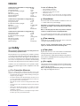
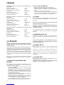
4 name plates of heat-resistant material are enclosed with the
product. The name plate for the chosen combination shall be
placed between the cage and the decor panel (see figure). This
contains information about identification and documentation
for the product.
m.a.b
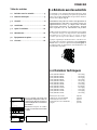
2.0 Technical Data
Weight, Jøtul Cube 400 GG : Approx. 228 kg
Weight, Jøtul Cube 400 GL : Approx. 256 kg
Weight, Jøtul Cube 400 AG : Approx. 219 kg
Weight, Jøtul Cube 400 AL : Approx. 247 kg
Weight, Jøtul Cube 500 GG : Approx. 250 kg
Weight, Jøtul Cube 500 GL : Approx. 278 kg
Weight, Jøtul Cube 500 AG : Approx. 241 kg
Weight, Jøtul Cube 500 AL : Approx. 269 kg
Weight, Jøtul Cube 530 GG : Approx. 243 kg
Weight, Jøtul Cube 530 GL : Approx. 271 kg
Weight, Jøtul Cube 530 AG : Approx. 234 kg
Weight, Jøtul Cube 530 AL : Approx. 262 kg
Height, w/glass decor : 1178 mm
Height, w/aluminium decor : 1182 mm
Depth, w/glass decor : 485 mm
Depth, m/aluminium decor : 481 mm
Width : 780 mm
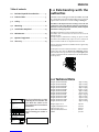
Table of contents
1.0 Relationship with the authorities ...............3
2.0 Technical data ...............................................3
3.0 Safety ........................................................... 6
4.0 Mounting ......................................................8
5.0 Installation completed ............................... 14
6.0 Maintenance .............................................. 14
7.0 Optional equipment .................................. 14
8.0 Warranty ..................................................... 14
On all our products there is a label
indicating the serial number and
year. Write this number in the
place indicated in the installation
instructions.
Always quote this serial number
when contacting your retailer or
Jøtul.
les combustibles recommandés.
Respectez les consignes d'utilisation. Utilisez uniquement
Verwenden Sie nur empfohlenen Brennstoffen.
Montage- und Bedienungsanleitung beachten.
Follow user`s instructions. Use only recommended fuels.
standard
Certificate/
The appliance can be used in a shared flue.
Minimum distance to adjacent combustible materials:
Emission of CO in combustion products
Serial no: Y-xxxx, Year: 200x
Manufacturer:
N-1602 Fredrikstad
Norway
Jøtul AS
POB 1441
Sweden
EUR Intermittent
Nominal heat output
Norway
Country
Operational type
Fuel type
Operation range
Efficiency
Klasse II
Classification
Standard
Flue gas temperature
Room heater fired by solid fuel
Product:
Jøtul
SP Sveriges Provnings- och
221546
Forskningsinstitut AB
SP Swedish National
Testing and Research
Institute
:
Approved by
:
:
:
:
:
:
:
Minimum distance to adjacent combustible materials:
OGC SP
EN
Serial no.

4
ENGLISH
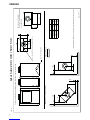
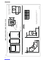
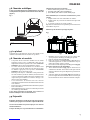
Fig. 1a Jøtul Cube 200 / 400 / 500 / 530
Product: Jøtul Cube 200 / Jøtul Cube 400 / Jøtul Cube 500 / Jøtul Cube 530
Min. measure floorplate
X / Y = Acc. to national regulatives
and regulations.
Hole in floor for external air - Ø100
Access for external air
* Semi insulated chimney / covered flue pipe down towards the product.
Min. distance to combustible wall.
900112-P00
1253
1178
780
485
400
X
Y
Insert A B
Jøtul I 200 FL 247 450
Jøtul I 400 FL 223 433
Jøtul I 500 FL 247 450
Jøtul I 530 FL 245 449
150
150
*50
*50
400
250
*50
A
B
B
Combustible wall

5
ENGLISH
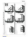
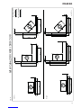
Fig. 1b Jøtul Cube 200 / 400 / 500 / 530
900112-P00
Combustible wall
Firewall
Min. distance to combustible wall protected by approved firewall.
External firewall
Min. distance to combustible wall protected by approved firewall.
Integrated firewall
920
30
30
30 30
30
30 30
30
1120
300
300
1150
1150
1150
1150
1050 1050
1050
1250

6
Technical data for Jøtul I 400 FL according to EN 13229
Nominal heat output: 6,0 kW
Flue gas mass flow: 7,3 g/s
Recommended chimney draught: 12 Pa
Efficiency: 74 %@6,0 kW
CO emission (13% O2): 0,19%
Flue gas temperature: 259 oC
Operational type: Intermittent
Technical data for Jøtul I 500 FL according to EN 13229
Nominal heat output:
9,0 kW
Flue gas mass flow:
8,1 g/s
Recommended chimney draught: 12 Pa
Efficiency: 80%@ 9,9 kW
CO emission (13% O2 ): 0,06 %
Flue gas temperature:
314
o
C
Operational type: Intermittent
Technical data for Jøtul I 530 FL according to EN 13229
Nominal heat output:
9,0 kW
Flue gas mass flow:
8,4 g/s
Recommended chimney draught: 12 Pa
Efficiency: 71%@ 9,0 kW
CO emission (13% O2 ): 0,25 %
Flue gas temperature:
350
o
C
Operational type: Intermittent
3.0 Safety
NB! To guarantee optimal performance and safety, Jøtul stoves
must be fitted by a qualified installer.
Any modifications to the product by the distributor, installer
or consumer may result in the product and safety features not
functioning as intended. The same applies to the installation of
accessories or optional extras not supplied by Jøtul. This may
also be the case if parts that are essential to the functioning
and safety of the fireplace have been disassembled or removed.
In all these cases, the manufacturer is not responsible or liable
for the product and the right to make a complaint becomes null
and void.
3.1 Fire Prevention Measures
There is a certain element of danger every time you use your
fireplace. The following instructions must therefore be followed:
• The minimum safety distances when installing and using the
fireplace are given in fig. 1.
• Ensure that furniture and other flammable materials are not
too close to the fireplace. Flammable materials should not be
placed within 1 metre of the fireplace.
• Allow the fire to burn out. Never extinguish the flames with
water.
• The fireplace becomes hot when lit and may cause burns if
touched.
• Only remove ash when the fireplace is cold. Ash can contain
hot embers and should therefore be placed in a non-
flammable container.
• Ash should be placed outdoors or be emptied in a place where
it will not present a potential fire hazard.
In case of chimney fire:
• Close all hatches and vents.
• Keep the firebox door closed.
• Check the loft and cellar for smoke.
• Call the fire service.
• Before use after a fire an expert must check the fireplace
and the chimney in order to ensure that it is fully functional.
3.2 Foundations
You need to make sure the foundation is suitable for a stove. See
“2.0 Technical data” for specified weight.
Remember: If a steel chimney resting on the burn chamber is
being used, the weight of the steel chimney should be taken
into account.
NB: It is extremely important that the product be stable; the
surface it is installed on must be completely inflexible.
It is recommended that flooring that is not attached to the
foundation – «floating floors» – be removed beneath the product.
3.3 Floor covering
Jøtul Cube has an airtight bottom plate and no extra floor
covering is required beneath the product.
Any floor covering of inflammable material, such as linoleum,
carpets, etc. must be removed from under the product.
3.4 Floor plate
A plate made of steel or some other suitable non-inflammable
metal (optional extra) is placed in front of the hearth.
The floor plate must comply with national laws and regulations.
Contact your local building authorities regarding restrictions and
installation requirements..
3.5 Air supply
There must be a flow of air between the burn chamber and the
surround. This is to ensure that there is not too great a build-up
of heat inside the surround.
NB: It is extremely important that air openings not are covered
up. See Fig. 1a and Fig. 1b for distances.
ENGLISH

7
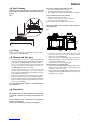
3.6 Steel chimney
When using semi-insulated chimney: It is extremely important
that the shield is all the way down towards the top ring. (see
figure 2)
Fig. 2
m.a.b
3.7 Ceiling
Make sure the room where the Jøtul Cube is to be placed has a
ceiling height of at least 2300 mm.
3.8 Chimney and flue pipe
• The stove must be connected to a chimney and flue pipe
approved for solid fuel fireplaces with flue gas temperatures
as specified in «2.0 Technical data» in the insert manual.
• The cross-section of the chimney must be at least that of the
flue pipe. To calculate the correct chimney cross section, see
«2.0 Technical data» in the insert manual.
• Several solid fuel products can be connected to the same
chimney system if the chimney cross-section is adequate.
Contact your local building authorities regarding restrictions
and installation requirements.
• Connection to the chimney must be performed in accordance
with the installation instructions of the chimney supplier.
• Make sure that the flue pipe rises all the way up to the chimney.
• Please note that it is extremely important for connections to
have a degree of flexibility.
For recommended chimney draught, see «2.0 Technical data» in
the insert manual.
3.9 Preparation
NB: Check that there is no visible damage to the product when
you unpack it, and make sure that the control handles move
freely.
The burn chamber is heavy, – make sure it does not topple over
while you are installing it!
Ensure you have help when positioning and installing it.
ENGLISH
The product is supplied together with 3 manuals:
1. General user and maintenance manual
2. Jøtul Cube 200 / 400 / 500 / 530 (surround).
3. Jøtul I 400 FL, Jøtul I 500 FL or Jøtul I 530 FL (burn chamber).
Prior to installation, decide on the following:
1. Where the smoke outlet should be.
2. Position of external air connection if being used.
3. Ash collection system if being used.
Refer to manuals for parts installation instructions.
Reducing the weight of burn chamber and protecting parts
during installation:
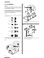
Fig. 3
B
E
A
C
D
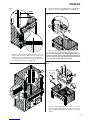
1. Unpack the insert. Take out the box with contents and,
if necessary, burn plates to make the product lighter.
2. Remove the heat shield (Fig. 3 E).
3. Remove the side burn plates (Fig. 3 A) by lifting them
slightly and pulling out. If they are difficult to remove, use
a screwdriver to draw them up.
4. Then lift the back burn plate out (Fig. 3 B).
Special instructions for the Jøtul I 500 FL:
5. Pull the air chamber (Fig. 3 C) forward while lifting it at the
front edge. Ease it down and take it out through the door
opening. Be careful – it is heavy!
6. Lift the exhaust deflector (Fig. 3 D) up at the back edge, push
it slightly backwards. Then lift it down at the front edge, out
through the door opening.

8
4.0 Mounting
Important!
Bear in mind that the parts may be damaged if they are handled
roughly. Installation should be carried out by a qualified person.
Be especially careful in the treatment of the glass panels. Injuries
in the tempered glass will impair its characteristics, and the panel
may explode at the high temperatures it is exposed to.
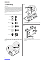
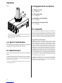
Fig. 4
Overview of nuts and bolts used during mounting of the product:
M6
M5 x 6
DIN 7982
M5 x 16
M6 x 16
M8 x 10
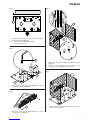
4.1 Mounting of the cage and the insert
Fig. 5a
m.a.b
Fig. 5b
1
2
m.a.b
1. The 3 legs (Fig. 5b.1) are mounted to the bottom plate with
screws (Fig. 5b.2).
Fig. 6
1
2
m.a.b
1. Mount the adjustable feets (Fig. 6.1).
2. If external air through floor: Remove one of the knockouts
(Fig. 6.2).
ENGLISH

9
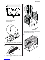
Fig. 7
1
m.a.b
1. Place the bottom plate in the correct distanse from the
wall. Min. distanse (Fig. 7.1):
Against combustible wall: 61 mm.
Against firewall: 41 mm.
Fig. 8
m.a.b
1
2
!
1. Ensure that the bottom plate (Fig. 8.1) is level by adjusting
the screws (Fig. 8.2).
Fig. 9
1
m.a.b
1. Assemble the air intake cover (Optional: cat.no. 50043352)
with 4 screws (Fig. 9.1).
Fig. 10
1
2
m.a.b
1. Assemble the first level sides and back (Fig. 10.1)
2. Mount the air intake cover (Optional: cat.no. 50043352) on
the back (Fig. 10.2) if this is selected.
Fig. 11
m.a.b
1. Lift the first level on to the bottom plate. Grab the sides
when lifting.
ENGLISH

10
Fig. 12
1
2
H
m.a.b
1. Prepare the insert and adjust its height to 815 mm (Fig. 12.H).
Refer the insert manual for instructions.
2. Lift the insert (Fig. 12.1) on to the 3 legs (Fig. 12.2).
Fig. 13
2
1
m.a.b
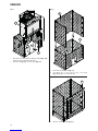
1. Mount the first level front (Fig. 13.1).
2. Assemble the second level sides and back
(Fig. 13.2) and place it on the first level.
Fig. 14
1
m.a.b
1. Mount second level front (Fig. 14.1).
ENGLISH

11
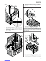
1. Mount the side profiles (Fig. 16.1) with 3 screws (Fig. 16.2).
2. Mount and adjust the front profile (Fig. 16.3) with 2 screws
(Fig. 16.4).
Fig. 17
1
2
m.a.b
1. Mount the bracket (Fig. 17.1) on the back panel.
2. Mount the heat shield (Fig. 17.2) to the bracket.
N.B. It is extremely important that the heat shield is mounted
correctly. If it is mounted wrong the back wall will be exposed to
higher temperature. Then the product has to be placed further
away from the wall.
Fig. 18
Jøtul I 200 FL
Jøtul I 500 FL
Jøtul I 530 FL
Jøtul I 400 FL
1
3
4
2
m.a.b
1. Mount the bracket (Fig. 18.2) between the sides and the
screws of the smoke bell (Fig. 18.4), and from the front to the
smoke bell. (The illustration shows this done on Jøtul I 400 FL)
ENGLISH
Fig. 15
1
2
13 mm
10 mm
m.a.b
1. Adjust the height of the insert. It shall be a gap of 10 mm
between the edge of the door and the upper edge of the
opening in the cage (Fig. 15.1).
2. Adjust the insert position so that the door is 13 mm outside
the cage (Fig. 15.2).
Fig. 16
1
2
3
4
m.a.b

12
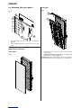
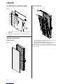
4.2 Mounting the decor panels
Fig. 19
1
2
m.a.b
1. All decor elements have the same system for mounting
(Fig. 19.1).
2. The hooks (Fig. 19.2) shall be attached to holes in the cage
panels.
Mounting the side decor
Glass decor
Fig. 20
m.a.b
Lava decor
Fig. 21
2
1
m.a.b
1. Lava decor for sides consists of 10 elements. Start mounting
at the bottom.
2. If aluminium decor (Fig. 23 - 24): Mount air grid (Fig. 21.1)
before the last 2 elements (Fig. 21.2).
Mounting advice: Lay out all the lava elements on a soft surface.
Distribute them until you get a pattern you are satisfied with.
ENGLISH

13
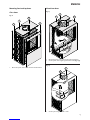
Mounting front and top decor
Glass decor
Fig. 22
12
3
4
m.a.b
1. Mount the panels in the order shown in the illustration.
Aluminium decor
Fig. 23
1
3
2
4
m.a.b
1. Mount the panels in the order shown in the illustration.
2. Join the panels and air grid together with screws (Fig. 23.4).
Fig. 24
2
1
m.a.b
1. Join the panels together with screws.
ENGLISH

14
Fig. 25
1
2
m.a.b
1. Place the decor ring (Fig. 25.1). Select the ring that fits your
chimney.
2. Mount the fluepipe (Fig. 25.2) according to the insert
manual .
5.0 Installation completed
See the General user and maintenance manual for the insert for
the use and maintenance of the product.
6.0 Maintenance
All service must be done when the stove is cold!
Glass surfaces can be cleaned with ordinary product for window
washing. Ensure that no water remains on the surfaces, as this
can cause the glass to explode when heated.
Aluminium surfaces can be cleaned with water and neutral
detergent.
7.0 Optional equipment
7.1 Floor plate
Cat.no. XXXXXXXX
7.2 Wood bag
Cat.no. 50043350
7.3 Fireplace set
Cat.no. 50043349
7.4 Air intake cover
Cat.no. 50043352
8.0 Warranty
JJøtul AS provides its customers with a ten-year warranty with the
right to return external cast-iron items if they show defects as a
result of faulty materials and/or manufacturing after the initial
purchase/installation of the fireplace. The buyer is entitled to
return the goods provided that the fireplace has been installed in
compliance with current laws and regulations and in compliance
with Jøtul’s installation and operating instructions.
The warranty does not cover:
The installation of optional extras, for example, to rectify local
draught conditions, air supply or other circumstances beyond
Jøtul’s control. The warranty does not cover consumables, such
as burn plates, smoke baffles, fire grates, bottom grates, brick
refractories, dampers and gaskets as they deteriorate over time
due to normal wear and tear. The warranty does not cover damage
caused as a result of using unsuitable fuel when lighting the fire,
such as driftwood, impregnated and painted wood, plank offcuts,
chipboard, etc. Overheating may easily occur if unsuitable fuel is
used, i.e. the fireplace becomes red hot, which causes the paint
to discolour and the cast iron parts to crack.
The warranty is not valid for damage caused while the product
is in transit from the distributor to the delivery address. The
warranty is not valid either for damage caused by the use of
non-original parts.
ENGLISH

15
FRANCAIS
1.0 Relations avec les autorités
Le Jøtul Cube est un appareil indépendant utilisant le Jøtul I
400 FL, Jøtul I 500 FL ou Jøtul I 530 FL pour foyer, pouvant être
placé contre des murs inflammables en respectant les distances
décrites dans la fig. 1a et fig. 1b.
L’installation d’un poêle est soumise aux législations et
réglementations nationales en vigueur. Toutes les
réglementations locales, y compris celles relatives
aux normes nationales et européennes, doivent
être respectées lors de l’installation du produit.
Veuillez contacter les autorités locales compétentes pour connaître
les restrictions d’usage et les exigences liées à l’installation.
L’installation ne pourra être mise en service qu’après
contrôle par un inspecteur habilité, suivant les pays.
4 plaques signalétiques thermorésistantes sont livrées avec
le produit. Placez la plaque signalétique pour la combinaison
choisie entre le caisson et le panneau décor (voir la figure). Ce
document fournit des informations sur l’identification et la
documentation du produit.
m.a.b
2.0 Données techniques
Poids, Jøtul Cube 400 GG : Env. 228 kg
Poids, Jøtul Cube 400 GL : Env. 256 kg
Poids, Jøtul Cube 400 AG : Env. 219 kg
Poids, Jøtul Cube 400 AL : Env. 247 kg
Poids, Jøtul Cube 500 GG : Env. 250 kg
Poids, Jøtul Cube 500 GL : Env. 278 kg
Poids, Jøtul Cube 500 AG : Env. 241 kg
Poids, Jøtul Cube 500 AL : Env. 269 kg
Poids, Jøtul Cube 530 GG : Env. 243 kg
Poids, Jøtul Cube 530 GL : Env. 271 kg
Poids, Jøtul Cube 530 AG : Env. 234 kg
Poids, Jøtul Cube 530 AL : Env. 262 kg
Hauteur, avec décor verre : 1178 mm
Hauteur, avec décor aluminium : 1182 mm
Profondeur, avec décor verre : 485 mm
Profondeur, avec décor aluminium : 481 mm
Largeur : 780 mm
Table des matières
1.0 Relations avec les autorités ........................15
2.0 Données techniques ...................................15
3.0 Sécurité ....................................................... 18
4.0 Installation ................................................ 20
5.0 Après l’installation .....................................26
6.0 Maintenance ..............................................26
7.0 Équipements en option .............................26
8.0 Garantie ......................................................26
Tous nos produits sont fournis avec
une étiquette indiquant le numéro de
série et l’année. Reportez ce numéro à
l’endroit indiqué dans les instructions
d’installation.
Mentionnez toujours ce numéro
lorsque vous contactez votre revendeur
ou Jøtul.
les combustibles recommandés.
Respectez les consignes d'utilisation. Utilisez uniquement
Verwenden Sie nur empfohlenen Brennstoffen.
Montage- und Bedienungsanleitung beachten.
Follow user`s instructions. Use only recommended fuels.
standard
Certificate/
The appliance can be used in a shared flue.
Minimum distance to adjacent combustible materials:
Emission of CO in combustion products
Serial no: Y-xxxx, Year: 200x
Manufacturer:
N-1602 Fredrikstad
Norway
Jøtul AS
POB 1441
Sweden
EUR Intermittent
Nominal heat output
Norway
Country
Operational type
Fuel type
Operation range
Efficiency
Klasse II
Classification
Standard
Flue gas temperature
Room heater fired by solid fuel
Product:
Jøtul
SP Sveriges Provnings- och
221546
Forskningsinstitut AB
SP Swedish National
Testing and Research
Institute
:
Approved by
:
:
:
:
:
:
:
Minimum distance to adjacent combustible materials:
OGC SP
EN
Serial no.

16
FRANCAIS
Fig. 1a Jøtul Cube 200 / 400 / 500 / 530
Produit: Jøtul Cube 200 / Jøtul Cube 400 / Jøtul Cube 500 / Jøtul Cube 530
Dimensions minimales de la plaque
de sol X/Y = Conformes auz lois et
règlements en vigueur.
Trous dans le sol pour
air extérieur.
Ø100mm de raccords
Air extérieur
* Avec cheminée semi-isolée/conduit de fumée isolé
complètement appuyé contre le produit.
Espace minimum par rapport à un mur combustible:
900112-P00
1253
1178
780
485
400
X
Y
Foyer A B
Jøtul I 200 FL 247 450
Jøtul I 400 FL 223 433
Jøtul I 500 FL 247 450
Jøtul I 530 FL 245 449
150
150
*50
*50
400
250
*50
A
B
B
Mur en matériau
combustible


18
Données techniques conformes à la norme EN 13229,
Jøtul I 400 FL
Puissance nominale: 6,0 kW
Débit massique des fumées: 7,3 g/s
Tirage de cheminée recommandé: 12 Pa
Rendement: 74 %@6,0 kW
Émissions CO (13% O2): 0,19%
Température des gaz de fumées: 259 oC
Mode de fonctionnement: Intermittent
Données techniques conformes à la norme EN 13229,
Jøtul I 500 FL
Puissance nominale:
9,0 kW
Débit massique des fumées:
8,1 g/s
Tirage de cheminée recommandé: 12 Pa
Rendement: 80%@ 9,9 kW
Émissions CO (13% O2 ): 0,06 %
Température des gaz de fumées:
314
o
C
Mode de fonctionnement: Intermittent
Données techniques conformes à la norme EN 13229,
Jøtul I 530 FL
Puissance nominale:
9,0 kW
Débit massique des fumées:
8,4 g/s
Tirage de cheminée recommandé: 12 Pa
Rendement: 71%@ 9,0 kW
Émissions CO (13% O2 ): 0,25 %
Température des gaz de fumées:
350
o
C
Mode de fonctionnement: Intermittent
3.0 Sécurité
Remarque : Afin d’assurer un niveau de rendement et de sécurité
optimal, l’installation d’un poêle Jøtul doit être confiée à un
installateur qualifié.
Toute modification de l’appareil par le distributeur, l’installateur ou
l’utilisateur final, risque de compromettre le bon fonctionnement
de l’appareil et de ses éléments de sécurité. Ceci s’applique
également à l’installation d’accessoires ou d’équipements en
option qui ne sont pas fournis par Jøtul. Ce risque peut par ailleurs
survenir dans le cas où des pièces ou éléments essentiels pour le
bon fonctionnement et la sécurité du poêle, ont été désassemblés
ou retirés.
Dans tous ces cas, le fabricant ne pourra être tenu responsable
pour le produit et le droit de recours à la garantie sera rendu nul
et sans effet.
3.1 Mesures de prévention anti-
incendie
Toute utilisation du poêle comporte un certain degré de risque.
C’est pourquoi, il est indispensable de toujours respecter les
consignes de sécurité suivantes :
• Les distances minimales à respecter en utilisant le poêle
ressortent de la figure 1.
• Assurez-vous que les meubles et autres matériaux
inflammables ne sont pas trop rapprochés du poêle. Pas de
matériaux inflammables dans un rayon de 1 mètre du poêle.
• Laissez le feu s’éteindre de lui-même. Ne tentez jamais
d’éteindre le feu avec de l’eau.
• Le poêle devient chaud lorsqu’il est allumé et peut provoquer
des brûlures à la personne qui le touche.
• Attendez que le poêle soit froid pour retirer les cendres. Les
cendres pouvant encore contenir des braises, il convient de
les recueillir dans un réceptacle ininflammable.
• Il convient d’épandre les cendres à l’extérieur ou de les vider
dans un endroit ne présentant aucun risque d’incendie.
En cas de feu de cheminée:
• Fermer l’ensemble des trappes et des entrées d’air.
• Maintenir la porte de la chambre de combustion fermée.
• Vérifier toute présence de fumée dans le grenier et dans la
cave.
• Contacter le service de sécurité incendie.
• Suite à un feu de cheminée, le foyer et la cheminée doivent être
contrôlés par un spécialiste avant toute nouvelle utilisation
afin de s’assurer que l’installation est opérationnelle.
3.2 Support
Assurez-vous que le sol puisse supporter la cheminée. Voir
la section « 2.0 Données techniques » consacrée aux poids
spécifiques.
Important : Si une cheminée en acier repose sur le foyer, le poids
de celui-ci devra être pris en compte.
Remarque : Il s’agit d’un point extrêmement important pour la
stabilité du montage. Le sol sur lequel le poêle est installé doit
être absolument ferme.
Il est recommandé d’enlever le revêtement de sol pendant
l’installation si celui-ci n’est pas solidaire du socle (parquet
flottant).
3.3 Revêtement du sol
Les Jøtul Cube comportent une plaque de fond hermétique
dispensant d’installer un revêtement supplémentaire sous le
poêle
Les éventuels revêtements de sol combustibles, tels que le
linoléum, la moquette, etc., doivent être retirés de la surface
couverte par la plaque de sol.
3.4 Plaque de sol
Une plaque en acier ou en tout autre métal
ininflammable (en option) est placée devant le foyer.
La plaque de sol doit être conforme aux législations et
aux réglementations nationales en vigueur.
Veuillez contacter les autorités locales compétentes pour
connaître les restrictions d’usage et les exigences liées à
l’installation.
3.5 Arrivée d’air
L’air doit pouvoir circuler entre l’insert et l’habillage afin d’éviter
un échauffement excessif ce dernier.
Remarque : Les prises d’arrivée d’air ne doivent en aucun cas être
obstruées. Voir les fig. 1a et fig. 1b pour les distances.
FRANCAIS

19
3.6 Cheminée métallique
Pour le raccordement direct d’un conduit de fumées isolé, celui-ci
doit impérativement pénétrer à l’intérieur de l’anneau décoratif
(figure 2).
Fig. 2
m.a.b
3.7 Le plafond
La hauteur, du sol au plafond, de la pièce dans laquelle seront
installés les Jøtul Cube doit être au moins de 2,3 mètres.
3.8 Cheminée et conduits
• Le foyer doit être raccordé à une cheminée et à un conduit
approuvés pour les foyers à combustible solide, avec les
températures de fumées spécifiées à la section «2.0 Données
techniques» dans le manuel d’installation de l’insert.
• La section transversale minimale de la cheminée doit
correspondre à celle du conduit. Lors du calcul de la section
de cheminée appropriée, vous reporter à «2.0 Données
techniques» dans le manuel de l’insert.
• Plusieurs poêles/foyers à combustible solide peuvent être
raccordés au même système de cheminée, dès l’instant où la
section est appropriée. Veuillez contacter les autorités locales
compétentes pour connaître les restrictions d’usage et les
exigences liées à l’installation.
• Le raccordement à la cheminée doit être effectué
conformément aux instructions d’installation du fournisseur
de la cheminée.
• Assurez-vous que le conduit d’évacuation monte bien jusqu’en
haut de la cheminée.
• Veillez impérativement à ce que les raccordements présentent
un certain degré de flexibilité
Pour le tirage de cheminée recommandé, voir la section «2.0
Données techniques» dans le manuel de l’insert.
3.9 Préparatifs
Remarque : Vérifiez que le produit ne présente aucun dommage
visible et que les poignées de commande se déplacent librement.
L’insert est lourd. Veillez à ce qu’il ne risque pas de se renverser
durant l’installation !
Prévoyez de l’aide pour son positionnement et son installation.
L’appareil est fourni avec trois manuels:
1. Manuel d’utilisation générale et d’entretien.
2. Jøtul Cube 200 / 400 / 500 / 530 (habillage).
3. Jøtul I 400 FL, Jøtul I 500 FL ou Jøtul I 530 FL (foyer).
Avant l’installation, il est nécessaire de déterminer les points
suivants:
1. L’emplacement de la sortie d’évacuation des fumées.
2. L‘emplacement s’il y a lieu du raccordement de la prise d’air
extérieur.
3. Le système de collecte des cendres, si utilisé.
Reportez-vous aux manuels correspondants pour les instructions
d’installation des pièces..
Réduisez le poids de l’insert et protégez les pièces:
Fig. 3
B
E
A
C
D
1. Déballez le foyer et retirez la boîte avec son contenu ainsi
que les plaques de doublage, afin d’alléger le produit.
2. Retirez le bouclier thermique (fig. 3 E).
3. Retirez les plaques de doublage latérales (fig. 3 A) en les
soulevant légèrement. Si elles sont difficiles à déposer,
utilisez un tournevis pour les soulever.
4. Puis soulevez et retirez la plaque de doublage arrière (fig. 3 B).
Instructions spéciales pour les Jøtul I 500 FL:
5. Tirez le déflecteur inférieur (fig. 3 C) vers l’avant tout en
soulevant le bord avant. Laissez la descendre puis sortez-là
à travers l’ouverture de la porte. Opérez avec précaution : il
est lourd !
6. Soulevez le déflecteur supérieur (fig. 3 D) par le bord arrière et
poussez-le légèrement en arrière. Puis tirez-le vers le bas par
le bord du devant et sortez-le à travers l’ouverture de la porte.
FRANCAIS

20
4.0 Installation
Important!
Veuillez observer que les éléments peuvent être endommagés
s’ils sont manipulés sans précaution. Le montage doit être
effectué par une personne qualifiée.
Soyez particulièrement prudent lors de manipulation des
panneaux en verre. Des dommages sur le verre trempé risquent
de compromettre ses caractéristiques et le panneau peut éclater
lorsqu’il est à des températures élevées.
Fig. 4
Vue d’ensemble des écrous et des boulons utilisés pendant le
montage du produit:
M6
M5 x 6
DIN 7982
M5 x 16
M6 x 16
M8 x 10
4.1 Montage du caisson et de l’insert
Fig. 5a
m.a.b
Fig. 5b
1
2
m.a.b
1. Les 3 pieds (Fig. 5b.1) sont fixés sur la plaque de fond à l’aide
de vis (Fig. 5b.2).
Fig. 6
1
2
m.a.b
1. Montez les pieds réglables (Fig. 6.1).
2. Si l’air extérieur arrive par le sol : Faites sauter l’une des
plaques défonçables (Fig. 6.2).
FRANCAIS
La page est en cours de chargement...
La page est en cours de chargement...
La page est en cours de chargement...
La page est en cours de chargement...
La page est en cours de chargement...
La page est en cours de chargement...
La page est en cours de chargement...
-
 1
1
-
 2
2
-
 3
3
-
 4
4
-
 5
5
-
 6
6
-
 7
7
-
 8
8
-
 9
9
-
 10
10
-
 11
11
-
 12
12
-
 13
13
-
 14
14
-
 15
15
-
 16
16
-
 17
17
-
 18
18
-
 19
19
-
 20
20
-
 21
21
-
 22
22
-
 23
23
-
 24
24
-
 25
25
-
 26
26
-
 27
27


Jøtul Cube 200 AL Instruction And Operation Manual
- Catégorie
- Cheminées
- Taper
- Instruction And Operation Manual
- Ce manuel convient également à
dans d''autres langues
- English: Jøtul Cube 200 AL
Documents connexes
-
Jøtul F 475 Installation And Operating Istructions
-
-
-
-
-
-
-
-