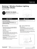
LightGrid Internal Node
Outdoor Wireless Control System
2.x Series
Installation Guide
CTRL042
FCC Statements:
Note: This equipment has been tested and found to comply with the limits
for a Class B digital device, pursuant to part 15 of the FCC Rules. These
limits are designed to provide reasonable protection against harmful
interference in a residential installation. This equipment generates, uses
and can radiate radio frequency energy and, if not installed and used in
accordance with the instructions, may cause harmful interference to radio
communications. However, there is no guarantee that interference will
not occur in a particular installation. If this equipment does cause harmful
interference to radio or television reception, which can be determined by
turning the equipment o and on, the user is encouraged to try to correct
the interference by one or more of the following measures:
• Reorient or relocate the receiving antenna.
• Increase the separation between the equipment and receiver.
• Connect the equipment into an outlet on a circuit dierent from that to
which the receiver is connected.
• Consult the dealer or an experienced radio/TV technician for help.
To satisfy FCC/ISED RF exposure requirements a separation distance of
20 cm or more must be maintained between the antenna of this device
and persons during operation. Operation at closer than 20cm is not
permitted.
CAN ICES-5 (B)/NMB-3(B)
This device complies with Industry Canada license-exempt RSS standards.
Operation is subject to the following two conditions:
• This device may not cause harmful interference, and
• This device must accept any interference received, including interference
that may cause undesired operation.
Cet appareil est conforme aux normes RSS exemptees de licence de
Industrie Canada. Son fonctionnement est soumis aux deux conditions
suivantes:
• Cet appareil ne doit pas provoquer d’interférences et
• Cet appareil doit accepter toute interférence, y compris celles pouvant
causer un mauvais fonctionnement de l’appareil.
Pour être conforme aux limites d’exposition aux ondes RF des normes
FCC/ISED, une distance de séparation d’au moins 20 cm doit être
maintenue entre l’antenne de cet appareil et toute personne pendant
son opération. Mettre en opération cet appareil a une distance plus
rapprochée que 20 cm n’est pas permis.
WARNING
RISK OF ELECTRIC SHOCK
Disconnect power before servicing or installing product.
RISK OF INJURY OR DAMAGE
Unit will fall if not installed properly. Follow installation
instructions. Install in accordance with National Electric Code
and local codes.
USE NODE ONLY WITH LED AND HID LUMINAIRES
Rated up to 1000VA. Using node with any other device may
void warranty
UNPACKING
Carefully unpack unit from its packaging. Properly inspect for
defects before installing.
CAUTION
RISK OF INJURY
Wear safety glasses and gloves during installation and servicing.
BEFORE YOU BEGIN
Read these instructions completely and carefully.

Installation GuideLightGrid Internal Node 2.x Series
2
Before Installation
Wiring the Node into a Fixture
• Carefully unpack unit. Inspect for defects before installing.
• Check Electrical parameters. Ensure that the xture operating wattage is below 1000W, and the voltage at
the xture is within the allowed range of the Controller. Using controller outside these parameters will void its
warranty.
• Validate Fixture Approval with Current. Prior to integrating the Internal Node in any xture, Current strongly
recommends validation testing of the design to ensure LightGrid performance.
Following the Wiring Diagram, perform the following steps:
• Connect the L-In (black) of the node to the line (black) of the xture.
• Connect L-Out (Red) of the node to Line of the driver
• Connect the neutral (white) of the node to the neutral (white) of the xture
• Connect the neutral (white) of the LED Driver/HID Ballast to the neutral (white) of the xture
For dimmable xture, please perform the following
extra steps:
• Connect the Dim- (grey) of the node to the negative
dimming wire of the LED Driver/HID Ballast.
• Connect the Dim+ (violet) of the node to the
positive dimming wire of the LED Driver/HID Ballast.
Required Supplies.
• LightGrid Internal Node
• Luminaire
• #10 mounting Screws of suitable type and length (recommended)
1
3
2
Wiring Diagram Incoming AC Power
Neutral Chassis
L-IN
N
L-OUT
Dim-
Dim+
ANT
COM
Chassis
Neutral
Line
Dim-
Dim+
Antenna
Unused
Lighting Fixture
LED Driver/
HID Ballast
Lightgrid
Node
Black
White
White
Black
Green
Green
Line
Red
Gray
Purple
Yellow
Brown
Black
WARNING
RISK OF DAMAGE ON NODE
Risk of damage on the node or xture if all
wiring instructions are not respected.
WIRING SET UP
All wiring setup should conform to NFPA70:
National Electrical code and CSA-22.

Installation GuideLightGrid Internal Node 2.x Series
3
Physical Integration within a Lighting Fixture
• The location of the node inside the xture must be selected to keep the node as far away as possible from sources
of heat or electrical interference, such as the lamp ballast/driver/power supply, or the light bulb or LED panel and
its heatsink. Never install the node directly above these; The preferred location is in the lower part of the xture
below any source of heat.
• Record the location the Internal Node is installed (since it doesn’t have GPS), this can be done by either manually
recording it or using the Current commissioning app that is available on iOS to ensure the node is positioned in
current location on the map view.
• Ensure the node location provides a secure and robust mounting support surface with 2 appropriately positioned
screw hole locations.
• Attach the node into the xture using 2 screws using both holes provided on opposite sides of the node.
Important Notes:
• All unused wires must be removed (cut ush with the housing) or isolated electrically (using a wire nut and/or
electrical tape or heat-shrink tubing).
• Do not attempt to open the node housing or alter any part of the node.
• It is the integrator’s responsibility to ensure the temperature rating of the node is never exceeded; Make certain
that the ambient temperature around the node in its selected location can never exceed 50 degrees Celsius.
• The node by default will be ON until schedule is downloaded to the node from the CMS.
• To select the optimum antenna mounting point, read the
following and refer to the illustrations (right) showing examples of
the best, acceptable, and unacceptable locations and orientations.
• The antenna must be mounted on a conductive (metal) surface. If the
xture is of non- conductive construction (such as plastic), the inner
surface where the antenna is to be installed should be lined with a
thin metal sheet or foil (such as copper foil tape) approximately 6” to
12” diameter, with the antenna installed through the center of this
metallized area.
• The antenna is to be installed through a 12mm diameter hole
drilled through the outer surface of the lamp xture housing. The
mounting surface around this hole must be perfectly smooth, at,
and free of any burrs to insure a watertight seal when installed.
• The antenna mounting surface thickness should be from 1mm to
6mm thick at the point where the hole is drilled.
• The antenna is not detachable from the node; A suitable location
for both the node and antenna must be found which allows the
antenna and its wire to be routed from the node installation point,
to where it can be passed through the antenna mounting hole from
the inside of the xture.
• When installing the antenna, make sure the supplied O-ring is
retained in the groove in the base ange of the antenna (on
the inner surface of the lamp housing). The plastic nut is then
threaded onto the antenna shaft on the outside of the xture and
tightened, being very careful not to overtighten. Insure the O-ring
is compressed but not displaced from its groove to prevent water
ingress.
• The antenna must be installed vertically with respect to the
ground. Therefore, the surface it is mounted to must be
horizontal. If the most suitable location is not perfectly horizontal
at the point where the antenna is mounted, bevel washers may be
used on either side of the mounting hole to insure the antenna
will be perfectly vertical when installed.
RF Antenna Location & Installation Antenna Locations
Best
Acceptable
Not Acceptable
Node Location & Installation

Installation GuideLightGrid Internal Node 2.x Series
www.gecurrent.com
© 2021 Current Lighting Solutions, LLC. All rights reserved. GE and the GE monogram are trademarks of the
General Electric Company and are used under license. Information provided is subject to change without
notice. All values are design or typical values when measured under laboratory conditions.
CTRL042 (Rev 05/18/21)
Questions
• Email: [email protected]
• Leave a Voicemail: 1-877-843-5590
• The Internal Node is supplied with 3 identical
labels. One label is axed on the node housing.
The other two labels packaged with each node are
to be axed on a visible location on the exterior
of the xture and/or the base of the pole, for
commissioning purposes.
• The MAC address of each node is printed on the
label both as barcode & plain text.
Lightgrid Internal Node Label
Non-Dimmable Fixture: To verify the installation of Lightgrid Internal Node, please follow these steps:
• Apply AC power to the xture (120- 277V, 50/60 Hz)
• If the installation has been done as per instructions in section Wiring, the light will turn o briey during the rst
60 seconds after power is applied.
Dimmable Fixture: To verify the installation of Lightgrid Internal Node, please follow these steps:
• Apply AC power to the xture (120- 277V, 50/60 Hz)
• If the dimming wires are installed as per instructions in section Wiring, the light level will visibly dim within the rst
60 seconds after power is applied and then return to full brightness.
Validation Testing
Labels
RF Antenna Location & Installation
• The selected location of the antenna on the outside of the xture must be free of any signicant conductive
(metal) obstruction horizontally, 360 degrees around it, measured from the base of the antenna where it meets
the lamp xture surface, to at least 12” above this surface. Plastic or glass features will not aect the antenna if
they are at least 1-2cm away from it.
• The preferred location for the antenna on the xture is generally the highest point on the upper surface of the
xture, centered on this mounting surface.
• On hanging xtures supported from above, the antenna may be mounted pointed downward, at a suitable
location on the lower surface of the xture housing.
-
 1
1
-
 2
2
-
 3
3
-
 4
4
dans d''autres langues
Autres documents
-
 Daintree WANSI Wireless Area Controller Guide d'installation
-
 Lightgrid Gateway Guide d'installation
-
GE Appliances CTRL044 Guide d'installation
-
Jasco 14326/ZW3006 Manuel utilisateur
-
Lumination LVR Series LED Volumetric Retrofit Kit Guide d'installation
-
Jasco 14322 Manuel utilisateur
-
GE 14291 Manuel utilisateur
-
GE 14294 Manuel utilisateur
-
INSTEON Remote Control Plug-In Lamp Dimmer Module Manuel utilisateur


