GE RARWT1B Le manuel du propriétaire
- Catégorie
- Composants de dispositif de sécurité
- Taper
- Le manuel du propriétaire

Important Safety Information .................3
Installation Instructions
........................... 4
Controls
.......................................................... 8
Controls and Operating Functions
..... 9
On Board Diagnostics
.............................. 11
Fault Codes
................................................. 12
Wiring Diagram
......................................... 13
Testing the Thermostat
..........................14
Troubleshooting
........................................ 16
Limited Warranty
...................................... 17
Consumer Support
................................... 18
49-5000400 Rev. 4
12-20 GEA
THERMOSTAT
OWNER’S MANUAL
& INSTALLATION
INSTRUCTIONS
RARWT_ _ (Single Zone Smart T.Stat)
RARMC_ _ (Smart T.Stat Ceiling Control)
RAREC1_ (RV-C or Smart T.Stat Control)
RAREC2_ (Analog or Smart T.Stat Control)
Write the model and serial numbers
here:
Model #
____________________
Serial # ____________________
You can find them on a label on the
thermostat.
GE is a trademark of the General Electric Company.
Manufactured under trademark license.
Single Zone RV

2
49-5000400 Rev. 4
THANK YOU FOR MAKING GE
APPLIANCES A PART OF YOUR RV.
Whether you grew up with GE Appliances, or this is
your first, we’re happy to have you in the family.
We take pride in the craftsmanship, innovation and
design that goes into every GE Appliances product,
and we think you will too. Among other things,
registration of your appliance ensures that we can
deliver important product information and warranty
details when you need them.

49-5000400 Rev. 4 3
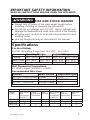
IMPORTANT SAFETY INFORMATION
READ ALL INSTRUCTIONS BEFORE USING THE APPLIANCE
WARNING
FIRE AND SHOCK HAZARD
Ŷ
Always turn off power at the main power supply before
installing, cleaning or removing the thermostat.
Ŷ
Do not use on voltages over 12 VDC. Higher voltages will
damage the thermostat and could cause shock or fire hazards.
Ŷ
All wiring must conform to local and national electrical and
building codes.
Ŷ
Use this thermostat only as described in this manual.
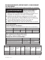
Specifications
Electrical Rating:
12 VDC (Operating Range from 10.5 VDC - 15.5 VDC)
Wall Thermostat Terminations:
0V (GND), Signal (COMMS), +12VDC
Recommended Wire Sizes:
Operating Ranges Setpoint Ranges
Cooling 60ºF–115ºF 15ºC–46ºC 60ºF–85ºF 15ºC–30ºC
Heat-Pump 25ºF–85ºF -4ºC–30ºC 40ºF–85ºF 5ºC–30ºC
Furnace See Owner’s Manual 40ºF–85ºF 5ºC–30ºC
CIRCUIT WIRE GAUGE Copper Wire Type
115 VAC Control Power 12awg SOLID
12 VDC Control Power 14awg~18awg STRANDED
12 VDC Thermostat 18awg~22awg SOLID
COMMUNICATION CONNECTIONS
Ceiling
Control
GEA Smart
Wall
Thermostat
(RARWT_ _)
5 Wire
Analog Wall
Thermostat
RV-C
Network
RV-C Room
Sensor
Compatible
(RARES1_)
Aux.
Furnace
Connection
Auto Gen
Start
Connection
RARMC2A_ X X
RAREC1A_ X X X X X
RAREC2A_ X X X X

4
49-5000400 Rev. 4
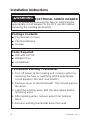
WARNING
ELECTRICAL SHOCK HAZARD
Turn off power by removing the fuse or switching the
appropriate circuit breaker to the OFF position before
removing the existing thermostat.
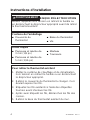
Package Contents
Ŷ
Thermostat on cover
Ŷ
Thermostat base
Ŷ
Screws
Tools Required
Ŷ
Drill with 1/8” bit
Ŷ
Ballpoint Pen
Ŷ
Screwdriver
To Remove Existing Thermostat
1. Turn off power to the heating and cooling system by
removing the fuse or switching off the appropriate
circuit breaker (115 VAC and 12VDC)
2. Remove cover of old thermostat. This should expose
the wires.
3. Label the existing wires with the wire labels before
removing wires.
4. After labeling wires, remove wires from terminal
block.
5. Remove existing thermostat base from wall.
Installation Instructions

49-5000400 Rev. 4 5
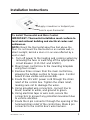
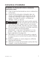
Installation Instructions
To Install Thermostat and Main Control
IMPORTANT: Thermostat installation must conform to
local and national building and electrical codes and
ordinances.
NOTE: Mount the thermostat about five feet above the
floor. Do not mount the thermostat on an outside wall, in
direct sunlight, behind a door or in an area affected by a
vent or duct.
1. Turn off power to the heating and cooling system by
removing the fuse or switching off the appropriate
circuit breaker. (115 VAC and 12VDC).
2. Mount main control box to the mounting template
using four screws.
3. Remove three screws from the main control box,
allowing the bottom section to hinge open. Control
board is now visible and accessible.
4. Route the 115 VAC power cord through the strain
relief of the control box. Tighten the strain relief,
making sure not to damage the wires.
5. Using provided wire connectors, connect line to
black, neutral to white, and ground to green.
6. Using electrical tape or wire nuts, secure the
connectors to prevent any potential movement due
to vehicle vibration.
7. Route the 6 pin connector through the opening of the
hemmed strain relief of the control box. Mate 6 pin
connector to the control box’s wire harness.
Apply screwdriver or ballpoint pen
here to open thermostat

6
49-5000400 Rev. 4
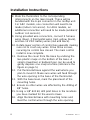
Installation Instructions
8. Mate the thermistors to the corresponding
interconnects on the main board. These will be
bundled with the 6-pin connector in the rooftop unit.
For ARC models, one connection will need to be
made (indoor coil sensor). For ARH models, an
additional connection will need to be made (ambient/
outdoor coil sensors).
9. Using provided wire connectors, connect 2 furnace
wires (blue), 3 thermostat wires (red, yellow, black),
and two 12 VDC battery wires (red and black).
10. Rotate lower section of control box upwards making
sure not to crush any wires. Drive three screws,
securing he control box closed. The main control
install is now complete.
11. Remove the cover from the base by undoing the
two plastic snaps on the bottom of the base. A
small screwdriver or ballpoint pen can be used to
gently depress one snap at a time (reference the
figure on page 5).
12. Put thermostat base against the wall where you
plan to mount it. Make sure wires will feed through
the wire opening in the base of the thermostat.
13. With the base level, mark the placement of the
mounting holes.
14 Ensure no other wires are affected by the drilling of
1/8” holes.
15. Using a 1/8” drill bit, drill pilot holes in the locations
you have marked for the wood screws.
16. Align thermostat base with mounting holes and
feed the control wires through the wire opening.

49-5000400 Rev. 4 7
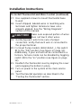
Installation Instructions
To Install Thermostat and Main Control (continued)
17.
Use supplied screws to mount thermostat base
to wall.
18. Insert stripped, labeled wires in matching wire
terminals and tighten terminal screws once
properly aligned. See the “Wiring Diagrams”
section of this manual.
CAUTION
Make sure exposed portion of wires
does not touch other wires.
19. Gently tug each wire to be sure of proper
connection. Verfiy that each wire is connected to
the proper terminal.
20. For Heat Pump models (ARH15AAC_), flip switch
#1 to the “ON” position (see figure on page 12).
Additionally, if your unit will not be connected to a
furnace, furnace mode can be disabled by toggling
switch #4 to the “on” position (see figure on page
12).
21. Reattach the thermostat cover by aligning the cover
and snapping the bottom in place.
22. Turn on power to the system at the main service
panel.
23. Test thermostat operation as described in the
“Testing the thermostat” section.

8
49-5000400 Rev. 4
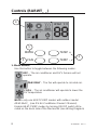
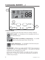
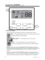
Controls (RARWT_ _)
1
2
4
MODE
FAN
TEMP +
TEMP -
3
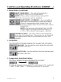
1. Mode Button
Use this button to toggle between the following modes.
OFF – The air conditioner and RV’s furnace will not
operate.
FAN ONLY – The fan will operate to circulate air.
COOL – The air conditioner will operate to lower the
RV temperature
NOTE: only use HEAT-PUMP modes with outdoor model
ARH15AAC_ (see RV Air-Conditioner Owner’s Manual).
Enable HEAT-PUMP modes by turning ON DIP switch #1 lo-
cated on the back side of the thermostat (see Wiring Diagram)

49-5000400 Rev. 4 9
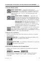
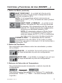
Controls and Operating Functions (RARWT_ _)
1. Mode Button (continued)
HEAT PUMP ONLY – the unit will operate the
heat-pump to raise the RV temperature.
NOTE: if the outdoor ambient drops below 25°F
(-4°C), the heat-pump will be disabled.
HEAT PUMP + FURNACE±WKHXQLWZLOO¿UVW
operate the heat-pump to conserve propane.
If the RV temperature drifts further than 3°F
from the setpoint, then the RV’s furnace will be
turned ON.
NOTE: the furnace will automatically turn ON,
if the outdoor temperature drops below 25°F
(-4°C) or if the Heat-Pump begins a defrost.
FURNACE ONLY – the RV’s furnace will operate to
raise the RV temperature. This mode can be disabled
by toggling switch #4 on the thermostat to the “ON”
position.
2. Fan Button
Use this button to toggle between fan speeds and fan modes.
FAN ON – the fan will run even when the set point
has been reached.
AUTO FAN±WKHIDQZLOOWXUQRႇRQFHWKHVHWSRLQW
has been reached.
3. Temperature Selection Buttons
Use these buttons to raise and lower the set point.
To change between Fahrenheit (°F) and Celsius (°C), hold both
“TEMP +” and “TEMP –” at the same time for 2 seconds.

10
49-5000400 Rev. 4
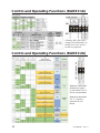
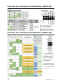
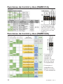
Control and Operating Functions (RAREC1A)
6ZLWFKVSHFL¿HV
default fan speed
in HP Mode if GL or
*+LVQRWVSHFL¿HG
6ZLWFKVSHFL¿HV
if a “Y” signal is
required for HP
Mode.
If Switch #5 is ON (RV-C
Virtual T.Stat Method), an
RARES1A room sensor
kit will be required.
Control and Operating Functions (RAREC2A)

49-5000400 Rev. 4 11
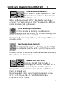
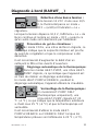
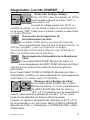
On Board Diagnostics (RARWT_ _)
Low Voltage Detection:
If the 12VDC drops below 10.5V, the
thermostat will switch to “OFF” mode
and flash “Lo”.
When voltage exceeds 10.5V, the display will show a
constant “Lo” and remain in “OFF” mode until a different
mode is reselected by the user.
A/C Freeze-Up Prevention:
In COOL mode, a flashing snowflake icon
indicates that the indoor coil is near freezing, and
that the compressor was turned off.
Recommend increasing airflow by cleaning the filter and
opening vents.
Heat-Pump Auto-Defrost:
In HEAT-PUMP modes, a flashing HEAT-PUMP
icon indicates that the unit is performing an auto-
defrost.
In HEAT-PUMP+FURNACE mode, while auto-defrosting,
the unit will use the furnace.
Heat-Pump Lockout:
In HEAT-PUMP ONLY mode, a
flashing HEAT-PUMP icon AND 25
°
F
(-4
°
C) indicates that the outdoor
temperature dropped below 25
°
F (-4
°
C) and the Heat-
Pump is locked out.
Recommended when expecting temperatures below
25
°
F (-4
°
C) to use HEAT-PUMP+FURNACE or
FURANCE ONLY mode.

12
49-5000400 Rev. 4
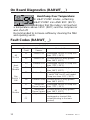
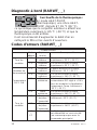
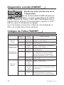
On Board Diagnostics (RARWT_ _)
Fault Codes (RARWT_ _)
Heat-Pump Over Temperature:
In HEAT-PUMP modes, a flashing
HEAT-PUMP icon AND 99
°
F (99
°
C)
indicates that the indoor coil reached
a temperature above 135
°
F (58
°
C) and the compressor
was shut off.
Recommended to increase airflow by cleaning the filter
and opening vents.
Fault Codes
Display
Code
$ႇHFWHG
Sensor
Potential Cause
All
Models
F1 Indoor Coil Unplugged Sensor or Temp less
than -22°F (-30°C)
F2 Indoor Coil Shorted wires or temp greater
than 149°F (65°C)
Heat
Pump
Models
Dip
Switch 1
ON
F3 Outdoor Coil Unplugged Sensor or Temp less
than -22°F (-30°C)
F4 Outdoor Coil Shorted wires or temp greater
than 149°F (65°C)
F5 Outdoor Temp Unplugged sensor, or Dip Switch
1 set to “ON” for AC only model.
Temp less than -22°F (-30°C)
F6 Outdoor Temp Shorted wires or temp greater
than 149°F (65°C)
All
Models
F7 Thermostat
Room Sensor
Unplugged Sensor or Temp less
than -22°F (-30°C)
F8 Thermostat
Room Sensor
Shorted wires or temp greater
than 149°F (65°C)
F9
--
FC
Signal Wire Thermostat signal wire is
unplugged or shorted (Not
communicating to the main
control)

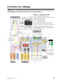
49-5000400 Rev. 4 13
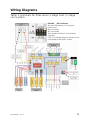
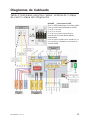
Wiring Diagrams
Table 1: terminals for three wires 1-stage heat / 1-stage
cool system.
RARWT_ _DIP Switches
#1 selects between Cool only and
Heat-Pump
#2 is not used
#3 is not used
#4 is used to disable Furnace Mode
selection.
This is for installs where a furnace is not
connected to the RVAC control.

14
49-5000400 Rev. 4
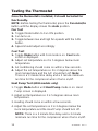
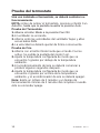
Once the thermostat is installed, it should be tested for
functionality.
NOTE: Before testing the thermostat, press the Fan Auto/On
button until the display shows the Auto position.
Fan Test
1.
Toggle Mode button to Fan ON position.
2. Fan turns on.
3. Toggle between low and high fan speeds with the FAN
button.
4.
Speed should adjust accordingly
Cool Test
1.
Toggle Mode button until Cool mode is on. Cool mode
screen is displayed.
2.
Adjust set temperature so it is 5 degrees below room
temperature.
3.
Air conditioning should come on within a few seconds.
4. Adjust the set temperature so it is 2 degrees above the
room temperature and the A/C should turn off. Note:
There is a 3 minute time delay and a 3 minute minimum
run time for the compressor when it turns on/off.
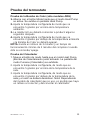
Heat Pump Test (ARH models only)
1. Toggle Mode button until Heat Pump mode is on. Heat
Pump screen is displayed.
2. Adjust set temperature so it is 5 degrees above room
temperature.
3. Heating should come on within a few seconds.
4. Adjust the set temperature so it is 2 degrees below the
room temperature and the Heat Pump should turn off.
NOTE: There is a 3 minute time delay and a 3 minute
minimum run time for the compressor when it turns on/off.
Testing the Thermostat

49-5000400 Rev. 4 15
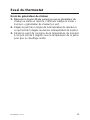
Testing the Thermostat
Furnace Test
1.
Toggle mode button until furnace mode is active. Furnace
mode screen is displayed.
2.
Adjust set temperature so it is 5 degrees above room
temperature. Within a few seconds, the furnace should initiate
its startup procedure.
3.
Adjust the set temperature so it is 2 degrees below the
room temperature and the heat should turn off. Note:
Depending on the model of furnace used, there may be a
delay in engaging and disengaging the furnace.

16
49-5000400 Rev. 4
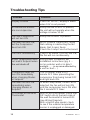
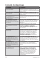
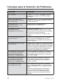
Troubleshooting Tips
Problem Solution
Display is blank Check for 12VDC; display is blank
when 12V is not present.
All thermostat buttons
are non-responsive
Verify that the 12VDC is present;
the unit will not operate when the
voltage is below 10.5V.
Fan and Compressor
will not turn ON
Verify that 115VAC is present.
Fan does not turn ON,
but the Compressor
does turn ON
WITH POWER REMOVED, verify
that nothing is obstructing the fan
blade, that it spins freely.
Check the 5 amp Fuse on the board
Fan runs continuously Check Fan Mode. If set to FAN ON,
the fan will run continuously.
Room Temperature does
not match Setpoint when
WKHXQLWVKXWVRႇ
Verify proper installation per
installation instructions (pg. 5 …
not on exterior wall or in direct
VXQOLJKW««LQDQDUHDDႇHFWHGE\
a vent or duct…)
Compressor does not
turn ON immediately
when changing Modes
or Setpoint
This is normal, there is a 3
minute OFF timer preventing the
compressor from being turned OFF
and right back ON.
Fan does not turn ON
immediately when
changing Modes or
Setpoint
In Heat-Pump mode, if Auto Fan is
selected, the fan will not turn ON
until the compressor turns ON after
the 3 minute OFF timer.
F5 Flashes on the Wall
Thermostat
With a Cool Only model, check that
DIP Switch #1 on the back side of
the wall thermostat is turned OFF.
(see Wiring Diagram)
With a Heat-Pump model, check
to see if the outdoor temperature
sensor is unplugged or damaged.

49-5000400 Rev. 4 17
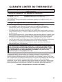
Thermostat Limited Warranty
For The Period Of: GE Appliances Will Replace:
Two Years Full Replacement of the thermostat which fails
From the date of the due to a defect in materials or workmanship.
original purchase
What GE Appliances Will Not Cover:
Ŷ
Service trips to your location.
Ŷ
Improper installation. If you have an installation problem, contact
your installer. You are responsible for providing adequate electrical
connections to the product.
Ŷ
Failure of the product resulting from modifications to the product or
due to unreasonable use, including failure to provide reasonable and
necessary maintenance.
Ŷ
In commercial locations, labor necessary to move the unit, after it has
been initially installed, to a location where it is accessible for service by
an individual technician; or, if the instructions included in this manual
have been disregarded.
Ŷ
Replacement of location fuses or the resetting of circuit breakers.
Ŷ
Damage to the product caused by improper power supply voltage,
accident, fire, floods or acts of God.
Ŷ
Incidental or consequential damage caused by possible defects with
this thermostat.
Staple your receipt here.
Proof of the original purchase date is needed to validate the warranty.
This limited warranty is extended to the original purchaser and any succeeding
owner for products purchased for use within the USA and Canada. In Alaska, the
limited warranty excludes the cost of shipping or service calls to your site.
Some states or provinces do not allow the exclusion or limitation of incidental
or consequential damages. This limited warranty gives you specific legal rights,
and you may also have other rights which vary from state to state or province
to province. To know what your legal rights are, consult your local, state or
provincial consumer affairs office or your state’s Attorney General.
Warrantor: GE Appliance, a Haier company. Louisville, KY 40225
EXCLUSION OF IMPLIED WARRANTIES—Your sole and exclusive
remedy is product exchange as provided in this Limited Warranty. Any
implied warranties, including the implied warranties of merchantability
or fitness for a particular purpose, are limited to one year or the
shortest period allowed by law.

18
49-5000400 Rev. 4
GE Appliances Website
Have a question or need assistance with your appliance? Try the GE
Appliances Website 24 hours a day, any day of the year! You can also
shop for more great GE Appliances products and take advantage of all
our on-line support services designed for your convenience. In the US:
GEAppliances.com
Register Your Appliance
Register your new appliance on-line at your convenience! Timely product
registration will allow for enhanced communication and prompt service
under the terms of your warranty, should the need arise. You may also
mail in the pre-printed registration card included in the packing material. In
the US: GEAppliances.com/register
Schedule Service
Call 1-877-540-7837 during normal business hours.
Extended Warranties
Purchase a GE Appliances extended warranty and learn about special
discounts that are available while your warranty is still in effect. You can
purchase it on-line anytime. GE Appliances Services will still be there after
your warranty expires. In the US: GEAppliances.com/extended-warranty
or call 800.626.2224 during normal business hours.
Remote Connectivity
For assistance with wireless network connectivity (for models with remote
enable),
visit our website at GEAppliances.com/connected-home-smart-
appliances or call 800.220.6899 in the US.
Parts and Accessories
Individuals qualified to service their own appliances can have parts or
accessories sent directly to their homes
(VISA, MasterCard and Discover cards are accepted). Order on-line today
24 hours every day.
In the US: GEApplianceparts.com or by phone at 877.959.8688 during
normal business hours.
Instructions contained in this manual cover procedures to be
performed by any user. Other servicing generally should be referred
to qualified service personnel. Caution must be exercised, since
improper servicing may cause unsafe operation.
Contact Us
If you are not satisfied with the service you receive from GE Appliances,
contact us on our Website with all the details including your phone
number, or write to:
General Manager, Customer Relations | GE Appliances, Appliance Park |
Louisville, KY 40225
GEAppliances.com/contact
Consumer Support

49-5000400 Rev. 4
12-20 GEA
THERMOSTAT
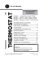
Manuel Du Propriétaire
Et Instructions
D’installation
GE est une marque déposée de General Electric
Company. Fabriqué sous licence de marque.
Écrivez le modèle et les numéros de série
ici
Modèle # ___________________
En série # __________________
Vous pouvez les trouver sur une
étiquette sur le thermostat.
Renseignements Importants
Concernant La Sécurit
...............................3
Instructions d’installation
....................... 4
Commandes
..................................................8
Commandes et fonctions de
fonctionnement
......................................... 9
Diagnostic à bord
...................................... 11
Codes d’erreurs
......................................... 12
Schémas de câblage
................................ 13
Essai du thermostat
.................................14
Conseils de dépannage
.......................... 16
Garantie Limitée
........................................ 17
Soutien au consommateur
..................... 18
Single Zone RV
RARWT_ _ (Single Zone Smart T.Stat)
RARMC_ _ (Smart T.Stat Ceiling Control)
RAREC1_ (RV-C or Smart T.Stat Control)
RAREC2_ (Analog or Smart T.Stat Control)

2
49-5000400 Rev. 4
NOUS VOUS REMERCIONS D’ACCUEILLIR GE
APPLIANCES CHEZ VOUS RV
Que vous ayez grandi avec GE Appliances ou
qu’il s’agisse de votre première acquisition, nous
sommes heureux de vous accueillir dans notre
famille.
Nous sommes fiers du savoir-faire, de l’innovation
et de l’esthétique qui composent chaque appareil
GE Appliances, et nous pensons que vous le serez
aussi. Dans cette optique, nous vous rappelons
que l’enregistrement de votre électroménager
vous assure la communication de renseignements
importants sur le produit et la garantie lorsque vous
en avez besoin.
Enregistrez votre électroménager GE en ligne dès
maintenant. Des sites Web et des numéros de
téléphone utiles figurent dans la section Soutien au
consommateur de ce manuel d’utilisation.
La page est en cours de chargement...
La page est en cours de chargement...
La page est en cours de chargement...
La page est en cours de chargement...
La page est en cours de chargement...
La page est en cours de chargement...
La page est en cours de chargement...
La page est en cours de chargement...
La page est en cours de chargement...
La page est en cours de chargement...
La page est en cours de chargement...
La page est en cours de chargement...
La page est en cours de chargement...
La page est en cours de chargement...
La page est en cours de chargement...
La page est en cours de chargement...
La page est en cours de chargement...
La page est en cours de chargement...
La page est en cours de chargement...
La page est en cours de chargement...
La page est en cours de chargement...
La page est en cours de chargement...
La page est en cours de chargement...
La page est en cours de chargement...
La page est en cours de chargement...
La page est en cours de chargement...
La page est en cours de chargement...
La page est en cours de chargement...
La page est en cours de chargement...
La page est en cours de chargement...
La page est en cours de chargement...
La page est en cours de chargement...
La page est en cours de chargement...
La page est en cours de chargement...
-
 1
1
-
 2
2
-
 3
3
-
 4
4
-
 5
5
-
 6
6
-
 7
7
-
 8
8
-
 9
9
-
 10
10
-
 11
11
-
 12
12
-
 13
13
-
 14
14
-
 15
15
-
 16
16
-
 17
17
-
 18
18
-
 19
19
-
 20
20
-
 21
21
-
 22
22
-
 23
23
-
 24
24
-
 25
25
-
 26
26
-
 27
27
-
 28
28
-
 29
29
-
 30
30
-
 31
31
-
 32
32
-
 33
33
-
 34
34
-
 35
35
-
 36
36
-
 37
37
-
 38
38
-
 39
39
-
 40
40
-
 41
41
-
 42
42
-
 43
43
-
 44
44
-
 45
45
-
 46
46
-
 47
47
-
 48
48
-
 49
49
-
 50
50
-
 51
51
-
 52
52
-
 53
53
-
 54
54


GE RARWT1B Le manuel du propriétaire
- Catégorie
- Composants de dispositif de sécurité
- Taper
- Le manuel du propriétaire
dans d''autres langues
- English: GE RARWT1B Owner's manual
- español: GE RARWT1B El manual del propietario
