Fujitsu AOU48RLXFZ1 Guide d'installation
- Taper
- Guide d'installation

EnglishFrançaisEspañol
AIR CONDITIONER
OUTDOOR UNIT
PART No. 9379069786-02
INSTALLATION MANUAL
For authorized service personnel only.
Contents
1. SAFETY PRECAUTIONS …………………………… 2
2. ABOUT THE PRODUCT
2. 1. Precautions for using R410A refrigerant ……… 4
2. 2. Special tools for R410A ………………………… 4
2. 3. Accessories ……………………………………… 4
2. 4. Optional parts …………………………………… 5
2. 5. Operating range ………………………………… 5
2. 6. System con¿ guration …………………………… 6
3. INSTALLATION WORK
3. 1. Selecting an installation location ……………… 7
3. 2. Drain installation ………………………………… 8
3. 3. Installation dimensions ………………………… 8
3. 4. Transportation of the unit …………………… 10
3. 5. Installation of the unit ………………………… 11
4. SYSTEM CONFIGURATION
4. 1. Piping limitation and Pipe size ……………… 12
5. PIPE INSTALLATION
5. 1. Opening a knockout hole …………………… 13
5. 2. Separation tube connection ………………… 14
5. 3. Flare connection (pipe connection) ………… 15
6. ELECTRICAL WIRING
6. 1. The precautions of electrical wiring ………… 17
6. 2. Knockout hole ………………………………… 18
6. 3. Electrical requirement ………………………… 18
6. 4. Unit wiring ……………………………………… 19
6. 5. Wiring method ………………………………… 20
6. 6. Connecting of wiring ………………………… 21
7. PIPE INSTALLATION II
7. 1. Sealing test …………………………………… 22
7. 2. Vaccum process ……………………………… 23
7. 3. Additional charging …………………………… 24
7. 4. Refrigerant recovery method
……………… 25
7. 5. Installing insulation …………………………… 26
7. 6. Filling with putty ……………………………… 26
8. FIELD SETTING
8. 1. Field setting switches ………………………… 27
8. 2. Function settings ……………………………… 28
9. TEST OPERATION
9. 1. Check run ……………………………………… 30
9. 2. TEST RUN …………………………………… 33
9. 3. Con¿ rming the operation of indoor unit …… 35
10. EXTERNAL INPUT & OUTPUT
10. 1. Fitting cable (option parts) …………………… 35
10. 2. External input ………………………………… 35
10. 3. External output ………………………………… 37
11. LED Display
11. 1. Normal operation mode ……………………… 38
11. 2. Error display mode …………………………… 38
9379069786-02_IM.indb 1 9/22/2016 14:08:00

En-2
1. SAFETY PRECAUTIONS
This installation manual describes how to install the outdoor unit only. To install the indoor unit, refer to the installation
manual included with the indoor unit.
IMPORTANT!
Please Read Before Starting
This air conditioning system meets strict safety and operating standards.
As the installer or service person, it is an important part of your job to
install or service the system so it operates safely and efficiently.
For safe installation and trouble-free operation, you must:
•
Carefully read this instruction booklet before beginning.
•
Follow each installation or repair step exactly as shown.
•
Observe all local, state, and national electrical codes.
•
Pay close attention to all warning, and caution notices given in this
manual.
This symbol refers to a hazard or unsafe practice which
can result in severe personal injury or death.
This symbol refers to a hazard or unsafe practice which
can result in personal injury and the potential for
product or property damage.
•
Hazard alerting symbols
Electrical
Safety / alert
If Necessary, Get Help
These instructions are all you need for most installation sites and mainte-
nance conditions. If you require help for a special problem, contact our
sales/service outlet or your certified dealer for additional instructions.
In Case of Improper Installation
The manufacturer shall in no way be responsible for improper installation
or maintenance service, including failure to follow the instructions in this
document.
SPECIAL PRECAUTIONS
When Wiring
ELECTRICAL SHOCK CAN CAUSE SEVERE PERSONAL INJURY OR
DEATH. ONLY A QUALIFIED, EXPERIENCED ELECTRICIAN SHOULD
ATTEMPT TO WIRE THIS SYSTEM.
•
Do not supply power to the unit until all wiring and tubing are completed or
reconnected and checked.
•
Highly dangerous electrical voltages are used in this system. Carefully re-
fer to the wiring diagram and these instructions when wiring. Improper con-
nections and inadequate grounding can cause accidental injury or death.
•
Ground the unit following local electrical codes.
•
Connect all wiring tightly. Loose wiring may cause overheating at connec-
tion points and a possible fire hazard.
WARNING:
CAUTION:
When Transporting
Be careful when picking up and moving the indoor and outdoor units. Get
a partner to help, and bend your knees when lifting to reduce strain on
your back. Sharp edges or thin aluminum fins on the air conditioner can
cut your fingers.
When Installing...
...In a Ceiling or Wall
Make sure the ceiling/wall is strong enough to hold the unit’s weight. It
may be necessary to construct a strong wood or metal frame to provide
added support.
...In a Room
Properly insulate any tubing run inside a room to prevent “sweating” that
can cause dripping and water damage to walls and floors.
...In Moist or Uneven Locations
Use a raised concrete pad or concrete blocks to provide a solid, level
foundation for the outdoor unit. This prevents water damage and abnor-
mal vibration.
...In an Area with High Winds
Securely anchor the outdoor unit down with bolts and a metal frame.
Provide a suitable air baffle.
...In a Snowy Area (for Heat Pump-type Systems)
Install the outdoor unit on a raised support that is higher than drifting
snow. Provide snow vents.
When Connecting Refrigerant Tubing
•
Keep all tubing runs as short as possible.
•
Use the flare method for connecting tubing.
•
•
Check carefully for leaks before starting the test run.
NOTE:
Depending on the system type, liquid and gas lines may be either narrow
or wide. Therefore, to avoid confusion the refrigerant tubing for your
particular model is specified as either “small” or “large” rather than as
“liquid” or “gas”.
When Servicing
•
Turn the power OFF at the main circuit breaker panel before opening
the unit to check or repair electrical parts and wiring.
•
Keep your fingers and clothing away from any moving parts.
•
Clean up the site after you finish, remembering to check that no metal
scraps or bits of wiring have been left inside the unit being serviced.
•
After installation, explain correct operation to the customer, using the
operating manual.
•
Apply refrigeration compressor oil (or equivalent) used for the outdoor
unit to the matching surfaces of the flare and union tubes before
connecting them, then tighten the nut with a torque wrench for a
leak-free connection.
9379069786-02_IM.indb 2 9/22/2016 14:08:03

En-3
WARNING
Never touch electrical components immediately after the power supply has been turned off. Electrical shock may
occur. After turning off the power, always wait 10 minutes or more before touching electrical components.
Do not use this equipment with air or any other unspeci¿ ed refrigerant in the refrigerant lines.
Excess pressure can cause a rupture.
During installation, make sure that the refrigerant pipe is attached ¿ rmly before you run the compressor.
Do not operate the compressor under the condition of refrigerant piping not attached properly with 2-way or 3-way
valve open.
This may cause abnormal pressure in the refrigeration cycle that leads to rupture and even injury.
Do not remove the connection pipe while the compressor is in operation with 2-way or 3-way valve open.
This may cause abnormal pressure in the refrigeration cycle that leads to rupture and even injury.
When installing and relocating the air conditioner, do not mix gases other than the speci¿ ed refrigerant (R410A) to
enter the refrigerant cycle.
If air or other gas enters the refrigerant cycle, the pressure inside the cycle will rise to an abnormally high value and
cause rupture, injury, etc.
When installing this system in high humidity locations, install using ground fault equipment breakers (often referred to
in other countries as an ELCB earth leakage current breaker) to reduce the risk of leaking current which may result in
electric shock or potential ¿ re.
This appliance is not intended for use by persons (including children) with reduced physical, sensory or mental
capabilities, or lack of experience and knowledge, unless they have been given supervision or instruction concerning
use of the appliance by a person responsible for their safety. Children should be supervised to ensure that they do
not play with the appliance.
CAUTION
For the air conditioner to operate satisfactorily, install it as outlined in this installation manual.
Connect the indoor unit and outdoor unit with the air conditioner piping and cords available standards parts.
This installation manual describes the correct connections using the installation set available from our standard parts.
Installation work must be performed in accordance with national wiring standards by authorized personnel only.
Also, do not use an extension cord.
Do not turn on the power until all installation work is complete.
Do not purge the air with refrigerants but use a vacuum pump to vacuum the installation.
There is not extra refrigerant in the outdoor unit for air purging.
Use a vacuum pump for R410A exclusively.
Using the same vacuum pump for different refrigerants may damage the vacuum pump or the unit.
Use a clean gauge manifold and charging hose for R410A exclusively.
If refrigerant leaks while work is being carried out, ventilate the area. If the refrigerant comes in contact with a À ame,
it produces a toxic gas.
• Be careful not to scratch the air conditioner when handling it.
• After installation, explain correct operation to the customer, using the operating manual.
• Let the customer keep this installation manual because it is used when the air conditioner is serviced or moved.
9379069786-02_IM.indb 3 9/22/2016 14:08:03

En-4
2. ABOUT THE PRODUCT
2. 1. Precautions for using R410A refrigerant
WARNING
The basic installation work procedures are the same as conventional refrigerant models.
However, pay careful attention to the following points:
Since the working pressure is 1.6 times higher than that of conventional refrigerant (R22) models, some of the piping
and installation and service tools are special. (See the table below.)
Especially, when replacing a conventional refrigerant (R22) model with a new refrigerant R410A model, always
replace the conventional piping and À are nuts with the R410A piping and À are nuts.
Models that use refrigerant R410A have a different charging port thread diameter to prevent erroneous charging with
conventional refrigerant (R22) and for safety. Therefore, check beforehand. [The charging port thread diameter for
R410A is 1/2 UNF 20 threads per inch.]
Be careful that foreign matter (oil, water, etc.) does not enter the piping than with refrigerant models. Also, when
storing the piping, securely seal the openings by pinching, taping, etc.
When charging the refrigerant, take into account the slight change in the composition of the gas and liquid phases.
And always charge from the liquid phase where refrigerant composition is stable.
2. 2. Special tools for R410A
Tool name Contents of change
Gauge manifold
Pressure is high and cannot be measured with a conventional (R22) gauge. To prevent
erroneous mixing of other refrigerants, the diameter of each port has been changed.
It is recommended the gauge with seals 30 in.Hg to 768 psi (–0.1 to 5.3 MPa) for high
pressure. 30 in.Hg to 551 psi (–0.1 to 3.8 MPa) for low pressure.
Charge hose To increase pressure resistance, the hose material and base size were changed.
Vacuum pump A conventional vacuum pump can be used by installing a vacuum pump adapter.
Gas leakage detector Special gas leakage detector for HFC refrigerant R410A.
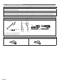
2. 3. Accessories
WARNING
For installation purposes, be sure to use the parts supplied by the manufacturer or other prescribed parts. The use
of non-prescribed parts can cause serious accidents such as the unit falling, water leakage, electric shock, or ¿ re.
Do not throw away the connecting parts until the installation has been complete.
Name and shape Q’ty Application Name and shape Q’ty Application
Installation
manual
1
(This book) Binder
3
For binding power supply
cable and connection
cable
Drain cap
7
For outdoor unit drain piping
work
Conduit plate
1
To ¿ x Conduit tube
Drain pipe
1
For outdoor unit drain piping
work
9379069786-02_IM.indb 4 9/22/2016 14:08:03

En-5
2. 4. Optional parts
CAUTION
The following parts are optional parts speci¿ c to R410A refrigerant.
Do not use parts other than those listed below.
Refer to the installation manual for the Branch box and the Separation tubes.
Parts name Model name
Separation tube UTP-SX248A
Branch box
Primary UTP-PU03A
Secondary UTP-PU03B
External connect kit
(for External input/output)
UTY-XWZXZ3
External connect kit
(for Base heater)
UTY-XWZXZ4
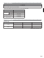
2. 5. Operating range
Operating range
Temperature Indoor air intake Outdoor air intake
Cooling
Maximum 90 °F DB 115 °F DB
Minimum 64 °F DB 23 °F DB
Heating
Maximum 88 °F DB 75 °F DB
Minimum 60 °F DB 5 °F DB
Indoor humidity about 80% or less
9379069786-02_IM.indb 5 9/22/2016 14:08:04

En-6
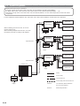
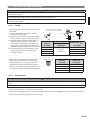
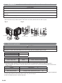
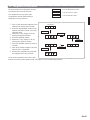
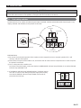
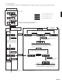
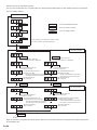
2. 6. System con¿ guration
• 2 to 8 indoor units can be connected.
• The total capacity of the indoor units connected must be between 38,400 and 62,400BTU.
Ex. Eight indoor units: 7,000+7,000+7,000+7,000+7,000+7,000+7,000+12,000=61,000BTU ĺ OK
• If the total capacity of the connected indoor units exceeds 62,400BTU, an error will be displayed and the units will be
not operate.
For the installation method of Branch box and indoor units, refer to the installation manuals that come with them.
When installing just 1 branch box, be sure to
use the primary unit.
When installing multiple branch boxes, use both
the primary unit and secondary units together.
Breaker2 Circuit breaker (MOCP:Maximum
Over Current Protection)
Breaker1 Earth leakage breaker
Branch box
(Secondary2)
Breaker2
Breaker2
Breaker2
Breaker2
Breaker1
Breaker1
Breaker1
Breaker1
Indoor unit
Indoor unit
Indoor unit
Indoor unit
Indoor unit
Indoor unit
Indoor unit
Indoor unit
Separation tube
Separation tube
Outdoor unit
Piping
Power supply
Transmission line
Power supply and Transmission line
Power
supply
Power
supply
Power
supply
Power supply
Branch box
(Primary)
Branch box
(Secondary1)
9379069786-02_IM.indb 6 9/22/2016 14:08:04

En-7
3. INSTALLATION WORK
Please obtain the approval of the customer when selecting the location of installation and installing the unit.
3. 1. Selecting an installation location
WARNING
Securely install the outdoor unit at a location that can withstand the weight of the unit. Otherwise, the outdoor unit
may fall and cause injury.
Be sure to install the outdoor unit as prescribed, so that it can withstand earthquakes and typhoons or other strong
winds. Improper installation can cause the unit to topple or fall, or other accidents.
Do not install the outdoor unit near the edge of a balcony. Otherwise, children may climb onto the outdoor unit and
fall off of the balcony.
CAUTION
Do not install the outdoor unit in the following areas:
• Area with high salt content, such as at the seaside. It will deteriorate metal parts, causing the parts to fail or the
unit to leak water.
• Area ¿ lled with mineral oil or containing a large amount of splashed oil or steam, such as a kitchen. It will
deteriorate plastic parts, causing the parts to fail or the unit to leak water.
• Area that generates substances that adversely affect the equipment, such as sulfuric gas, chlorine gas, acid, or
alkali. It will cause the copper pipes and brazed joints to corrode, which can cause refrigerant leakage.
• Area containing equipment that generates electromagnetic interference. It will cause the control system to
malfunction, preventing the unit from operating normally.
• Area that can cause combustible gas to leak, contains suspended carbon ¿ bers or À ammable dust, or volatile
inÀ ammables such as paint thinner or gasoline. If gas leaks and settles around the unit, it can cause a ¿ re.
• Area that has heat sources, vapors, or the risk of the leakage of À ammable gas in the vicinity.
• Area where small animals may live. It may cause failure, smoke or ¿ re if small animals enter and touch internal
electrical parts.
• Area where animals may urinate on the unit or ammonia may be generated.
Please install the outdoor unit without slant.
Install the outdoor unit in a well-ventilated location away from rain or direct sunlight.
If the outdoor unit must be installed in an area within easy reach of the general public, install as necessary a
protective fence or the like to prevent their access.
Install the outdoor unit in a location that would not inconvenience your neighbors, as they could be affected by the
airÀ ow coming out from the outlet, noise, or vibration. If it must be installed in proximity to your neighbors, be sure
to obtain their approval.
If the outdoor unit is installed in a cold region that is affected by snow accumulation, snow fall, or freezing, take
appropriate measures to protect it from those elements. To ensure a stable operation, install inlet and outlet ducts.
Install the outdoor unit in a location that is away from exhaust or the vent ports that discharge vapor, soot, dust, or
debris.
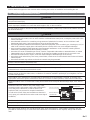
Install the indoor unit, outdoor unit, power supply cable,
connection cable, and remote control cable at least 40 in.
(1 m) away from a television or radio receivers. The
purpose of this is to prevent TV reception interference
or radio noise. (Even if they are installed more than 40 in.
(1 m) apart, you could still receive noise under some signal
conditions.)
Branch switch and
circuit breaker
40 in. (1 m) or more
40 in. (1 m) or more
Branch switch and
circuit breaker
If children under 10 years old may approach the unit, take preventive measures so that they cannot reach the unit.
Keep the length of the piping of the indoor and outdoor units within the allowable range.
For maintenance purposes, do not bury the piping.
All Fujitsu General products are manufactured to metric units and tolerances. United States customary units are
provided for reference only. In cases where exact dimensions and tolerances are required, always refer to metric
units.
9379069786-02_IM.indb 7 9/22/2016 14:08:04

En-8
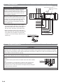
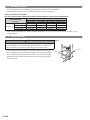
3. 2. Drain installation
CAUTION
Perform drain work in accordance with this
Manual, and ensure that the drain water is
properly drained. If the drain work is not carried
out correctly, water may drip down from the
unit, wetting the furniture.
When the outdoor temperature is 32 °F (0 °C)
or less, do not use the accessory drain pipe
and drain cap. If the drain pipe and drain cap
are used, the drain water in the pipe may
freeze in extremely cold weather. (Reverse
cycle model only).
• As the drain water À ows out of the outdoor
unit during heating operation, install the drain
pipe and connect it to a commercial 5/8 in.
(16 mm) hose. (Reverse cycle model only)
• When installing the drain pipe, plug all the
holes other than the drain pipe mounting hole
in the bottom of the outdoor unit with putty
so there is no water leakage. (Reverse cycle
model only)
3. 3. Installation dimensions
CAUTION
The installation space shown in the following examples is based on an ambient temperature under cooling
operation of 95 °F (DB) (35 °C DB) at the air intake of the outdoor unit. Provide more space around the air intake
than shown in the examples if the ambient temperature exceeds 95 °F (DB) (35 °C DB) or if the thermal load of all
of the outdoor units exceeds the capacity.
Consider the transportation route, installation space, maintenance space, and access, and install the unit in a
location with suf¿ cient space for the refrigerant piping.
Observe the installation space speci¿ cations that are shown in the
¿ gures.
Provide the same space for the air intake at the rear of the outdoor
unit.
If the installation is not performed according to the speci¿ cations,
it could cause a short circuit and result in a lack of operating
performance. As a result, the outdoor unit might easily be stopped
by high-pressure protection.
Air intake
Rear view
Installation methods not shown in the following examples are not recommended. Performance may drop signi¿ cantly.
Base
Drain pipe
Drain pipe mounting hole
(Unit: in. (mm))
Drain pipe mounting
hole
1-9/16 (40)
1-31/32 (50)
3 (76)
10-15/16 (278)
17-1/4 (438)
20-23/32 (526)
24-1/2 (622)
27-5/32 (690)
5-1/2 (140)
8-15/16 (227)
11-21/32 (296)
12 (305)
12-13/32 (315)
12-5/8 (321)
13-7/16 (341)
Drain cap mounting hole
9379069786-02_IM.indb 8 9/22/2016 14:08:05

En-9
3. 3. 1. Single outdoor unit installation
When the upper space is open [Unit: in. (mm)]
(1) Obstacles at the rear
only
(2) Obstacles at rear and
sides
(3) Obstacles at the front
only
(4) Obstacles at the front
and rear
39-3/8 (1000) or more
7-7/8 (200)
or more
11-13/16 (300)
or more
7-7/8 (200)
or more
39-3/8 (1000) more
5-7/8 (150)
or more
5-7/8 (150)
or more
When there is an obstruction in the upper space: [Unit: in. (mm)]
(1) Obstacles at the rear and above
11-13/16 (300)
or more
Max. 19-11/16 (500)
39-3/8 (1000)
or more
(2) Obstacles at the rear, sides, and above
39-3/8 (1000)
or more
19-11/16 (500)
or more
7-7/8 (200)
or more
Max. 19-11/16 (500)
9-13/16 (250)
or more
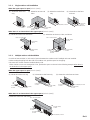
3. 3. 2. Multiple outdoor unit installation
• Provide at least 9-13/16 in. (250 mm) of space between the outdoor units if multiple units are installed.
• When routing the piping from the side of an outdoor unit, provide space for the piping.
• No more than 3 units must be installed side by side.
When 3 units or more are arranged in a line, provide the space as shown in the following example when there is
an obstruction in the upper space:
When the upper space is open [Unit: in. (mm)]
(1) Obstacles at the rear only
9-13/16 (250)
or more
11-13/16 (300)
or more
(2) Obstacles at the front only
9-13/16 (250)
or more
59-1/16 (1500)
or more
(3) Obstacles at the front and rear
9-13/16 (250)
or more
19-11/16 (500) or more
59-1/16 (1500)
or more
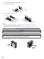
When there is an obstruction in the upper space: [Unit: in. (mm)]
• Obstacles at the rear and above
59-1/16 (1500)
or more
59-1/16 (1500)
or more
19-11/16 (500) or more
Max. 11-13/16 (300)
9-13/16 (250)
or more
9379069786-02_IM.indb 9 9/22/2016 14:08:05

En-10
3. 3. 3. Outdoor units installation in multi-row [Unit: in. (mm)]
(1) Single parallel unit arrangement
19-11/16 (500) or more
23-5/8 (600) or more
39-3/8 (1500) or more
118-1/8 (3000) or more
(2) Multiple parallel unit arrangement
9-13/16 (250)
or more
9-13/16 (250)
or more
19-11/16 (500)
or more
118-1/8 (3000) or more
23-5/8 (600) or more
59-1/16 (1500) or more
9-13/16 (250)
or more
59-1/16 (1500)
or more
19-11/16 (500)
or more
NOTES:
• If the space is larger than stated above, the condition will be the same as when there is no obstacle.
• Height above the À oor level should be 50 mm or more.
• When installing the outdoor unit, be sure to open the front and left side to obtain better operation ef¿ ciency.
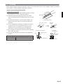
3. 4. Transportation of the unit
WARNING
Do not touch the ¿ ns. Otherwise, personal injury could result.
CAUTION
When carrying the unit, hold the handles on the right and left sides and be careful.
If the outdoor unit is carried from the bottom, hands or ¿ ngers may be pinched.
• Be sure to hold the handles on the sides of the unit. Otherwise, holding the suction grille on the sides of the unit
may cause deformation.
Handle
Handle
Handle
Suction grille
9379069786-02_IM.indb 10 9/22/2016 14:08:05

En-11
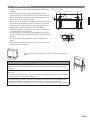
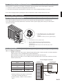
3. 5. Installation of the unit
• Install 4 anchor bolts at the locations indicated with arrows in
the ¿ gure.
• To reduce vibration, do not install the unit directly on the
ground. Install it on a secure base (such as concrete blocks).
• The foundation shall support the legs of the unit and have a
width of 1-31/32 in. (50 mm) or more.
• Depending on the installation conditions, the outdoor unit may
spread its vibration during operation, which may cause noise
and vibration. Therefore, attach damping materials (such as
damping pads) to the outdoor unit during installation.
• Install the foundation, making sure that there is enough space
for installing the connection pipes.
• Secure the unit to a solid block using foundation bolts. (Use
4 sets of commercially available M10 (3/8 in.) bolts, nuts, and
washers.)
• The bolts should protrude 25/32 in. (20 mm). (Refer to the
¿ gure.)
• If overturning prevention is required, purchase the necessary
commercially available items.
(Unit : in. (mm))
6-17/32 (166)
AIR
25-19/32 (650)
6-1/16 (154)
1-31/32 (50) 1-31/32 (50)
5/8 (16)
16-5/32 (410)
Bolt
25/32 (20)
Nut
Base
• Do not install directly on the ground, this may result in equipment
failure.
2” (5 cm) or over
CAUTION
Do not install the outdoor unit in two-stage where the drain water could freeze.
Otherwise the drainage from the upper unit may form ice and cause a malfunction of the
lower unit.
When the outdoor temperature is 0 °C or less, do not use the accessory drain pipe and
drain cap.
If the drain pipe and drain cap are used, the drain water in the pipe may freeze in extremely
cold climate. (For reverse cycle model only.)
In area with heavy snowfall, if the inlet and outlet of the outdoor unit is blocked with snow,
it might become dif¿ cult to get warm, and it is likely to cause product malfunction.
Construct a canopy and a pedestal, or place the unit on a high stand that is locally installed.
9379069786-02_IM.indb 11 9/22/2016 14:08:05

En-12
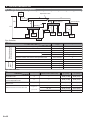
4. SYSTEM CONFIGURATION
4. 1. Piping limitation and Pipe size
H1
a
Outdoor
Unit
b
c
d
e
Branch Box
f
h
g
i
k
j
l
m
H2
H3
H
4
Indoor
Unit1
Indoor
Unit2
Branch Box
Branch Box
Separation Tube
(Primary)
(Secondary1)
(Secondary2)
Indoor
Unit3
Indoor
Unit4
Indoor
Unit5
Indoor
Unit6
Indoor
Unit7
Indoor
Unit8
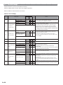
Pipe limitation
Limitation
ft (m)
Diagram
Allowable pipe length
(actual pipe length)
Maximum total equivalent pipe length Total
Between outdoor unit and the farthest indoor unit a + b + c + m
Between outdoor unit and branch boxes a + b + c + d + e
Between branch box and indoor unit
Total f + g + h + i + j + k + l + m
Each unit f, g, h, i, j, k, l, m
Between outdoor unit and the first separation tube
Between outdoor unit and branch box (when there is no separation tube㧕
a
Allowable
height
difference
Between outdoor unit and indoor unit
H1
Between outdoor unit and branch box
H2
Between branch box and branch box
H3
Between indoor unit and indoor unit
377 or less (115)
230 or less (70)
180 or less (55)
197 or less (60)
Between 10-49 (3-15)
16 or more (5)
98 or less (30)
98 or less (30)
49 or less (15)
49 or less (15)
16 or more (5)
H4
a+d
Pipe size selection
Liquid pipe
(in. (mm))
䇭䇭䇭䇭䇭
a
䇭
―
䇭䇭䇭䇭䇭䇭䇭
Φ5/8 (15.88) Φ3/8 (9.52)
c, d, e
Φ5/8 (15.88) Φ3/8 (9.52)
Diagram
Condition
f, g, h, i,
j, k, l, m
7 ,9, 12 Φ3/8 (9.52) Φ1/4 (6.35)
Φ1/2 (12.70)
䇭
Φ
1/4 (6.35)
Φ5/8 (15.88) Φ3/8 (9.52)
Between outdoor unit and first
separation tube
Between first separation tube and
second separation tube
b
Between separation tube and
branch box
Between branch box and indoor unit
Gas pipe
(in. (mm))
(Model code of indoor unit)
15, 18
24
Φ5/8 (15.88) Φ1/4 (6.35)
9379069786-02_IM.indb 12 9/22/2016 14:08:06

En-13
Pipe material
Pipe outside diameter
(in. (mm))
1/4 (6.35)
3/8 (9.52)
1/2 (12.70)
5/8 (15.88)
3/4 (19.05)
Thickness
(in. (mm))
0.032 (0.80)
0.032 (0.80)
0.032 (0.80)
0.039 (1.00)
0.047 (1.20)
Thicknesses of Annealed Copper Pipes (R410A)
* JIS H3300 C1220T-O or equivalent
*
Please select the pipe size in accordance with local rules.
It is necessary to use seamless copper pipes and it is
desirable that the amount of residual oil is less than
0.00025 lbs./100 ft. (40 mg/10 m). Do not use copper
pipes having a collapsed, deformed or discolored
portion (especially on the interior surface). Otherwise,
the expansion valve or capillary tube may become
blocked with contaminants.
As an air conditioner using R410A incurs pressure
higher than when using conventional refrigerant (R22),
it is necessary to choose adequate materials.
Thicknesses of copper pipes used with R410A are as
shown in the table. Never use copper pipes thinner
than that in the table even when it is available on the
market.
5. PIPE INSTALLATION
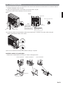
5. 1. Opening a knockout hole
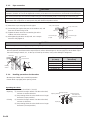
CAUTION
Be careful not to deform or scratch the panel while opening the knockout holes.
To protect the piping insulation after opening a knockout hole, remove any burrs from the edge of the hole. It is
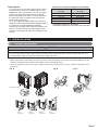
recommended to apply rust prevention paint to the edge of the hole.
• Pipes can be connected from 4 directions, front, lateral side, rear side and bottom. (Fig. A)
• When connecting at the bottom, remove the service panel and piping cover on the front of the outdoor unit, and
open the knockout hole provided at the bottom corner of the piping outlet.
• It can be installed as shown on “Fig. B” cutting out the 2 slits as indicated on “Fig. C”. (When cutting slits, use a
steel saw.)
Service panel
Fig. A
Bottom
connection
Slit
Slit
Fig. B Fig. C
Front
connection
Bottom
connection
Lateral
connection
Rear
connection
9379069786-02_IM.indb 13 9/22/2016 14:08:06

En-14
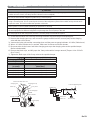
5. 2. Separation tube connection
CAUTION
Use genuine separation tubes for the refrigerant piping branches. Separation tubes may be used for piping between
the outdoor unit and branch box.
Select number of separation tubes and purchase it before starting the installation work.
Any vertical piping shall be in the part of the main piping. If a main pipe is bent, keep the straight part more than 10 times
the diameter of the connected pipe. A variance in the amount of refrigerant may be caused if the straight part is short.
For details, refer to the Installation Manual of separation tubes.
CAUTION
Separation tube
A
B
A
B
A
B
Horizontal
line
OK
Horizontal
Vertical
or
NO GOOD
±15°
A : Outdoor unit or Separation tube
B : Branch box or Separation tube
Name and shape
Liquid pipe
Gas pipe
9379069786-02_IM.indb 14 9/22/2016 14:08:06

En-15
5. 3. Flare connection (pipe connection)
CAUTION
Do not use mineral oil on a À ared part. Prevent mineral oil from getting into the system as this would reduce the
lifetime of the units.
While welding the pipes, be sure to blow dry nitrogen gas through them.
The maximum lengths of this product are shown in the table. If the units are further apart than this, correct operation
cannot be guaranteed.
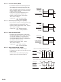
5. 3. 1. Flaring
• Use special pipe cutter and À are tool exclusive
for R410A.
(1) Cut the connection pipe to the necessary
length with a pipe cutter.
(2) Hold the pipe downward so that the cuttings
will not enter the pipe and remove any burrs.
(3)
Insert the À are nut (always use the À are nut
attached to the indoor and outdoor units
respectively) onto the pipe and perform the
À are processing with a À are tool. Leakage of
refrigerant may result if other À are nuts are used.
(4) Protect the pipes by pinching them or with
tape to prevent dust, dirt, or water from
entering the pipes.
Check if [L] is À ared uniformly
and is not cracked or scratched.
B
L
Pipe
A
Die
Pipe outside
diameter
[
in. (mm)
]
Dimension A (in. (mm))
Dimension B
0
- 0.4
[
in. (mm)
]
Flare tool for R410A,
clutch type
1/4 (6.35)
0 to 0.02
(0 to 0.5)
11/32 (9.1)
3/8 (9.52) 17/32 (13.2)
1/2 (12.70) 21/32 (16.6)
5/8 (15.88) 25/32 (19.7)
• When using conventional À are tools to À are
R410A pipes, the dimension A should be
approximately 0.02 in. (0.5 mm) more than
indicated in the table (for À aring with R410A
À are tools) to achieve the speci¿ ed À aring. Use
a thickness gauge to measure the dimension A.
Pipe outside
diameter
[
in. (mm)
]
Width across À ats
of Flare nut
[
in. (mm)
]
1/4 (6.35) 21/32 (17)
3/8 (9.52) 7/8 (22)
1/2 (12.70) 1-1/32 (26)
5/8 (15.88) 1-5/32 (29)
Width across À ats
5. 3. 2. Bending pipes
CAUTION
To prevent breaking of the pipe, avoid sharp bends. Bend the pipe with a radius of curvature of 4 in. (100 mm) or
more.
If the pipe is bent repeatedly at the same place, it will break.
• If pipes are shaped by hand, be careful not to collapse them.
• Do not bend the pipes at an angle of more than 90°.
• When pipes are repeatedly bent or stretched, the material will harden, making it dif¿ cult to bend or stretch them any more.
• Do not bend or stretch the pipes more than 3 times.
9379069786-02_IM.indb 15 9/22/2016 14:08:07

En-16
5. 3. 3. Pipe connection
CAUTION
Be sure to install the pipe against the port on the indoor unit and the outdoor unit correctly. If the centering is
improper, the À are nut cannot be tightened smoothly. If the À are nut is forced to turn, the threads will be damaged.
Do not remove the À are nut from the outdoor unit pipe until immediately before connecting the connection pipe.
After installing the piping, make sure that the connection pipes do not touch the compressor or outer panel. If the
pipes touch the compressor or outer panel, they will vibrate and produce noise.
(1) Detach the caps and plugs from the pipes.
(2) Center the pipe against the port on the outdoor unit, and
then turn the À are nut by hand.
(3) Tighten the À are nut of the connection pipe at the
outdoor unit valve connector.
(4)
After tightening the À are nut by hand, use a torque
wrench to fully tighten it.
3-way valve (Liquid)
3-way valve (Gas)
Flare nut
Connection pipe
(Liquid)
Flare nut
Connection pipe
(Gas)
CAUTION
Hold the torque wrench at its grip, keeping it in a right angle with the pipe, in order to tighten the À are nut correctly.
• Outer panel may be distorted if fastened only with a wrench. Be sure to ¿ x the elementary part with a holding
wrench (spanner) and fasten with a torque wrench (refer to below diagram).
Do not apply force to the blank cap of
the valve or hang a wrench, etc., on the cap. If blank cap is broken, it may cause leakage of refrigerant.
90°
Blank cap
Flare nut
Torque wrench
Holding
wrench
Torque wrench
Flare nut
[in. (mm)]
Tightening torque
[lbf·ft (N·m)]
1/4 (6.35) dia.
11.8 to 13.3 (16 to 18)
3/8 (9.52) dia.
23.6 to 31.0 (32 to 42)
1/2 (12.70) dia.
36.1 to 45.0 (49 to 61)
5/8 (15.88) dia.
46.5 to 55.3 (63 to 75)
3/4 (19.05) dia.
66.4 to 81.1 (90 to 110)
5. 3. 4. Handling precautions for the valves
• Mounted part of Blank cap is sealed for protection.
• Fasten blank cap tightly after opening valves.
Operating the valves
• Use a hexagon wrench (size 5/32 in. (4 mm)).
• Opening (1) Insert the hexagon wrench into the valve shaft,
and turn it counterclockwise.
(2) Stop turning when the valve shaft can no longer
be turned. (Open position)
• Closing (1) Insert the hexagon wrench into the valve shaft,
and turn it clockwise.
(2) Stop turning when the valve shaft can no longer
be turned. (Closed position)
Opening direction
Hexagon wrench
Seal (blank cap
installation portion)
Liquid pipe
Gas pipe
Opening direction
9379069786-02_IM.indb 16 9/22/2016 14:08:07

En-17
6. ELECTRICAL WIRING
6. 1. The precautions of electrical wiring
WARNING
Wiring connections must be performed by a quali¿ ed person in accordance with speci¿ cations.
The rated supply of this product is 60Hz, 208/230V. Use a voltage within the range of 187-264V.
Before connecting the wires, make sure the power supply is OFF.
When installing this system in high humidity locations, install using ground fault equipment breakers (often referred
to in other countries as an ELCB earth leakage current breaker) to reduce the risk of leaking current which may
result in electric shock or potential ¿ re.
Be sure to install a breaker of the speci¿ ed capacity. When selecting breaker, please comply with the laws and the
regulations of each country. One breaker must be installed on the power supply of the outdoor unit. Wrong selection
and setup of the breaker will cause electric shock or ¿ re.
Do not connect AC power supply to the transmission line terminal board.
Improper wiring can damage the entire system.
Connect the connector cord securely to the terminal.
Faulty installation can cause a ¿ re.
Make sure to secure the insulation portion of the connector cable with the cord clamp. A damaged insulation can
cause a short circuit.
Never install a power factor improvement condenser. Instead of improving the power factor, the condenser may
overheat.
Before servicing the unit, turn the power supply switch OFF. Then, do not touch electric parts for 10 minutes due to
the risk of electric shock.
Make sure to perform grounding work. Improper grounding work can cause electric shocks.
CAUTION
The primary power supply capacity is for the air conditioner itself, and does not include the concurrent use of other
devices.
Do not use crossover power supply wiring for the outdoor unit.
If the electrical power is inadequate, contact your electric power company.
Install a breaker in a location that is not exposed to high temperatures.
If the temperature surrounding the breaker is too high, the amperage at which the breaker cuts out may decrease.
We suggest installing GFEB breakers or follow local electrical code. This system uses an inverter, which means that
when used with a ground fault breaker you must use breakers that can handle higher harmonics such as a (GFEB)
Ground Fault Equipment Breaker (30 mA or greater) in order to prevent malfunctioning of ground fault device.
When the electrical switchboard is installed outdoors, place it under lock and key so that it is not easily accessible.
Do not fasten the power supply cable and connection cable together.
Always keep to the maximum length of the connection cable. Exceeding the maximum length may lead to
erroneous operation.
The static electricity that is charged to the human body can damage the control PC Board when handling the
control PC Board for address setting, etc.
Please keep caution to the following points.
Provide the grounding of Indoor unit, Outdoor unit and Option equipment.
Cut off the power supply (breaker).
Touch the metal section (such as the unpainted control box section) of the indoor or outdoor unit for more than 10
seconds. Discharge the static electricity in your body.
Never touch the component terminal or pattern on the PC Board.
9379069786-02_IM.indb 17 9/22/2016 14:08:07

En-18
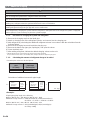
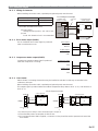
6. 2. Knockout hole
CAUTION
Be careful not to deform or scratch the panel while opening the knockout holes.
When cables are routed from the unit, a protection sleeve for the conduits can be inserted at the knockout hole.
If you do not use a wire conduit, be sure to protect the wires to prevent the edge of the knockout hole from cutting
the wires.
It is recommended to apply anti-rust paint to the edge of the knockout hole.
• Knock out holes are provided for wiring. (Fig. A)
• Knock out holes are provided 2 each in the same size in front, lateral and rear sides. (Fig. B)
Fig. A Fig. B
Service panel
Front connection Lateral connection Rear connection
6. 3. Electrical requirement
CAUTION
Be sure to install a breaker of the speci¿ ed capacity.
Regulation of cables and breaker differs from each locality, refer in accordance with local rules.
Voltage rating 1ĭ 208/230V (60Hz)
Operating range 187-264V
Cable Cable size *
1)
Remarks
Power supply cable 8AWG 2 cable + Ground, 1 Ø 208/230V
Connection cable 14AWG 3 cable + Ground, 1 Ø 208/230V
1) Selected sample: Select the correct cable type and size according to the country or region’s regulations.
Max. wire length: Set a length so that the voltage drop is less than 2%. Increase the wire diameter when the wire
length is long.
Breaker Speci¿ cation *
2)
Circuit breaker (MOCP) *4) Current : 40 (A)
Earth leakage breaker Leakage current : 30mA 0.1sec or less *3)
2) Select the appropriate breaker of the described speci¿ cation according to the national or regional standards.
3) Select the breaker that enough load current can pass through it.
4) MOCP: Maximum Over Current Protection
9379069786-02_IM.indb 18 9/22/2016 14:08:07

En-19
6. 4. Unit wiring
• When stripping off the coating of a lead wire, always use a special tool such as a wire stripper. If there is no special
tool available, carefully strip the coating with a knife etc.
How to connect wiring to the terminal
Caution when wiring cable
(1) Use ring type terminals with insulating sleeves as shown
in the ¿ gure to connect to the terminal block.
(2) Securely clamp the ring type terminals to the wires
using an appropriate tool so that the wires do not come
loose.
(3) Use the speci¿ ed wires, connect them securely, and
fasten them so that there is no stress placed on the
terminals.
(4) Use an appropriate screwdriver to tighten the terminal
screws. Do not use a screwdriver that is too small,
otherwise, the screw heads may be damaged and
prevent the screws from being properly tightened.
(5) Do not tighten the terminal screws too much, otherwise,
the screws may break.
(6) See the table below for the terminal screw tightening
torques.
Tightening torque [lbf·in. (N·m)]
M4 screw 11 to 16 (1.2 to 1.8)
M5 screw 17 to 25 (2.0 to 3.0)
Power supply cable
1-3/16 in. (30 mm)
1-3/8 in. (35 mm)
Earth cable
Sleeve
Strip : 3/8 in. (10 mm)
Ring type
terminal
Wire
Screw with special washer
Ring type terminal
Terminal blocks
Screw with
special washer
Wire
Ring type
terminal
9379069786-02_IM.indb 19 9/22/2016 14:08:08

En-20
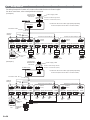
6. 5. Wiring method
The wiring example for Outdoor unit, Indoor units and Branch box is shown in ¿ gure.
For other connections, refer to Design&Technical Manual.
̪ Select the disconnect switch appropriately depending
on the loads (total current value of connected units).
̪ Select the disconnect switch appropriately depending
on the loads (total current value of connected units).
123
Single-phase
208/230V 60Hz
Max.26.5A
BRANCH BOX
Power supply cable
Breaker1
POWER
Breaker2
Breaker1: Eeath leakage breaker
Breaker2: Circuit breaker (MOCP)
Outdoor unit
123
Single-phase
208/230V 60Hz
Max.26.5A
BRANCH BOX
Power supply cable
Breaker1
POWER
Breaker2
Breaker1: Eeath leakage breaker
Breaker2: Circuit breaker (MOCP)
Outdoor unit
123 123 123
123
123
123
123
123
123
123
123
123 123
123
123
123
123 123
Single-phase
208/230V
60Hz
Branch
box
(Primary)
Branch box (Secondary1) Branch box (Secondary2)
Indoor
unit
Indoor
unit
Indoor
unit
Indoor
unit
Indoor
unit
Indoor
unit
unit
Indoor
unit
OUTDOOR UNIT
INDOOR UNIT A INDOOR UNIT B INDOOR UNIT C
Indoor
Disconnect
switch
POWER
REMOTE
CONTROL
BRANCH BOX
INDOOR UNIT A INDOOR UNIT B INDOOR UNIT C
REMOTE
CONTROL
INDOOR UNIT A INDOOR UNIT B INDOOR UNIT C
REMOTE
CONTROL
BRANCH BOX
BRANCH BOX
Optional
terminal
(Optional
terminal)
BRANCH BOX1
BRANCH BOX2
Breaker2
Breaker1
Single-phase
208/230V
60Hz
POWER
Breaker2
Breaker1
Single-phase
208/230V
60Hz
POWER
Breaker2
Breaker1
(Optional
terminal)
123 123 123
123
123
123
123
123
123
123
123
123 123
123
123
123
123 123
Single-phase
208/230V
60Hz
Branch
box
(Primary)
Branch box (Secondary1) Branch box (Secondary2)
Indoor
unit
Indoor
unit
Indoor
unit
Indoor
unit
Indoor
unit
Indoor
unit
unit
Indoor
unit
OUTDOOR UNIT
INDOOR UNIT A INDOOR UNIT B INDOOR UNIT C
Indoor
Disconnect
switch
POWER
REMOTE
CONTROL
BRANCH BOX
INDOOR UNIT A INDOOR UNIT B INDOOR UNIT C
REMOTE
CONTROL
INDOOR UNIT A INDOOR UNIT B INDOOR UNIT C
REMOTE
CONTROL
BRANCH BOX
BRANCH BOX
Optional
terminal
(Optional
terminal)
BRANCH BOX1
BRANCH BOX2
Breaker1
POWER POWER
(Optional
terminal)
Breaker2
Connection cable
Connection cable
[Example 1]
[Example 2]
Junction box
9379069786-02_IM.indb 20 9/22/2016 14:08:08
La page charge ...
La page charge ...
La page charge ...
La page charge ...
La page charge ...
La page charge ...
La page charge ...
La page charge ...
La page charge ...
La page charge ...
La page charge ...
La page charge ...
La page charge ...
La page charge ...
La page charge ...
La page charge ...
La page charge ...
La page charge ...
-
 1
1
-
 2
2
-
 3
3
-
 4
4
-
 5
5
-
 6
6
-
 7
7
-
 8
8
-
 9
9
-
 10
10
-
 11
11
-
 12
12
-
 13
13
-
 14
14
-
 15
15
-
 16
16
-
 17
17
-
 18
18
-
 19
19
-
 20
20
-
 21
21
-
 22
22
-
 23
23
-
 24
24
-
 25
25
-
 26
26
-
 27
27
-
 28
28
-
 29
29
-
 30
30
-
 31
31
-
 32
32
-
 33
33
-
 34
34
-
 35
35
-
 36
36
-
 37
37
-
 38
38


Fujitsu AOU48RLXFZ1 Guide d'installation
- Taper
- Guide d'installation
dans d''autres langues
Documents connexes
-
Fujitsu AOU48RLXFZ1 Guide d'installation
-
Fujitsu ROSH09AFWJ Guide d'installation
-
-
-
Fujitsu ASGA30FUTC-B Guide d'installation
-
-
Fujitsu ASAG07LMCA Guide d'installation
-
Fujitsu ASU9RLF1 Guide d'installation
-
Fujitsu AOYA72LALT Guide d'installation
-
Autres documents
-
Whirlpool PACW212CO Le manuel du propriétaire
-
-
Haier AC18CS1ERA Mode d'emploi
-
LG ABUW36GM2S1.ENWTMEA Guide d'installation
-
Friedrich MWH09Y3JA Le manuel du propriétaire
-
Haier 2U18FS2ERA Le manuel du propriétaire
-
Mitsubishi PUY-A24NHA2-BS Guide d'installation
-
Mitsubishi Electric MXZ-8B48NA Guide d'installation
-
 Air Temp IFE1012NDF Le manuel du propriétaire
-
Haier 1U18FS2ERA Guide d'installation
