
Switch Mode
DC Power
Supplies
SEC-1235
SEC-1235M
Please read this
manual BEFORE
installing your
Power Supply.
Owner's
Manual

2 | SAMLEX AMERICA INC.
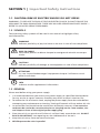
SECTION 1
Important Safety Instructions ................................................ 3
SECTION 2
Layout & Dimensions ........................................................... 5
SECTION 3
Description & Overview ........................................................ 7
SECTION 4
Installation ........................................................................... 9
SECTION 5
Operation ........................................................................ 13
SECTION 6
Limiting Electro-Magnetic Interference (EMI) ...................... 15
SECTION 7
Troubleshooting Guide ...................................................... 18
SECTION 8
Specications .................................................................... 19
SECTION 9
Warranty ....................................................................... 21
OWNER'S MANUAL | Index
Disclaimer of Liability
UNLESS SPECIFICALLY AGREED TO IN WRITING, SAMLEX AMERICA INC.:
1. MAKES NO WARRANTY AS TO THE ACCURACY, SUFFICIENCY OR SUITABILITY OF ANY TECHNICAL OR OTHER INFORMATION
PROVIDED IN ITS MANUALS OR OTHER DOCUMENTATION.
2. ASSUMES NO RESPONSIBILITY OR LIABILITY FOR LOSSES, DAMAGES, COSTS OR EXPENSES, WHETHER SPECIAL, DIRECT,
INDIRECT, CONSEQUENTIAL OR INCIDENTAL, WHICH MIGHT ARISE OUT OF THE USE OF SUCH INFORMATION. THE USE OF
ANY SUCH INFORMATION WILL BE ENTIRELY AT THE USERS RISK.
Samlex America reserves the right to revise this document and to periodically make changes to the content
hereof without obligation or organization of such revisions or changes.
Copyright Notice/Notice of Copyright
Copyright © 2018 by Samlex America Inc. All rights reserved. Permission to copy, distribute and/or modify this
document is prohibited without express written permission by Samlex America Inc.

2 | SAMLEX AMERICA INC. SAMLEX AMERICA INC. | 3
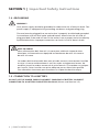
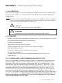
1.1 CAUTION: RISK OF ELECTRIC SHOCK! DO NOT OPEN!
WARNING—TO REDUCE THE RISK OF FIRE OR ELECTRIC SHOCK, DO NOT EXPOSE THIS
APPLIANCE TO RAIN OR MOISTURE. THERE ARE NO USER SERVICEABLE PARTS INSIDE —
REFER TO QUALIFIED SERVICE PERSONNEL.
1.2 SYMBOLS
The following safety symbols will be used in this manual to highlight safety
and information:
WARNING!
Indicates possibility of physical harm to the user in case of non-compliance.
MISE EN GARDE!
L’utilisateur pourrait se blesser lorsque les consignes de sécurité ne sont pas
suivies.
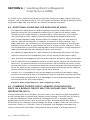
!
CAUTION!
Indicates possibility of damage to the equipment in case of non-compliance.
!
ATTENTION!
Il y a un risque d’endommager l’équipement lorsque l’utilisateur ne suit
pasles instructions.
i
INFO
Indicates useful supplemental information.
1.3 GENERAL
Please read before using your power supply:
1. It Is recommended that you return your power supply to a qualied Samlex dealer
for any service or repair. Incorrect assembly may result in electric shock or re.
2. To reduce the risk of electric shock, unplug the power supply from the outlet before
attempting any maintenance or cleaning. Turning off controls will not reduce this risk.
3. An extension cord should not be used unless absolutely necessary. If an extension
cord must be used make sure that the pins on the plug are the same number, size
and shape as those of the original power supply plug.
4. Place the unit in an area that will allow air to ow freely around the unit. DO NOT
BLOCK OR OBSTRUCT vent openings on the side/bottom of the unit.
5. Keep the unit away from moisture and water.
6. NEVER operate the units in parallel.
SECTION 1 | Important Safety Instructions

4 | SAMLEX AMERICA INC.
1.4 GROUNDING
WARNING!
Your power supply should be grounded to reduce the risk of electric shock. The
power supply is equipped with grounding conductor and grounding plug.
The cord must be plugged into an outlet that is properly installed and grounded
in accordance with all local codes and ordinances. Never alter the AC cord of
plug provided. If the cord will not t the outlet, have a proper outlet installed by
qualied electrician. Improper connection can result in risk of electric shock.
MISE EN GARDE!
Votre alimentation doit être mis à la terre pour réduire le risque de choc
électrique. L’alimentation est équipé d’un conducteur de mise à la terre et
de mise à la terre.
Le cordon doit être branché dans une prise de courant correctement installée
et mise à la terre conformément à tous les codes et règlements locaux. Ne
modiez jamais le cordon secteur de la prise fournie. Si le cordon ne s’adapte
pas la prise, faites installer une prise adéquate par un électricien qualié.
Une connexion incorrecte peut entraîner un risque de choc électrique.
1.5 CONNECTION TO A BATTERY
DO NOT USE THE POWER SUPPLY FOR DIRECT CHARGING OF BATTERY OR DIRECT
CONNECTION TO A BATTERY FOR BATTERY BACK-UP. (Please read Section 3.5).
SECTION 1 | Important Safety Instructions

4 | SAMLEX AMERICA INC. SAMLEX AMERICA INC. | 5
SECTION 2 | Layout & Dimensions
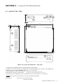
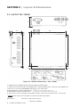
2.1 LAYOUT SEC-1235
61
53.3
185
13.5
4.5190
208
190
7.7
2.5 2.5
180
Figure 2.1 Layout & Dimensions - SEC-1235
1. Lighted Power ON/OFF Rocker Switch (Lights Red when ON)
2. AC Power Cord Inlet: Type “IEC 60320-C14” for detachable power cord with “IEC 60320-C13”
connector on one end and NEMA5-15P plug on the other end.
3. Black Negative (-) DC Load Terminal
4. Red Positive (+) DC Load Terminal
5. Ventilation slots (Additional row of ventilation slots in the bottom - not shown)
* NOTE: 5/64” Hex key and 2 spare set screws have been provided
Dimensions: W x D x H 185 x 208 x 61 mm
7.28 x 8.19 x 2.40 i
n
{Tubular hole Dia 5mm/0.2” and set screw
(5/64” Hex Socket Head, #10, 24 TPI, 5/16” long)}*

6 | SAMLEX AMERICA INC.
SECTION 2 | Layout & Dimensions
2.2 LAYOUT SEC-1235M
61
53.3
185
13.5
8.5190
208
190
7.7
2.5 2.5
180
Figure 2.2 Layout & Dimensions - SEC-1235M
1. Lighted Power ON/OFF Rocker Switch (Lights Red when ON)
2. AC Power Cord Inlet: Type “IEC 60320-C14” for detachable power cord with “IEC 60320-C13”
connector on one end and NEMA5-15P plug on the other end.
3. Black Negative (-) DC Load Terminal
4. Red Positive (+) DC Load Terminal
5. Air inlet slots for cooling fan (cooling fan and air outlet slots at the bottom - not shown)
* NOTE: 5/64” Hex key and 2 spare set screws have been provided
Dimensions: W x D x H 185 x 212 x 61 mm
7.28 x 8.35 x 2.40 i
n
{Tubular hole Dia 5mm/0.2” and set screw
(5/64” Hex Socket Head, #10, 24 TPI, 5/16” long)}*

6 | SAMLEX AMERICA INC. SAMLEX AMERICA INC. | 7
SECTION 3 | Description & Overview
3.1 DESCRIPTION
SEC-1235 / SEC-1235M are switched mode power supplies which convert 120 VAC, 50/60
Hz (or 230 VAC, 50/60 Hz*) to regulated 13.8 VDC based on pulse width modulation
(PWM) control.
*NOTE: The units are factory preset to operate from input voltage of 120 VAC, 50/60 Hz.
These may be set to operate from input voltage of 230 VAC, 50/60 Hz by chang-
ing internal setting described at Section 4.5.2.
!
CAUTION!
UL listing is not valid for 230 VAC input option.
!
ATTENTION!
Inscription UL n’est pas valide pour l’option d’entrée 230 VAC.
3.2 FEATURES
- Based on switched mode technology and PWM control. Switching frequency: 30.5 KHz
- SEC-1225M comes with Voltmeter and Ammeter
- Compact and lightweight.
- High efciency and less heat dissipation.
- Protected against short circuit, over current and over voltage
(through PWM controller).
- Forced air cooling and over temperature shut down.
- UL listed and approved.
- Complies with FCC part 15(B) for radiated & conducted noises for Class-B
digital devices.
3.3 COOLING AND OVER TEMPERATURE PROTECTION
The units are cooled by convection and by forced air. A temperature controlled fan has
been provided to improve cooling at higher loads. The fan is controlled by a sensor
mounted on the power transformer. THE FAN WILL BE OFF AT LOWER LOADS. It will
come on only when the temperature of the power transformer is ≥ 60ºC ± 5ºC / 140ºF
± 9ºF due to higher loads or higher ambient temperature or poor cool air circulation
around the unit. The fan will switch off automatically at ≤ 40ºC ± 5ºC / 104ºF ± 9ºF. In
case the fan fails or the air ow is blocked, a second temperature sensor mounted on
the power transformer will activate over temperature shut down at ≥ 105ºC ± 5ºC /
221ºF ± 9ºF. The output voltage will be automatically resumed once the unit cools down
to ≤ 75ºC ± 5ºC / 167ºF ± 9ºF. PLACE THE UNITS IN A WELL VENTILATED OPEN AND COOL
AREA. DO NOT BLOCK THE OPENINGS AT THE FAN DISCHARGE ON THE BOTTOM AND
THE SUCTION OPENINGS ON THE SIDES.

8 | SAMLEX AMERICA INC.
SECTION 3 | Description & Overview
3.4 BATTERY CHARGING & BATTERY BACK-UP
WARNING!
These units are power supplies and not battery chargers. Do not connect these
units directly to a battery.
MISE EN GARDE!
Ces unités sont des unités d’alimentation et non pas les chargeurs de batterie.
Ne pas connecter ces appareils directement à une batterie.
These units should NOT BE DIRECTLY CONNECTED TO A BATTERY for charging or for
battery back-up. Battery charging and battery back-up may be undertaken only when the
battery is connected through suitable external isolating diodes and charge limiting resistor.
The isolating diode will ensure that the battery does not back power the power supply.
When a battery is deeply discharged, it will initially draw a very large charging current
and thus, will force the power supply into current limit mode for prolonged periods.
This is harmful for the power supply. The charge limiting resistor will limit the charging
current, thereby, ensuring that the maximum charging current is well below the current
limit value of the power supply.
i
INFO
It is recommended that optional battery back-up module BBM-12100 may be
used to convert SEC-1235 / SEC-1235M for battery back-up application.

8 | SAMLEX AMERICA INC. SAMLEX AMERICA INC. | 9
4.1
WARNING!
1. Before commencing installation, please read the safety instructions
explained in Section 1 titled “Important Safety Instructions”.
2. It is recommended that the installation should be undertaken by a
qualied, licensed / certied electrician.
3. Various recommendations made in this manual on installation will be
superseded by the National / Local Electrical Codes related to the loca-
tion of the unit and the specic application.
MISE EN GARDE!
1. Avant de commencer l’installation, veuillez lire les instructions de sécurité
a expliqué à la section 1 intitulée “Instructions de sécurité importantes”.
2. Il est recommandé que l’installation doit être effectuée par un tech-
nicien qualié, autorisé / électricien certié.
3. Différentes recommandations faites dans ce manuel sur l’installation
sera remplacée par la National / les codes électriques locaux liés à
l’emplacement de l’unité et l’application spécique.
4.2 INSTALLATION DIMENSIONS
Refer to Section 2, Figs 2.1 for installation dimensions for SEC-1235 and Section 2, Fig 2.2
for installation dimensions for SEC-1235M.
4.3 LOCATION OF INSTALLATION
Please ensure that the following requirements are met:
Working Environment: Indoor use.
Cool: Heat is the worst enemy of electronic equipment. Hence, please ensure that the
units are installed in a cool area that is also protected against heating effects of direct
exposure to the sun or to the heat generated by other adjacent heat generating devices.
Well ventilated: The units are cooled by convection and by forced air-cooling by tem-
perature controlled fan on the bottom of the unit. The fan at the bottom draws cool
air from air intake openings on the sides and discharges hot air through the exhaust
openings under the fan. To avoid shut down of the units due to over temperature, do
not cover or block the ventilation / suction / exhaust openings or install the units in an
area with limited airow. Keep a minimum clearance of 10” around the units to provide
adequate ventilation. If installed in an enclosure, openings must be provided in the
enclosure, directly opposite to the air-suction and air-exhaust openings of the unit.
Dry: There should be no risk of condensation, water or any other liquid that can enter
or fall on the units.
SECTION 4 | Installation

10 | SAMLEX AMERICA INC.
Clean: The area should be free of dust and fumes. Ensure that there are no insects or
rodents. They may enter the units and block the ventilation openings or short circuit
electrical circuits inside the units.
Protection against re hazard: The units are not ignition protected and should not be
located under any circumstance in an area that contains highly ammable liquids like
gasoline or propane as in an engine compartment with gasoline-fueled engines. Do not
keep any ammable / combustible material (i.e., paper, cloth, plastic, etc.) near the units
that may be ignited by heat, sparks or ames.
Accessibility: Do not block access to the front panel. Also, allow enough room to access
the AC inlet and the DC wiring terminals and connections at the back of the unit, as
they will need to be checked and tightened periodically.
Preventing Radio Frequency Interference (RFI): The units use high power switching cir-
cuits that generate RFI. This RFI is limited to the required standard – FCC Part 15(B), Class
B. Locate any electronic equipment susceptible to radio frequency and electromagnetic
interference as far away from the unit as possible. For additional information, please
read Section 6 titled “Limiting Electromagnetic Interference (EMI)”.
4.4 MOUNTING ORIENTATION
The units have air intake openings on the sides and exhaust openings at the bottom for
the cooling fan. The units should be mounted in such a manner so that small objects
should not be able to fall easily into the units from these openings and cause electrical /
mechanical damage. Also, the mounting orientation should be such that if the internal
components overheat and melt / dislodge due to a catastrophic failure, the melted /
hot dislodged portions should not be able to fall out of the unit on to a combustible
material and cause a re hazard. The size of openings has been limited as per the
safety requirements to prevent the above possibilities when the unit is mounted in the
recommended orientations. In order to meet the regulatory safety requirements, the
mounting has to satisfy the following requirements:
- Mount on a non-combustible material.
- The mounting surface should be able to support the weight of the unit
- Mount horizontally on a horizontal surface (e.g. table top or a shelf)
- Mounting horizontally on a vertical surface – The unit can be mounted on a vertical
surface (like a wall) with the DC output terminals either facing up or down
WARNING!
Mounting the unit on a vertical surface with the ventilation slots on the sides
facing up / down is NOT recommended. As explained above, this is to prevent
(i) falling of objects into the unit through the slots causing short circuit or (ii)
falling out of dislodged overheated / melted components on to a combustible
material in case of catastrophic internal failure.
SECTION 4 | Installation

10 | SAMLEX AMERICA INC. SAMLEX AMERICA INC. | 11
MISE EN GARDE!
Montage de l’appareil sur une surface verticale avec les fentes de ventilation sur les
côtés vers le haut / vers le bas n’est pas recommandé. Comme expliqué ci-dessus, il
s’agit d’éviter que (i) la chute d’objets dans l’unité à travers les fentes provoquant
un court-circuit ou (ii) en tombant de délogé / composants surchauffés fondu sur un
matériau combustible en cas de défaillance interne catastrophique.
4.5 AC SIDE CONNECTION
4.5.1 Connection for nominal AC input voltage of 120VAC (range: 100-130VAC),
50/60Hz (Factory preset condition)
The unit has been factory preset for nominal AC input voltage of 120VAC (range:100-
130VC), 50/60Hz.
120VAC power is fed to the unit through detachable, 120 VAC power cord supplied with
the unit. The power cord has the following specications:
• Length of the cord: 6 ft
• Cable : 3 conductors (Line – black; Neutral – White; Grounding - Green), each
AWG #16
• 13A, 125V female connector “IEC 60320-C13” for power supply end.
Insert this end into the AC Power Inlet on the unit (2, Figs 2.1 / 2.2)
• 13A, 125V “NEMA5-15” plug for connecting to 120 VAC outlet
4.5.2 Connection for nominal AC input voltage of 230VAC (range: 200-260VAC),
50/60Hz (will require internal jumper setting)
The unit can also be operated from nominal AC input voltage of 230VAC (range: 200 to
260VAC), 50/60Hz by internal jumper setting, changing internal fuse size and changing
AC power cord as described below:
4.5.2.1 Changing internal jumper setting
a) Switch off the unit and unplug the AC power cord from the AC outlet supplying
AC power to the unit.
b) Remove the top cover by unscrewing 4 screws
c) For 120VAC operation (factory preset condition), points marked “C” and “E” on
the Printed Circuit Board (PCB) have been connected (shorted) with a exible,
yellow colored jumper wire that has black colored Quick Disconnect Terminal
at the 2 ends. To convert to 230VAC operation, disconnect the Quick Connect
Terminal of the jumper wire at point “C” by pulling it upwards. Insulate this end
with insulation tape and use a cable tie to tie it securely to the nearby wire bundle.
4.5.2.2 Changing internal Fuse
a) For the factory preset 120 VAC operation, the internal AC input side Fuse is
rated at 250VAC, 8A. For 230VAC operation, remove this Fuse and replace with a
similar 250VAC, 4A Fuse (Littelfuse Part No. 0218004 or equivalent)
SECTION 4 | Installation

12 | SAMLEX AMERICA INC.
4.5.2.3 Changing detachable AC Power Cord
a) Change the supplied detachable AC power cord with detachable power cord that
has “IEC 60320 – C13” female connector for the power supply end and a plug on
the other end with 3 pin conguration to suit the 230V country specic outlet.
4.6 DC OUTPUT CONNECTIONS
4.6.1 DC Output Terminals
DC output is provided as follows:
• Red Positive Terminal (4, Figs 2.1 and 2.2):
o Tubular Hole – Diameter 5 mm / 0.2”
o *Set Screw: 5/64” Hex Socket Head Screw; #10, 24 TPI, 5/16” long
• Black Negative Terminal (3, Figs 2.1 and 2.2):
o Tubular Hole – Diameter 5 mm / 0.2”
o *Set Screw: 5/64” Hex Socket Head screw; #10, 24 TPI, 5/16” long*
*NOTE: The following have been provided for convenience:
a) 5/64” Hex / Allen Key for the Hex Socket Head Screw.
RETAIN THE HEX / ALLEN KEY FOR FUTURE USE
b) 2 spare Hex socket head screws
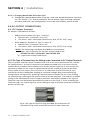
4.6.2 Pin Type of Terminal Lugs for Wiring to be Connected to DC Output Terminals
The DC output terminals have a tubular hole with a set screw (See Section 4.6.1 above
for specications). As the DC terminals have been provided with a set screw, do not
connect bare stranded wire end directly to the DC output terminal as the strands will
spread out when the set screw is tightened and all the strands may not be pinched
rmly under the set screw. This will result in (i) reduction in effective area of cross
section for current conduction leading to increased voltage drop and overheating
along output wiring and (ii) Sparking / loose connection under the set screw leading
to overheating / melting of the plastic material of the terminals. The ends of stranded
wiring to be connected to the DC output terminals should be crimped to Pin Type of
Terminal Lugs that have been provided with the unit (see Fig 4.1). After crimping the
Terminal Lugs, use insulating heat shrink tubing or tape to insulate the bare cylindrical
portion of the lugs.
Fig 4.1 Pin type of terminal lugs provided for termination of
stranded wiring to be connected to the DC input terminals.
SECTION 4 | Installation

12 | SAMLEX AMERICA INC. SAMLEX AMERICA INC. | 13
5.1
WARNING!
1. Before commencing operation, please read the safety instructions
explained in Section 1 titled “Important Safety Instructions”.
2. Ensure that the unit has been installed as per guidelines given in Section 4
titled “Installation”.
3. The unit has been factory preset for operation from nominal AC input
voltage of 120VAC, 50/60Hz. It the unit is to be operated from nominal AC
voltage of 230 VAC, 50/60 Hz, please change internal input jumper setting,
internal fuse and AC power cord as per instruction given at Section 4 titled
“Installation”.
NOTE: If the unit is operated from 230VAC without making the above
changes, the input section of the unit will be damaged and
warranty will be voided.
MISE EN GARDE!
1. Avant de commencer, veuillez lire les instructions de sécurité a expliqué à la
section 1 intitulée “Instructions de sécurité importantes”.
2. S’assurer que l’unité a été installée selon les directives données dans la sec-
tion 4 intitulée “Installation”
3. The unit has been factory preset for operation from nominal AC input voltage
of 120VAC, 50/60Hz. It the unit is to be operated from nominal AC voltage of
230 VAC, 50/60 Hz, please change internal input jumper setting, internal fuse
and AC power cord as per instruction given at Section 4 titled “Installation”.
NOTE: Si l’appareil est utilisé à partir de 230 VCA sans faire les
changements ci-dessus, la section d’entrée de l’appareil sera
endommagé et et la garantie sera annulée.
5.2 SWITCHING ON PROCEDURE
a) Plug the supplied AC Power Cord to the AC Power Cord Inlet on the unit
(2, Fig 2.1 / 2.2)
b) Ensure that the power supply’s On/Off Switch (1, Fig 2.1 / 2.2) is in off
position (edge of the switch with marking “o” will be in pressed down
condition).
c) Switch off the 12V DC load that is required to be powered from the power supply.
d) Ensure that the ends of the Positive and Negative wires of the DC load to
be connected to the power supply have been properly terminated with Pin
Type Terminal Lugs as explained at Section 4.6.2.
e) Connect the Positive wire from the DC load to the Red Positive DC Input
Terminal (4, Fig 2.1 / 2.2) of the power supply and the Negative wire from
the DC load to the Black Negative DC Input Terminal (3, Fig 2.1 / 2.2) of the
power supply. Use 5/64” Hex Key provided with the unit to tighten the Hex
Socket Head set screws to ensure that the connections are secure and tight
f) Plug the AC Power Cord to the AC outlet. Ensure that AC power is available
in the outlet.
SECTION 5 | Operation

14 | SAMLEX AMERICA INC.
g) Switch on the unit by pressing down on the edge of the switch marked
“ – ”. Neon light inside the switch will be lighted
h) 13.8 VDC will now be available at the DC output terminals (4, 3 in Fig 2.1 / 2.2)
i) Now switch on the DC load
5.3 SWITCHING OFF PROCEDURE
a) Switch off the DC load rst
b) Switch off the power supply by pressing down on the edge of the switch
marked “o”
c) Unplug the AC power cord from the AC outlet
5.4 TROUBLESHOOTING
Refer to the Troubleshooting Guide at Section 7 in case of any abnormal operation.
SECTION 6 | Limiting Electro-Magnetic
Interference (EMI)
6.1
!
CAUTION!
Conducted and radiated noises in this unit are limited as per the applicable
National / International Standards as detailed under Compliance: EMI in
Section 8.
This unit generates, uses and can radiate radio frequency energy and, if not
installed and used in accordance with the instructions, may cause harmful
interference to radio communications. However, this does not guarantee that
interference will not occur in a particular installation. If this equipment does
cause harmful interference to radio or television reception, which can be
determined by turning the equipment off and on, the user is encouraged to
try to correct the interference by one or more of the measures recommended
in the following paragraphs.
!
ATTENTION!
Bruits et rayonnement dans cette unité sont limitées que par la législation
nationale / normes internationales comme détaillé dans le cadre de
conformité : EMI dans la section 8.
Cet appareil génère, utilise et peut émettre une énergie de fréquence
radio et, s’il n’est pas installé et utilisé conformément aux instructions, peut
causer des interférences nuisibles aux communications radio. Cependant,
SECTION 5 | Operation

14 | SAMLEX AMERICA INC. SAMLEX AMERICA INC. | 15
cela ne garantit pas qu’aucune interférence ne se produira dans une
installation particulière. Si cet équipement provoque des interférences
nuisibles à la réception radio ou télévision, ce qui peut être déterminé en
éteignant l’équipement, l’utilisateur est encouragé à essayer de corriger les
interférences en prenant une ou plusieurs des mesures recommandées dans
les paragraphes suivants.
6.2 UN-INTENTIONAL RF NOISE GENERATED BY SWITCHED MODE
POWER SUPPLIES (SMPS)
Switched Mode Power Supplies (SMPS) employ high frequency switching (30.5 KHz in
these units) and thus, are a source of radio interference, a recipient of radio interference
and a conduit of radio interference. (Older Linear Type, low frequency 50 / 60 Hz
transformer based power supplies do not employ high frequency switching voltages and
will be quieter as compared to SMPS).
The emission sources originate in the switching devices due to their fast switching
current transitions: harmonics of the switching frequency and broadband noise created
by under-damped oscillations in the switching circuit. The noise is both conducted and
radiated through the input power cord and the DC output wiring to the radio.
6.3 FILTRATION OF CONDUCTED NOISE
The conducted RF noise from this SMPS unit is limited to the maximum allowable levels by
internal ltration. The ltered RF noise currents (< few hundred micro Amps) are bypassed
to the chassis of the power supply. The chassis is, in turn, connected to the Earth Ground
pin of the AC input power cord (for Class 1 units). Thus, the ltered noise currents are
intentionally leaked to the Earth Ground. This is termed as the “Earth Leakage Current”.
6.4 EXCESSIVE RF OUTPUT INTERFERENCE BY SMPS DUE TO
INCOMING RF INTERFERENCE WHEN POWERING RADIO TX / RX
SMPS are also recipients of radio interference. The normal operation of the power
supply can be disturbed due to RF noise getting coupled into the power supply. Thus,
the power supply may generate excessive RF noise and lose output voltage regulation
due to excessive transmitter energy being coupled through the AC / DC lines to the
power supply’s regulator feedback path. This may be due to antenna being too close
or due to the antenna or feed system not radiating properly. First, check the antenna
system SWR. Then, if necessary, relocate either the antenna or the power supply farther
apart. The receiver may “hear” the power supply. A slowly moving, slightly buzzing
carrier heard in the receiver may be caused by the antenna being too close. As with the
transmitter related noise pick up, a loose coaxial connector or a broken or a missing
ground may aggravate this problem. Normally, this noise will be below the background
SECTION 6 | Limiting Electro-Magnetic
Interference (EMI)

16 | SAMLEX AMERICA INC.
or “band” noise. Increase the separation between the power supply and the receiving
antenna. Use an outdoor antenna. This will reduce the amount of signal picked up from
the power supply and also increase the amount of the desired signal.
6.5 ADDITIONAL GUIDELINES FOR REDUCING RF NOISE
• Use additional appropriate AC Radio Frequency Interference (RFI) Power Line Filter
rated for minimum 10A immediately before the AC input of the power supply.
Filtered, Ferrite Coated Cord Set is another choice. These cord sets, with integral
line interference lters, reduce Common and Differential Mode Interferences
over a wide frequency range. Because they are shielded, they are also effective
against radiated interferences. In addition to the built-in lter networks, the
cable conductors are coated with an RF absorbing ferrite compound. This provides
additional attenuation at high frequencies that is lacking in most regular LC lters.
The RF absorption of the ferrite-coated cable avoids resonances at high frequencies,
reducing the conducted and radiated RF noises even further.
• Use additional appropriate DC radio frequency interference (RFI) power line lter
rated for minimum 35A immediately after the DC output of the power supply.
• Twist the Positive and Negative wires from the output of the power supply to the radio.
• The DC side Positive and Negative outputs of these power supplies are isolated from
the chassis. As explained earlier, the noise currents are ltered to the chassis of the
unit and the chassis is connected to the Earth Ground through the Earth Ground Pin
of the AC power outlet receptacle. Avoid connecting (referencing) the DC Negative
output terminal of the power supply to the Earth Ground.
• Connect a ¼” wavelength of wire on the Negative terminal of the power supply.
Connect one end of the wire to the Negative terminal and leave the other end free.
The wavelength corresponds to the wavelength of the interfering frequency. (May
not be practical for long wave lengths).
[Formula: Wave length (Meters) = 300 / frequency in MHz]
6.6 COMBINED FILTERED NOISE CURRENTS FROM MULTIPLE
SMPS ON A BRANCH CIRCUIT MAY TRIP GROUND FAULT CIRUIT
INTERRUPTER (GFCI)
During malfunction or an accident, the metal chassis of a device may get energized to
unsafe voltage due to internal high voltage section coming in contact with the chassis.
If a person standing on Earth touches this energized chassis, a leakage current
proportional to the person’s skin resistance will ow through the person’s body to
Earth Ground. The leakage current through the body is higher when the skin contact
resistance is lower i.e. if the skin is wet or wounded. This leakage current does not
return to the power source but is dissipated in Earth Ground. A leakage current of
SECTION 6 | Limiting Electro-Magnetic
Interference (EMI)

16 | SAMLEX AMERICA INC. SAMLEX AMERICA INC. | 17
> 4 to 6mA could produce lethal electrical shock. Ground Fault Circuit Interrupter (GFCI)
is used for safety against electrical shock due to leakage. GFCI measures the difference
between the current sent to the load and returned from the load and will trip and
disconnect the power circuit if the difference is > 4 to 6mA. GFCIs are normally installed
in AC Branch Circuits feeding power outlets in wet areas like marine craft, RVs, spas,
hot-tubs, kitchens, washrooms, etc.
As explained earlier, RF noise ltration circuits in SMPS generate intentional Earth
Leakage Current. SMPS are used extensively as DC power sources in modern day
electrical / electronic devices e.g. Audio / Video / Computing devices, power supplies,
battery chargers etc. A single GFCI outlet / GFCI breaker may be serving multiple SMPS
loads and therefore, will be sensing the sum of all the Earth Leakage Currents and, if the
sum is > 4 to 6mA after connecting this unit, the GFCI will trip. In such a case, disconnect
other SMPS based device(s) being served by this GFCI one by one till the net leakage
current is reduced to < 4mA and the GFCI does not trip. Other solution is to power this
unit from a GFCI outlet / GFCI breaker that does not have any SMPS load or power from
an outlet that is not protected by GFCI.
SECTION 6 | Limiting Electro-Magnetic
Interference (EMI)

18 | SAMLEX AMERICA INC.
SECTION 7 | Troubleshooting Guide
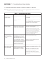
7.1 TROUBLESHOOTING GUIDE IS GIVEN AT TABLE 7.1 BELOW
NOTE: This guide is based on operation as a power supply (only DC load is connected -
no external battery or battery backup).
TABLE 7.1 TROUBLESHOOTING GUIDE
Symptom Possible Cause Remedy
ON / OFF Switch is ON
• Switch is NOT lighted
• No DC output
No AC power from the
AC outlet
Internal AC side fuse
is blown
Check AC power is available at the AC
outlet. Breaker feeding the AC outlet may
have tripped.
Open the top cover and check the AC side
fuse. Replace if blown.
If the fuse blows again, the input section is
damaged. Please call Tech Support.
ON / OFF Switch is ON
• Switch is lighted
• No DC output
Unit has shut down due to over
temperature – Temperature of
output transformer windings is:
≥ 105°C ± 5°C / 221°F ± 9°F
Check that the fan is running. If not, the
fan / fan control circuit may have been
damaged. Call Tech Support.
Check that the fan suction vents on the
sides of the unit and the discharge vents on
the bottom of the unit are not blocked.
The unit will reset automatically when the
transformer windings cool down to
≤ 75°C ± 5°C / 167°F ± 9°F
ON / OFF Switch is ON
• Switch is lighted
• DC Output voltage
drops
If the voltage loses regulation
and drops to < 13.5V, the unit
is overloaded and is in current
limit. The load is trying to draw ≥
the current limit value
If the voltage drop is consider-
able with voltage < 2V, the load
side is seeing a short circuit and
short circuit current limited to
the current limit value is being
driven into the short circuit
Reduce the current drawn by the load to
less than the continuous rating.
Switch OFF the load. Remove the short
circuit on the load side.
GFCI outlet / GFCI break-
er supplying AC power
to the unit trips when the
unit is switched ON
Additional RF noise currents from
the unit that are ltered to Earth
Ground increase the net Leakage
Current on the GFCI outlet /
GFCI breaker to > 4 to 6mA
Switch OFF other SMPS devices operating
from the same GFCI outlet / GFCI breaker
to reduce the net leakage current to < 4mA
Move the unit to another GFCI outlet /
GFCI breaker that has lesser number of
SMPS load(s) or no SMPS load
Power the unit from normal, non GFCI
outlet or from an outlet not protected by
GFCI breaker

18 | SAMLEX AMERICA INC. SAMLEX AMERICA INC. | 19
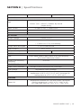
SECTION 8 | Specications
SEC-1235 SEC-1235M
AC INPUT
Nominal AC Input Volt-
age
120 VAC (100-130VAC), 50/60 Hz : Factory Preset
230VAC (200 – 260VAC), 50/60Hz: By internal
jumper setting
Input Current 7.5 A @ 120 VAC; 3.5A @ 230VAC
Input Current at No Load 120 mA ± 10% @120VAC
Inrush current at Startup 30A +/- 5A for < 5 ms
DC OUTPUT
Output Voltage 13.8VDC ± 0.1V
Output Current • Continuous: 30A;
• Current Limit: 35A, Auto recovery
Output Noise and Ripple < 150 mV Peak to Peak
Peak Efciency 85% +/-5%
Output Metering - Voltmeter and Ammeter
DESIGN
Type Switch Mode Power Supply (SMPS) with Fixed Frequency
Pulse Width Modulation (PWM)
Output Side Switching
Frequency
30.5 KHz
PROTECTIONS
Short Circuit, Overload Constant Current Limiting at 35A; Auto Reset
Over Voltage Regulated by PWM Controller
Over Temperature Output shuts down when Power Transformer winding
temperature ≥ 105°C ± 5°C / 221°F ± 9°F; Auto reset on
cooling down to ≤ 75°C ± 5°C / 167°F ± 9°F
COOLING
Forced Air
Temperature controlled fan. ON when Power Transformer
winding temperature is ≥ 60°C ± 5°C / 140°F ± 9°F;
OFF when cools down to ≤ 40°C ± 5°C / 104°F ± 9°F

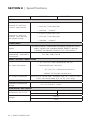
20 | SAMLEX AMERICA INC.
SECTION 8 | Specications
SEC-1235 SEC-1235M
FUSE
Internal AC Side Fuse,
120VAC Input (Preset)
• 5 mm x 20 mm Glass Fuse
• 250V, 8A, Time Delay Type
• Littelfuse - “218008”
Internal AC Side Fuse,
230VAC Input (By inter-
nal jumper setting)
• 5 mm x 20 mm Glass Fuse
• 250V, 4A, Time Delay Type
• Littelfuse - “218004”
COMPLIANCE
Safety
UL safety listed as “Information Technology Equipment Power
Supply” for USA (UL Standard ANSI/UL-60950-1) and for
Canada (CSA Standard CAN/CSA-C22.2 No. 60950-1)
Electro Magnetic Inter-
ference EMI – Radiated &
Conducted
FCC Part 15(B), Class B
INPUT / OUTPUT CONNECTIONS
AC Input Connection
• “IEC 320-C14” Inlet Connector on the unit
• Detachable Power Cord with:
“IEC 320-C13” Connector on one end
NEMA5-15P Plug on the other end
DC Output Connectors Terminal with Tubular Hole - Diameter 5mm / 0.2” and set screw
(5/64” Hex Socket Head, #10, 24 TPI, 5/16” long)
ENVIRONMENTAL
Operating Temperature
Range
0°C / 32°F to 40°C / 104°F
DIMENSIONS AND WEIGHT
Dimensions (W x D x H)
185 x 208 x 61 mm 185 x 212 x 61 mm
7.28 x 8.19 x 2.40 in 7.28 x 8.35 x 2.40 in
Weight
1.54 kg
3.4 lb
La page est en cours de chargement...
La page est en cours de chargement...
La page est en cours de chargement...
La page est en cours de chargement...
-
 1
1
-
 2
2
-
 3
3
-
 4
4
-
 5
5
-
 6
6
-
 7
7
-
 8
8
-
 9
9
-
 10
10
-
 11
11
-
 12
12
-
 13
13
-
 14
14
-
 15
15
-
 16
16
-
 17
17
-
 18
18
-
 19
19
-
 20
20
-
 21
21
-
 22
22
-
 23
23
-
 24
24


Samlexpower SEC-1235M Le manuel du propriétaire
- Taper
- Le manuel du propriétaire
- Ce manuel convient également à
dans d''autres langues
- English: Samlexpower SEC-1235M Owner's manual
Documents connexes
-
Samlexpower SEC-1223 Le manuel du propriétaire
-
Samlexpower SEC-1223BBM Le manuel du propriétaire
-
-
-
-
-
-
-
