
Gas and Electric Clothes Dryers
Sécheuses électriques et à gaz
Secadoras de ropa a gas y eléctricas
User Manual
Manuel d’utilisation
Manual para el usuario
GDE560BW/GDG560BW/CGDE560BW


1
TABLE OF CONTENTS
IMPORTANT SAFETY INSTRUCTIONS .................................................................2
Gas Dryer Precautions .................................................................................................. 3
Installation Safety Precautions ..................................................................................... 3
General Safety Precautions .......................................................................................... 4
PARTS AND FEATURES .......................................................................................5
INSTALLATION INSTRUCTIONS .......................................................................... 6
Tools Needed ................................................................................................................. 6
Additional Parts Required .............................................................................................. 6
Location Requirements ................................................................................................. 7
Electrical & Gas Supply Requirements .......................................................................... 8
Gas Supply Connection Requirements .......................................................................11
Burner Input Requirements .........................................................................................11
Exhaust System Requirements ...................................................................................12
Mobile Home - Additional Requirements ..................................................................14
STEP BY STEP INSTRUCTIONS .......................................................................... 15
Step 1 - Unpack the Dryer ...........................................................................................15
Step 2 - Attach a Power Cord to the Dryer (Electric Dryer Only) ..............................15
Step 2 - Connect to a Gas Supply Line (Gas Dryer Only) ...........................................18
Step 3 - Connect to an Exhaust System .....................................................................19
Step 4 - Level the Dryer ..............................................................................................20
Step 5 - Complete the Installation ..............................................................................20
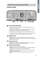
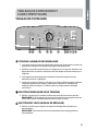
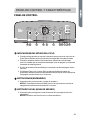
CONTROL PANEL AND FEATURES .................................................................... 21
OPERATING INSTRUCTIONS ............................................................................. 25
Step 1 - Prepare and Sort Laundry .............................................................................25
Step 2 - Clean the Lint Screen ....................................................................................25
Step 3 - Load the Dryer ...............................................................................................26
Step 4 - Start the Dryer ...............................................................................................26
CARE AND CLEANING GUIDE ............................................................................ 27
Cleaning and Maintenance ..........................................................................................27
Washing the Lint Screen ..............................................................................................27
Removing Accumulated Lint .......................................................................................27
Replace Interior Drum Light Bulb ................................................................................28
Vacationing Precautions .............................................................................................28
Moving or Storage Preparation ...................................................................................28
TROUBLESHOOTING ........................................................................................ 29
LIMITED WARRANTY ........................................................................................ 31
RECORD KEEPING
Thank you for purchasing this Haier
product. This user manual will help you
get the best performance from your
new dryer.
For future reference, record the model
and serial number located on back of
the dryer, and the date of purchase.
Staple your proof of purchase to this
manual to aid in obtaining warranty
service if needed.
___________________________________
Model number
___________________________________
Serial number
___________________________________
Date of purchase

2
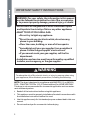
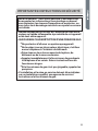
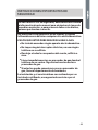
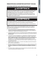
IMPORTANT SAFETY INSTRUCTIONS
-Do not store or use gasoline or other flammable vapors
and liquids in the vicinity of this or any other appliance.
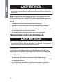
-WHAT TO DO IF YOU SMELL GAS:
●
Do not try to light any appliance.
●
Do not touch any electrical switch; do not use any
phone in your building.
●
Clear the room, building, or area of all occupants.
●
Immediately call your gas supplier from a neighbor’s
phone. Follow the gas supplier’s instructions.
●
If you cannot reach your gas supplier, call the fire
department.
-Installation and service must be performed by a qualified
installer, service agency, or the gas supplier.
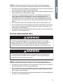
WARNING: For your safety, the information in this manual
must be followed to minimize the risk of fire or explosion,
or to prevent property damage, personal injury, or death.
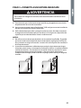
WARNING
To reduce the risk of fire, electric shock, or injury to persons when using
your appliance, follow the basic precautions, including the following:
NOTE: The dryer is designed in compliance with ANSI Z21.5.1 or ANSI/UL
2158 - CAN/CSA C22.2 No. 112-97 (latest editions) for HOME USE ONLY.
This dryer is not recommended for commercial application such as restau-
rants and beauty salons.
• Read all of the instructions before using this appliance.
• This appliance must be properly installed and located in accordance with
the installation instructions before it is used.
• Use this appliance only for its intended purpose as described in this user
manual.
• Do not use the dryer for commercial clothes drying.

3
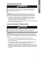
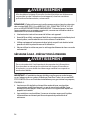
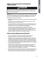
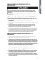
GAS DRYER PRECAUTIONS
WARNING
For your safety, the information in this manual must be followed to
minimize the risk of fire or explosion or to prevent property damage,
personal injury or loss of life.
IMPORTANT: The gas installation must conform with local codes, or in
absence of local codes, with the National Fuel Gas Code, ANSI Z223.1/
NFPA 54, or the Natural Gas and Propane Installation Code, CSA B149.1.
• Installation must be performed by a qualiÞ ed or licensed contractor,
plumber, or gas Þ tter qualiÞ ed or licensed by the state, province, or
region where this appliance is being installed.
• Combustible materials, gasoline, and other ß ammable vapors and liquids
must not be stored near the dryer.
INSTALLATION SAFETY PRECAUTIONS
DANGER
Before you throw away your old appliance, remove the door or lid so
that children cannot hide or get trapped inside your old appliance.
IMPORTANT: The dryer, when installed, must be electrically grounded in
accordance with local codes, or in the absence of local codes, with the Na-
tional Electrical Code, ANSI/NFPA 70, or the Canadian Electrical Code, CSA
C22.1.
• The dryer must be installed by a qualiÞ ed appliance technician.
• Do not install or store this appliance where it will be exposed to water
and/or to the weather.
• The appliance must be properly grounded to conform with all electrical
codes and ordinances. See “Electrical Requirements” section.
• Do not install this dryer to an exhaust system with plastic or metal foil
ß exible ducting. Flexible ducting can collapse, easily be crushed, and trap
lint. These conditions will obstruct clothes dryer airß ow and increase the
risk of Þ re.

4
GENERAL SAFETY PRECAUTIONS
• Keep area around the exhaust opening and adjacent surrounding areas
free from the accumulation of lint, dust and dirt.
• Keep the dryer area clear and free from items that would obstruct
the ß ow of combustion and ventilation air through the louvered panel
located on the rear of the dryer.
• Close supervision is necessary if this appliance is used by or near
children. Do not allow children to play on, with, or inside this appliance.
• Do not dry items that have been previously cleaned in, washed in,
soaked in, or spotted with gasoline, dry-cleaning solvents or other
ß ammable explosive substances, since they give o vapors which could
ignite or explode.
• Do not place items exposed to cooking oils in your dryer. Items
contaminated with cooking oil may contribute to a chemical reaction
than could cause a load to catch Þ re.
• If material has been used with any ß ammable liquids or solids, it should
not be dried in the dryer until all traces of ß ammable liquids and fumes
have been removed.
• Do not reach into the appliance if the drum is moving.
• Do not tamper with the controls.
• Do not use fabric softeners or products to eliminate static unless
recommended by the manufacturers of the fabric softener or product.
• Do not use heat to dry items containing foam rubber or similarly
textured rubber-like materials.
• Clean the lint screen before or after each load.
• The interior of the appliance and the exhaust duct should be cleaned
periodically by qualiÞ ed service personnel.
• To minimize the possibility of electric shock, unplug this appliance from
the power supply before attempting any maintenance or cleaning.
NOTE: Switching o power with the Power button does NOT disconnect
the appliance from the power supply.
• Do not unplug your dryer by pulling on the power cord. Always grasp the
plug Þ rmly and pull straight out from the outlet.
• Do not attempt to service, repair or replace any part of the appliance
unless speciÞ cally recommended in this user manual or in published
repair instructions that you understand and have the skills to carry out.
• Before discarding or removing from service, remove the door to the
drying compartment.
SAVE THESE INSTRUCTIONS
HOUSEHOLD USE ONLY

5
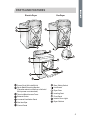
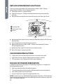
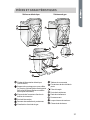
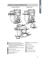
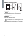
PARTS AND FEATURES
Electric Dryer Gas Dryer
A
B
C
D
E
N
F
K
H
I
J
G
D
E
M
L
Power Cord (120 volt/60 Hz)
Strain Relief Mounting Bracket
(Canadian electric model has a 240 volt/
60 Hz power cord attached.)
Terminal Block Access Cover
Exhaust Outlet
Louvered Ventilation Panel
Gas Inlet Pipe
Control Panel
Door Safety Switch
Lint Screen
Dryer Door
Leveling Feet
Front Panel
Interior Drum Light
Dryer Cabinet

6
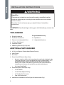
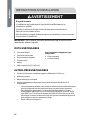
INSTALLATION INSTRUCTIONS
WARNING
Risk of Fire
Clothes dryer installation must be performed by a qualified installer.
Install the clothes dryer according to the manufacturer's instructions
and local codes.
To reduce the risk of severe injury or death, follow all installation
instructions.
IMPORTANT: When discarding or storing your old clothes dryer, remove the
door.
TOOLS NEEDED
• Phillips Screwdriver
• Flat-Blade Screwdriver
• Channel-Lock Adjustable Pliers
• ½" Open-End Wrench
• Carpenter’s Level
• Measuring Tape (12 ft [3.7 m] min.)
For gas installations only:
• Pipe Wrench
• 2 Adjustable Wrenches
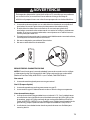
ADDITIONAL PARTS REQUIRED
• 4" (10.2 cm) Rigid or Flexible Metal Exhaust Ducting
• Vent Clamps
• Duct Tape
• Power Cord (US Electric Dryer Only)
- A power supply cord kit must be purchased to meet local electrical codes.
The dryer must use a 3 or 4-wire NEMA 14-30 or 10-30 type SRDT or ST
(as required) power supply cord rated at 120/240 volt AC minimum,
30 amp, with 3 open-end spade lug connectors with upturned ends or
closed loop connectors and marked for use with clothes dryers.
- UL Listed Strain Relief
• Gas Hookup Parts (Gas Dryer Only)
- !" NPT Elbow
- !" NPT Flare Adapter Fitting
- !" Flexible Gas Connector
- Pipe-Joint Compound
• Mobile Home Installation Kit (Gas Dryer for Mobile Home Only)

7
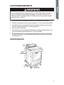
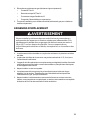
LOCATION REQUIREMENTS
WARNING
Do not install the dryer where gasoline or other flammables are kept or
stored. If the dryer is installed in a garage, it must be a minimum of
18 inches (45.7 cm) above the floor. Failure to do so can result in death,
explosion, fire or burns.
• The dryer must be installed on a solid ß oor. A concrete ß oor is the best.
• The ß oor should be level with maximum slope of 1" (2.5 cm) under entire dryer.
• A suitable location is protected from direct sunlight and heat sources such as
radiators, baseboard heaters, or cooking appliances.
• Do not install on carpeting.
• The location must have the appropriate electrical and gas supply outlets. See
“Electrical & Gas Supply Requirements” section for details.
• Do not install the dryer in an area where the dryer will come into contact with
curtains, thick carpet, or anything that might obstruct the ß ow of combustion
and ventilation air.
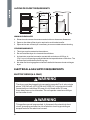
DRYER DIMENSIONS
27"
(68.6 cm)
30
¼"
(77.7 cm)
42½"
(108.0 cm)

8
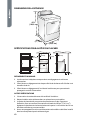
ALCOVE OR CLOSET REQUIREMENTS
60 in.
2
(387.1 cm
2
)
60 in.
2
(387.1 cm
2
)
1"
(2.5 cm)
15"
(38.1 cm)
1"
(2.5 cm)
5½"
(14 cm)
MINIMUM CLEARANCES
• Dimensions shown are the recommended minimum clearance allowances.
• Space on the sides of the dryer is required to avoid noise transfer.
• Space at the rear of the dryer is necessary to accommodate exhaust ducting.
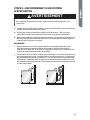
OTHER REQUIREMENTS
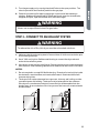
• This dryer must be vented to the outdoors.
• Do not install the dryer in a closet with a solid door.
• A closet door must be louvered or vented with a minimum of 120 sq. in.
(774.2 sq. cm) of opening equally divided at the top and bottom of the door. The
airß ow must not be obstructed in any way.
• No other fuel-burning appliance shall be installed in the same closet as the gas
dryer.
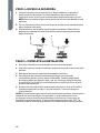
ELECTRICAL & GAS SUPPLY REQUIREMENTS
ELECTRIC DRYER (U.S. ONLY)
WARNING
The dryer must be plugged into a properly grounded 3 or 4-wire, single
phase, 120/240 volt (or 120/208 volt), 60Hz, AC-only electrical outlet
connected to an individual 30-amp circuit, fused with a 30-amp
time-delay fuse or circuit breaker. Do not operate a washer and dryer
on the same circuit.
WARNING
This appliance must be grounded. In the event of an electrical short
circuit, grounding reduces the risk of electric shock by providing an
escape route for the electrical current.

9
NOTE: The electrical supply for the dryer must conform with local codes and
ordinances and the latest edition of the National Electrical Code, ANSI/NFPA 70.
• If the electrical supply available in the intended dryer location does not meet the
above requirements, contact a licensed electrician.
• A dryer operating on a 208 volt power supply will have longer drying times than if
it were operating on a 240 volt power supply.
• The dryer is not equipped with a power cord. A kit that meets local electrical
codes must be purchased separately. The dryer can be Þ tted with a 3 or
4-wire NEMA 14-30 or 10-30 type SRDT or ST (as required) power cord rated
at 120/240 volt AC minimum, 30 amp, with 3 open-end spade lug connectors
with upturned ends or closed loop connectors and marked for use with clothes
dryers.
• A UL listed strain relief must be attached to the dryer to hold the power cord.
• Do not use an aluminum wire receptacle with copper-wired power cord and plug
(or vice versa). The proper wiring and receptacle is a copper-wired power cord
with a copper-wired receptacle.
• The electrical outlet should be located so that the power cord is accessible when
the dryer is in the installed position.
ELECTRIC DRYER (CANADA ONLY)
WARNING
The dryer must be plugged into a properly grounded 4-wire, single
phase, 120/240 volt, 60Hz, AC-only electrical outlet connected to an
individual 30-amp circuit, fused with a 30-amp time-delay fuse or
circuit breaker. Do not operate a washer and dryer on the same circuit.
WARNING
This appliance must be grounded. In the event of an electrical short
circuit, grounding reduces the risk of electric shock by providing an
escape route for the electrical current.
NOTE: The electrical service to the dryer must conform with local codes and
ordinances and the latest edition of the CSA C22.1 Canadian Electrical Code Part 1.
• If the electrical supply available in the intended dryer location does not meet the
above requirements, contact a licensed electrician.
• Do not use an aluminum wire receptacle with copper-wired power cord and plug
(or vice versa). The proper wiring and receptacle is a copper-wired power cord
with a copper-wired receptacle.
• The electrical outlet should be located so that the power cord is accessible when
the dryer is in the installed position.

10
GAS DRYER
ELECTRICAL SUPPLY REQUIREMENTS
WARNING
The gas dryer must be plugged into a properly grounded 3-wire, single
phase, 120 volt, 60Hz, AC-only electrical outlet, fused with a 15-amp
time-delay fuse or circuit breaker.
WARNING
This appliance must be grounded. In the event of an electrical short
circuit, grounding reduces the risk of electric shock by providing an
escape route for the electrical current.
• The dryer is equipped with a power cord that has a 3 prong plug. Do not cut or
remove the grounding prong from the power cord.
• The power cord must be plugged into a mating, 3 prong outlet, grounded in
accordance with local codes and ordinances. If a mating outlet is not available,
contacted a licensed electrician to have one installed.
• If you are not sure if your outlet is properly grounded, contact a licensed
electrician.
• Do not use a 3 prong plug adapter.
• Do not use an extension cord.
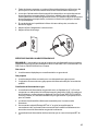
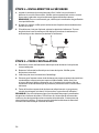
GAS SUPPLY REQUIREMENTS
NOTE: The gas service to the dryer must conform with local codes and ordinances
and the latest edition of the National Fuel Gas Code, ANSI Z223.1 or in Canada,
CAN/CGA B149.1.
Natural Gas
• The dryer is equipped for use with Natural gas.
LP (Liquid Propane) Gas
• The dryer can be converted for use with LP gas.
• Conversion to LP gas must be made by a qualiÞ ed technician.

11
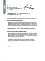
Gas Supply Line
• The gas supply line should be ½" (1.3 cm) pipe and must have an individual
manual shuto valve installed within 6 ft (183 cm) of the dryer in accordance with
the National Fuel Gas Code, ANSI Z223.1/NFPA 54, or in Canada with the Natural
Gas and Propane Installation Code, B149.1.
• The shuto valve should be easy to reach for opening and closing.
• A "" NPT minimum plugged tapping, accessible for test gage connection, must
be installed immediately upstream of the gas supply connection to the dryer.
• The supply line should terminate with a !" NPT ß are adapter Þ tting.
½" NPT Gas Supply Line
Gas Shuto Valve
"" NPT Minimum Plugged Tapping
!" NPT Flare Adapter Fitting
B
C
D
A
GAS SUPPLY CONNECTION REQUIREMENTS
This dryer must be connected to the gas supply line with a listed ß exible gas
connector that complies with the standard for connectors for gas appliances, ANSI
Z21.24 or CSA 6.10.
Flexible stainless steel gas connector:
• If local codes permit, use a new ß exible stainless steel gas connector (Design
CertiÞ ed by the American Gas Association or CSA International) to connect your
dryer to the rigid gas supply line. Use an elbow and a !" ß are x !" NPT adapter
Þ tting between the stainless steel gas connector and the dryer gas pipe, as
needed to prevent kinking.
BURNER INPUT REQUIREMENTS
Elevations up to 10,000 ft. (3,048 m):
• The design of this dryer is certiÞ ed by CSA International for use at altitudes up to
10,000 ft. (3,048 m), above sea level at the B.T.U. rating indicated on the model/
serial number plate. Burner input adjustments are not required when the dryer is
operated up to this elevation.
Elevations above 10,000 ft. (3,048 m):
• When installed above 10,000 ft. (3,048 m) a 4% reduction of the burner B.T.U.
rating shown on the model/serial number plate is required for each 1,000 ft.
(305 m) increase in elevation.
Gas supply pressure testing:
• The dryer must be disconnected from the gas supply piping system during
pressure testing at pressures greater than 1/2 psi (3.5kPa).

12
EXHAUST SYSTEM REQUIREMENTS
WARNING
This section describes the requirements for a safe and efficient exhaust
system. Failure to follow these instructions can result in poor dryer
performance, damage to the dryer, and a fire hazard.
IMPORTANT: The dryer must be exhausted to the outdoors.
• The dryer shall not be exhausted into any gas vent, chimney, wall, ceiling, or
concealed space of a building.
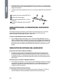
DUCTING
• If your current exhaust system is constructed of plastic or metal foil ß exible
ducting, replace it with rigid metal ducting.
• Use only 4” (10.2 cm) diameter rigid metal ducting.
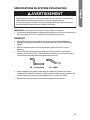
• When making turns in the ductwork, use 45° elbows rather than 90° elbows. This
provides better airß ow and can reduce the accumulation of lint in the exhaust
system.
90° - Good 45° - Better
• Do not exceed the length of duct pipe for the number of elbows shown in the
chart below. Doing so can cause an accumulation of lint, an increase in drying
time, and the creation of a Þ re hazard.
• Two 45° elbows equal one 90° elbow.

13
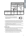
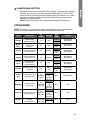
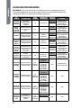
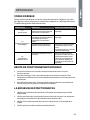
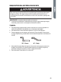
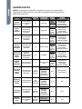
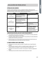
Recommended Maximum Exhaust Length
Exhaust Hood Types
Recommended Use Only For Short Run
Installations
4"
(10.2 cm)
dia.
4"
(10.2 cm)
4"
(10.2 cm)
dia.
2½"
(6.4 cm)
4"
(10.2 cm)
dia.
No. of 90° Elbows Rigid Metal Rigid Metal
0
1
2
3
90 feet
60 feet
45 feet
35 feet
60 feet
45 feet
35 feet
25 feet
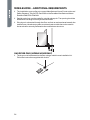
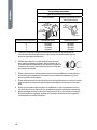
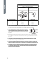
• All joints should be tight to avoid air leaks. The male end of each section of
ducting must point away from the dryer.
• Use clamps or duct tape to connect and seal all joints.
Do not connect with screws or other fasteners that
extend into the interior of the duct as they will create a
collection point for lint.
Clamp
• Avoid running the exhaust system through an unheated area as this will cause
condensation to form inside the duct and increase the rate of lint accumulation.
• Avoid running the exhaust system vertically through a roof as this may expose
the exhaust system to down drafts, causing an increase in air restriction.
• Avoid sagging, compression or crimping of the exhaust system as this will result
in reduced airß ow and poor dryer performance.
• Do not screen the end of the exhaust system. Lint will accumulate and
eventually clog the screen. Use an approved exhaust hood to terminate the duct
outdoors.
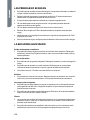
EXHAUST HOOD
• Use an approved exhaust hood with a swing-out damper that opens when the
dryer is in operation. When the dryer stops, the damper automatically closes to
prevent drafts and the entrance of insects and rodents.
• Louvered or box hood styles are recommended. Angled hood styles are
acceptable, but should be used only for short run installations. See the
“Recommended Maximum Exhaust Length” chart for more information.
• To avoid restricting airß ow, maintain a minimum of 12” (30.5 cm) clearance
between the vent hood and the ground or any other obstruction.

14
MOBILE HOME - ADDITIONAL REQUIREMENTS
• The installation must conform to current Manufactured Home Construction and
Safety Standard, Title 24 CFR-Part 3280 or the Canadian Manufactured Home
Standard CAN/CSA-Z240 MH.
• Special provisions must be made for outside makeup air. The opening should be
at least twice as large as the dryer exhaust outlet.
• If the dryer is exhausted through the ß oor and into an enclosed area beneath the
mobile home, the exhaust system must terminate outside the enclosure with
the termination securely fastened to the mobile home structure.
GAS DRYER ONLY (MOBILE HOME ONLY)
• The dryer must be fastened to the ß oor using a mobile home installation kit.
Follow the instructions supplied with the kit.

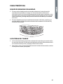
15
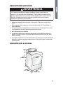
STEP BY STEP INSTRUCTIONS
INSTALLING YOUR DRYER
We recommend that your new dryer be installed by a qualiÞ ed appliance technician.
If you feel that you have the skills to install the dryer, please read the installation
instructions thoroughly before installing.
CAUTION: If, after completing these steps, you are unsure that the dryer is properly
installed, contact a qualiÞ ed appliance technician.
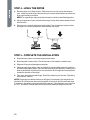
STEP 1 - UNPACK THE DRYER
1. Remove all packing materials. This includes the foam base and all adhesive tape
holding the dryer accessories inside and outside.
2. Inspect and remove any remains of packing, tape or printed materials before
using the dryer.
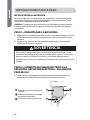
WARNING
To avoid danger of suffocation, keep plastic bag and other packing
material away from babies and children. Do not use this bag in cribs,
carriages and playpens. The plastic bag could block nose and mouth
and prevent breathing. This bag is not a toy.
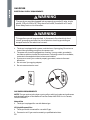
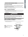
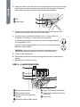
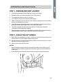
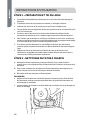
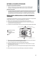
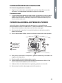
STEP 2 - ATTACH A POWER CORD TO THE DRYER
(ELECTRIC DRYER - U.S. ONLY)
1. Remove the screw securing the terminal block access cover, located on the back
of the dryer’s upper corner.
Terminal Block Access Cover
Hole in Strain Relief Mounting
Bracket
Access Cover Screw
A
B
C

16
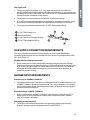
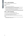
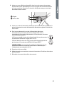
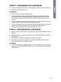
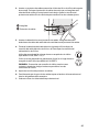
2. Insert a UL listed strain relief into the mounting bracket hole. Position the strain
relief so that one tab is pointing up and one tab is pointing down. Tighten the
strain relief screws just enough to hold the two halves together.
Tab
Strain Relief
A
B
3. Insert a power cord into the strain relief. Take care to ensure that the wire
insulation of the power cord is inside the strain relief.
4. Connect power cord wires following Part A for a 4-wire power cord
connection or Part B for a 3-wire power cord connection.
4-wire (recommended) if your home has a 4-wire receptacle (NEMA
14-30 type SRDT or ST):
3-wire (if 4-wire is not available) if your home has a 3-wire receptacle
(NEMA 10-30 type SRDT):
CAUTION: A 4-wire connection is required for mobile homes and
where local codes do not permit the use of 3-wire connections.
5. Tighten strain relief screws.
6. Be sure that none of the wires are touching the dryer drum inside the dryer
cabinet.
7. Reinstall the terminal block cover.
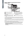
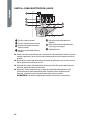
PART A - 4-WIRE POWER CORD
A
B
C
F
E
G
D
Ground Screw (Green)
Terminal Block Screw
Neutral-Ground Jumper Wire
(Green)
Power Cord Ground Wire (Green)
Power Cord Neutral Wire (White)
Power Cord Line Wires (One Red;
One Black)
Power Cord

17
A1. Remove the green ground screw connecting the neutral-ground jumper wire
(green) to the cabinet and the center terminal block screw, then discard the
jumper wire.
A2. Attach the power cord ground wire (green) to the cabinet with the green ground
screw. Tighten the screw securely.
A3. Attach the power cord neutral wire (white) with the center terminal block screw.
Tighten the screw securely.
A4. Attach the remaining 2 power cord line wires (red and black) with the outer
terminal block screws. Attach one wire to each terminal block as shown. Tighten
both screws securely.
IMPORTANT: Do not make a sharp bend or crimp the wires at connections.
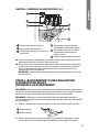
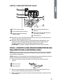
PART B - 3-WIRE POWER CORD
A
B
C
E
D
F
Ground Screw (Green)
Terminal Block Screw
Neutral-Ground Jumper Wire
(Green)
Power Cord Neutral Wire (White)
Power Cord Line Wires (One Red;
One Black)
Power Cord
B1. Attach the power cord neutral wire (white) to the center terminal block screw.
Tighten the screw securely.
B2. Attach the remaining 2 power cord line wires (red and black) with the outer
terminal block screws. Attach one wire to each terminal block as shown. Tighten
both screws securely.
IMPORTANT: Do not make a sharp bend or crimp the wires at connections.

18
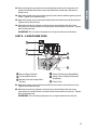
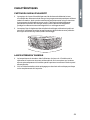
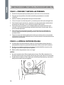
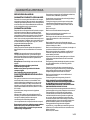
STEP 2 - CONNECT TO A GAS SUPPLY LINE
(GAS DRYER ONLY)
NOTE: Do not connect the dryer to an LP gas line without Þ rst converting the
dryer with a conversion kit. An LP conversion kit must be installed by a qualiÞ ed
technician.
NOTE: Apply a pipe-joint compound that that is resistant to the action of LP gas to
all males threads. Do not use plumber’s tape.
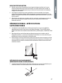
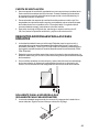
1. Turn the gas supply o by moving the shuto valve to the closed position.
Closed Valve
Open Valve
A
B
2. Disconnect and discard old ß exible gas connector. Replace with a new
CSA(AGA) approved ß exible gas connector.
3. Remove the shipping cap from the gas inlet pipe at the rear of the dryer.
4. Connect a !" NPT elbow to the gas inlet pipe on the dryer. Then connect a ß are
adapter to the elbow.
IMPORTANT: Use a pipe wrench to keep the dryer gas inlet pipe from twisting.
Gas Inlet Pipe on
the Dryer
!" NPT Elbow
!" NPT Flare Adapter
A
B
C
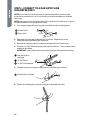
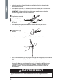
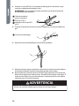
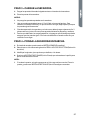
5. Connect the dryer to the gas supply line with a ß exible gas connector.
Flexible Gas Connector
A
6. Tighten the ß exible gas connector using two adjustable wrenches.
La page est en cours de chargement...
La page est en cours de chargement...
La page est en cours de chargement...
La page est en cours de chargement...
La page est en cours de chargement...
La page est en cours de chargement...
La page est en cours de chargement...
La page est en cours de chargement...
La page est en cours de chargement...
La page est en cours de chargement...
La page est en cours de chargement...
La page est en cours de chargement...
La page est en cours de chargement...
La page est en cours de chargement...
La page est en cours de chargement...
La page est en cours de chargement...
La page est en cours de chargement...
La page est en cours de chargement...
La page est en cours de chargement...
La page est en cours de chargement...
La page est en cours de chargement...
La page est en cours de chargement...
La page est en cours de chargement...
La page est en cours de chargement...
La page est en cours de chargement...
La page est en cours de chargement...
La page est en cours de chargement...
La page est en cours de chargement...
La page est en cours de chargement...
La page est en cours de chargement...
La page est en cours de chargement...
La page est en cours de chargement...
La page est en cours de chargement...
La page est en cours de chargement...
La page est en cours de chargement...
La page est en cours de chargement...
La page est en cours de chargement...
La page est en cours de chargement...
La page est en cours de chargement...
La page est en cours de chargement...
La page est en cours de chargement...
La page est en cours de chargement...
La page est en cours de chargement...
La page est en cours de chargement...
La page est en cours de chargement...
La page est en cours de chargement...
La page est en cours de chargement...
La page est en cours de chargement...
La page est en cours de chargement...
La page est en cours de chargement...
La page est en cours de chargement...
La page est en cours de chargement...
La page est en cours de chargement...
La page est en cours de chargement...
La page est en cours de chargement...
La page est en cours de chargement...
La page est en cours de chargement...
La page est en cours de chargement...
La page est en cours de chargement...
La page est en cours de chargement...
La page est en cours de chargement...
La page est en cours de chargement...
La page est en cours de chargement...
La page est en cours de chargement...
La page est en cours de chargement...
La page est en cours de chargement...
La page est en cours de chargement...
La page est en cours de chargement...
La page est en cours de chargement...
La page est en cours de chargement...
La page est en cours de chargement...
La page est en cours de chargement...
La page est en cours de chargement...
La page est en cours de chargement...
La page est en cours de chargement...
La page est en cours de chargement...
La page est en cours de chargement...
La page est en cours de chargement...
La page est en cours de chargement...
La page est en cours de chargement...
La page est en cours de chargement...
La page est en cours de chargement...
La page est en cours de chargement...
La page est en cours de chargement...
La page est en cours de chargement...
La page est en cours de chargement...
-
 1
1
-
 2
2
-
 3
3
-
 4
4
-
 5
5
-
 6
6
-
 7
7
-
 8
8
-
 9
9
-
 10
10
-
 11
11
-
 12
12
-
 13
13
-
 14
14
-
 15
15
-
 16
16
-
 17
17
-
 18
18
-
 19
19
-
 20
20
-
 21
21
-
 22
22
-
 23
23
-
 24
24
-
 25
25
-
 26
26
-
 27
27
-
 28
28
-
 29
29
-
 30
30
-
 31
31
-
 32
32
-
 33
33
-
 34
34
-
 35
35
-
 36
36
-
 37
37
-
 38
38
-
 39
39
-
 40
40
-
 41
41
-
 42
42
-
 43
43
-
 44
44
-
 45
45
-
 46
46
-
 47
47
-
 48
48
-
 49
49
-
 50
50
-
 51
51
-
 52
52
-
 53
53
-
 54
54
-
 55
55
-
 56
56
-
 57
57
-
 58
58
-
 59
59
-
 60
60
-
 61
61
-
 62
62
-
 63
63
-
 64
64
-
 65
65
-
 66
66
-
 67
67
-
 68
68
-
 69
69
-
 70
70
-
 71
71
-
 72
72
-
 73
73
-
 74
74
-
 75
75
-
 76
76
-
 77
77
-
 78
78
-
 79
79
-
 80
80
-
 81
81
-
 82
82
-
 83
83
-
 84
84
-
 85
85
-
 86
86
-
 87
87
-
 88
88
-
 89
89
-
 90
90
-
 91
91
-
 92
92
-
 93
93
-
 94
94
-
 95
95
-
 96
96
-
 97
97
-
 98
98
-
 99
99
-
 100
100
-
 101
101
-
 102
102
-
 103
103
-
 104
104
-
 105
105
-
 106
106


Haier CGDE560BW Manuel utilisateur
- Catégorie
- Sèche-linge électriques
- Taper
- Manuel utilisateur
dans d''autres langues
- English: Haier CGDE560BW User manual
- español: Haier CGDE560BW Manual de usuario