
RIO-CONTROL
RIO-EDGE
RIO-LUX
RIO-CELL
RIO-CELL
RIO-CELL
RIO-EDGE
RIO-CELL
RIO-CONTROL
RIO-CELL
RIO-CELL
10 2 E TS
10 2 E TS
10 2 E TS
230 V
OUT1 OUT2 OUT3 OUT4
80
A
E
C D
B
10 2 E TS OUT1
LAMP 230 VAC
WIRELESS
CH1
CH2
PROG
RESET
OUT2 OUT3 OUT4
LH
LH
Jumper LH
③
①
②
⑦
⑧
⑩
⑤
⑨
④
⑥
IP54
140
110
50
OUT1 OUT2 OUT3 OUT4
10 2 E TS
OUT1 OUT2 OUT3 OUT4
10 2 E TS
LAMP 230V AC
10 11 1 2 3P 75 2 C1 U V W E1C7C3 TSC8
10 11 1E1 2 3P 75 2 C1 C7C3 TSC8
24 V
RIO-CONTROL
RIO-CONTROL
230 V
OUT1 OUT2 OUT3 OUT4
10 2 E TS
OUT1 OUT2 OUT3 OUT4
10 2 E TS
LAMP 230V AC
10 11 1 2 3P 75 2 C1 U V W E1C7C3 TSC8
10 11 1E1 2 3P 75 2 C1 C7C3 TSC8
24 V
RIO-CONTROL
RIO-CONTROL
230 V
⑪
⑫
⑬
⑭
⑮
⑯
-20°C
55°C
FA00107M4A - ver. 1 - 05/2015
FA00107M4A
ITALIANO
Descrizione
Dispositivo per la gestione via radio di accessori della serie wireless
Rio (max 10 unità).
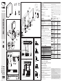
Nella figura di esempio A, sono rappresentate 9 unità interfacciate
a Rio-Control.
Componenti principali della scheda E
③ Antenna.
④ Buzzer.
⑤ Selettore di potenza radio.
⑥ LED di segnalazione.
⑦ Pulsante di programmazione.
⑧ Pulsante di reset.
⑨ Ingresso lampeggiatore.
⑩ Morsettere di connessione al quadro (vedi figura C D).
Dati tecnici
Tipo RIO-CONTROL
Alimentazione (V) 24 AC/DC
Assorbimento max (mA) 80
Contatti relè a 24 V max (A) 1
Portata radio in campo libero (m) 30 max.
Frequenza (MHz) 868.95 - 869.85
Installazione
⚠ Prima di procedere TOGLIERE LA TENSIONE DI LINEA e, se pre-
senti nell'automazione, scollegare le batterie.
Montaggio del contenitore e della scheda B
•Con l'aiuto di un trapano aprire i fori presfondati necessari per il
passaggio dei cavi B ①.
•Fissare il contenitore, utilizzando tasselli e/o viti adeguate alla su-
perficie.
•Inserire la scheda facendola scorrere nell'apposita guida.
NB: Non modificare la posizione dell'antenna.
•Dopo avere eseguito il cablaggio (vedi esempio figura C), ali-
mentare l’automazione e verificare che i LED blu [WIRELESS] lam-
peggino. Se non lampeggiano, eseguire un Reset della scheda (vedi
relativa procedura).
•Togliere le batterie dagli accessori.
•Memorizzare ogni singolo componente del sistema (vedi istruzioni
degli accessori).
•Verificare la funzionalità del sistema (vedi relativa procedura) e
chiudere il coperchio fissandolo alla base con la vite in dotazione
B ②.
Descrizione morsettiera C D
10-2 Ingresso alimentazione 24 V AC/DC ⑬
10-E Ingresso lampeggiatore 24 V AC/DC ⑭
TS Ingresso test sicurezza
(se non usato ponticellare con 2) ⑯
IN1 - IN2 Non utilizzato
OUT1 (NC) Uscita attivata dall'ingresso IN1 di RIO EDGE me-
morizzato con T1.
OUT2 (NC) Uscita attivata dall'ingresso IN2 di RIO EDGE me-
morizzato con T2.
OUT3 (NC) Uscita attivata da RIO CELL memorizzato con T1.
OUT4 (NC) Uscita attivata da RIO CELL memorizzato con T2.
OUT5 (NC) Non utilizzato
LAMP-230 V Ingresso lampeggiatore a 230 V ⑮
⚠ Non è possibile collegare contemporaneamente lampeggiatori
agli ingressi a 24 V AC/DC ⑭ e 230 V AC ⑮.
Collegamento ai quadri di comando C
⚠ Collegare sempre il morsetto LAMP ai morsetti W-E1 dei quadri
a 230 V C ⑪ o l'ingresso 10-E di RIO-CONTROL ai morsetti 10-E
o 10-E1 dei quadri a 24 V C ⑫.
☞ Abilitare sempre il pre-lampeggio.
☞ Abilitare il test servizi (se presente).
☞ Evitare in generale quelle condizioni in cui ad automazione
ferma il lampeggiatore sia attivo.
Per esempio con funzione C4 abilitata sul quadro CAME, in caso di
fotocellula impegnata, gli accessori RIO resteranno attivi per tutto
il periodo di intervento riducendo la durata delle batterie.
Reset della scheda
Tenere premuto il tasto di reset [RESET] per circa 10 secondi, fino a
quando lampeggeranno i LED [WIRELESS].
NB La sostituzione di un dispositivo comporta il reset e la suc-
cessiva rimemorizzazione di tutti i dispositivi del sistema.
Verifiche funzionali
Dare un comando di avvio manovra all’automazione (ogni accessorio
Rio emette* un lampeggio blu)
Verificare che Rio-Lux si attivi.
Provocare una interferenza sulla manovra del cancello e verificare
che i dispositivi Rio-Cell e/o Rio-Edge attivino la funzione di sicurezza
prevista.
Al termine della manovra, ogni accessorio Rio emetterà* un lampeg-
gio rosso ed entrerà in modalità Low Power per preservare lo stato
delle batterie.
⚠ NB: in modalità Low Power, la risposta al test manuale di fun-
zionamento delle fotocellule (un lampeggio blu del LED), risulterà
essere più lenta.
* Se ciò non accade, togliere la tensione di linea e aumentare la
portata/potenza del segnale radio mettendo il jumper E ⑤ in
posizione H.
Soluzione dei problemi
LED acceso fisso, LED spento, LED lampeggiante
Buzzer ON, Buzzer OFF
Segnalazioni Possibili cause Soluzione
WIRELESS
CH1
CH2
WIRELESS
CH1
CH2
WIRELESS
CH1
CH2
WIRELESS
CH1
CH2
WIRELESS
CH1
CH2
WIRELESS
CH1
CH2
WIRELESS
CH1
CH2
Morsetto TS
(test sicurezze) non
cablato.
Collegare il morsetto TS
al corrispondente sul
quadro. In assenza di cor-
rispondente sul quadro,
collegare al morsetto 2.
WIRELESS
CH1
CH2
WIRELESS
CH1
CH2
WIRELESS
CH1
CH2
WIRELESS
CH1
CH2
WIRELESS
CH1
CH2
WIRELESS
CH1
CH2
WIRELESS
CH1
CH2
Nessun accessorio RIO
memorizzato.
Configurare gli accessori
RIO.
WIRELESS
CH1
CH2
WIRELESS
CH1
CH2
WIRELESS
CH1
CH2
WIRELESS
CH1
CH2
WIRELESS
CH1
CH2
WIRELESS
CH1
CH2
WIRELESS
CH1
CH2
Il bordo sensibile
collegato su IN1di
RIO-EDGE non inter-
viene.
Verificare collegamenti
e regolazioni del bordo
sensibile.
WIRELESS
CH1
CH2
WIRELESS
CH1
CH2
WIRELESS
CH1
CH2
WIRELESS
CH1
CH2
WIRELESS
CH1
CH2
WIRELESS
CH1
CH2
WIRELESS
CH1
CH2
Il bordo sensibile
collegato su IN2
di RIO-EDGE non
interviene.
Verificare collegamenti
e regolazioni del bordo
sensibile.
WIRELESS
CH1
CH2
WIRELESS
CH1
CH2
WIRELESS
CH1
CH2
WIRELESS
CH1
CH2
WIRELESS
CH1
CH2
WIRELESS
CH1
CH2
WIRELESS
CH1
CH2
Le Rio-Cell memorizzate con T1:
a. Rilevano un
ostacolo.
b. Sono disallineate.
c. Hanno le batterie
scariche.
a. Rimuovere l'ostacolo.
b. Allineare le fotocellule.
c. Sostituire le batterie.
WIRELESS
CH1
CH2
WIRELESS
CH1
CH2
WIRELESS
CH1
CH2
WIRELESS
CH1
CH2
WIRELESS
CH1
CH2
WIRELESS
CH1
CH2
WIRELESS
CH1
CH2
Le Rio-Cell memorizzate con T2:
a. Rilevano un
ostacolo.
b. Sono disallineate.
c. Hanno le batterie
scariche.
a. Rimuovere l'ostacolo.
b. Allineare le fotocellule.
c. Sostituire le batterie.
WIRELESS
CH1
CH2
WIRELESS
CH1
CH2
WIRELESS
CH1
CH2
WIRELESS
CH1
CH2
WIRELESS
CH1
CH2
WIRELESS
CH1
CH2
WIRELESS
CH1
CH2
RIO-EDGE o RIO-CELL
non comunicano con
RIO-CONTROL.
Verificare l’ecienza della
trasmissione radio.
Assicurarsi che le batterie
non siano scariche.
3 beep.
RIO-LUX lam-
peggia 3 volte
rapidamente.
Le batterie di uno o
più dispositivi radio
connessi risultano
quasi scariche.
Verificare lo stato delle
batterie dei dispositivi
radio connessi e sostituirle
entro 10 giorni.
Riferimenti normativi. RIO-CONTROL abbinato a RIO-EDGE e insieme ad una au-
tomazione (o quadro comando) con test di sicurezza abilitato, è un dispositivo di
sicurezza di categoria 2 (EN 954-1).
A installazione ultimata, verificare la conformità alle parti applicabili delle norme EN
13241-1, EN 12453, EN 12445.
Came S.p.A. non può considerarsi responsabile per eventuali danni causati da un
uso improprio, erroneo o irragionevole del prodotto.
Il prodotto è conforme alle direttive di riferimento vigenti.
Dismissione e smaltimento. Non disperdere nell’ambiente l’imballaggio e il dispo-
sitivo alla fine del ciclo di vita, ma smaltirli seguendo le norme vigenti nel paese di
utilizzo del prodotto. I componenti riciclabili riportano simbolo e sigla del materiale.
I DATI E LE INFORMAZIONI INDICATE IN QUESTO MANUALE SONO DA RITENERSI SU-
SCETTIBILI DI MODIFICA IN QUALSIASI MOMENTO E SENZA OBBLIGO DI PREAVVISO.
LE MISURE, SE NON DIVERSAMENTE INDICATO, SONO IN MILLIMETRI.

FA00107M4A - ver. 1 - 05/2015
ENGLISH
Description
Device for managing up to 10 RIO-series accessories via radio.
Figure A shows nine units interfaced with RIO-CONTROL.
Main control-card components E
③ Antenna.
④ Buzzer.
⑤ Radio power-range selector switch.
⑥ Warning LED.
⑦ Programming button.
⑧ Reset button.
⑨ Flashing light input.
⑩ Terminals for connecting to the control panel (see figure C D).
Technical data
Type RIO-CONTROL
Power supply (V) 24 AC/DC
Maximum draw (mA) 80
Relay contacts 24 V max. (A) 1
Radio range over clear areas (m) 30 max.
Frequency (MHz) 868.95 - 869.85
Installation
⚠ Before continuing, cut o the MAINS POWER SUPPLY and dis-
connect any batteries.
Fitting the casing and control card B
• Drill the pre-punched holes needed for passing through the cables
B ①.
• Fasten the casing, using dowels and/or screws suitable for the
surface.
• Fit the card and slide it along the corresponding rail guide.
NB: Do not change the antenna's position.
• After connecting the cables (see example in figure C), power up
the system and check that the blue wireless LEDs are flashing. If
they are not flashing, reset the card (see corresponding procedure).
• Remove batteries from the accessories.
• Memorize each single component of the system (see accessories
instructions).
• Test system's functionality (see corresponding procedure) and
close the cover by fastening it to the base using the supplied screw
B ②.
Description of terminal board C D
10-2 Power supply input 24 V AC/DC ⑬
10-E Flashing light input 24 V AC/DC ⑭
TS Safety-test input
(if unused, bridge with 2) ⑯
IN1 - IN2 Not used
OUT1 (NC) Output activated by input IN1 of RIO EDGE memo-
rized on T1.
OUT2 (NC) Output activated by input IN2 of RIO EDGE memo-
rized on T2.
OUT3 (NC) Output activated by RIO CELL memorized on T1.
OUT4 (NC) Output activated by RIO CELL memorized on T2.
OUT5 (NC) Not used
LAMP-230 V Flashing light input at 230 V ⑮
⚠ You cannot simultaneously connect the flashing lights to the
24 V AC/DC and ⑭ 230 V AC inputs ⑮.
Connection to the control panels. C
⚠ Always connect the LAMP terminal to the W-E1 terminals on
the 230 V panels C ⑪ or the RIO-CONTROL 10-E input to the
10-E or 10-E1 terminals of the 24 V panels C ⑫.
☞ Always enable the pre-flashing.
☞ Enable the services test (if present).
☞ Generally avoid those conditions in which when the operator is
idle the flashing light is active.
For example, with function C4 enabled on the CAME panel, if the
photocell is engaged, the RIO accessories shall remain active for
the entire intervention period, thus reducing battery life.
Card resetting
Keep the RESET button pressed for about 10 seconds, the wireless
LEDs flash.
NB: Replacing a device means that you will have to reset the
card and again memorize all the devices on the system.
Functional checks
Press a command button (each Rio accessory flashes* blue)
Check that RIO-LUX activates.
Obstruct the gate's action and check whether the RIO-CELL and/or
RIO-EDGE devices actually activate prescribed safety function.
When the maneuver ends, each Rio accessory will flash* red and
then go into Low Power mode to preserve the batteries.
⚠ NB: In Low-Power mode, the manual test response time (that
is, the flashing blue LED), will be slower.
* If this does not happen, cut o the mains power supply and
increase the radio signal's range/power by setting the jumper E
⑤ to position H.
Troubleshooting
LED permanently glowing, LED switched o, LED flashes
Buzzer ON, Buzzer OFF
Warnings Possible causes Fix
WIRELESS
CH1
CH2
WIRELESS
CH1
CH2
WIRELESS
CH1
CH2
WIRELESS
CH1
CH2
WIRELESS
CH1
CH2
WIRELESS
CH1
CH2
WIRELESS
CH1
CH2
TS terminal (safety
devices test) not wired.
Connect the TS terminal
to the corresponding one
on the panel. If the cor-
responding one is lacking
on the panel, connect it to
terminal 2.
WIRELESS
CH1
CH2
WIRELESS
CH1
CH2
WIRELESS
CH1
CH2
WIRELESS
CH1
CH2
WIRELESS
CH1
CH2
WIRELESS
CH1
CH2
WIRELESS
CH1
CH2
No Rio accessory is
memorized.
Configure RIO acces-
sories.
WIRELESS
CH1
CH2
WIRELESS
CH1
CH2
WIRELESS
CH1
CH2
WIRELESS
CH1
CH2
WIRELESS
CH1
CH2
WIRELESS
CH1
CH2
WIRELESS
CH1
CH2
The sensitive edge
connected to IN1 of
RIO-EDGE fails to
intervene.
Check settings and ad-
justments on the sensitive
safety-edge.
WIRELESS
CH1
CH2
WIRELESS
CH1
CH2
WIRELESS
CH1
CH2
WIRELESS
CH1
CH2
WIRELESS
CH1
CH2
WIRELESS
CH1
CH2
WIRELESS
CH1
CH2
The sensitive safe-
ty-edge connected to
IN2 on RIO-EDGE fails
to intervene.
Check settings and ad-
justments on the sensitive
safety-edge.
WIRELESS
CH1
CH2
WIRELESS
CH1
CH2
WIRELESS
CH1
CH2
WIRELESS
CH1
CH2
WIRELESS
CH1
CH2
WIRELESS
CH1
CH2
WIRELESS
CH1
CH2
The Rio-Cells memorized with T1:
a. Detect an obstruc-
tion.
b. Are misaligned.
c. Have flat batteries.
a. Remove the obstruc-
tion.
b. Align the photocells.
c. Replace the batteries.
WIRELESS
CH1
CH2
WIRELESS
CH1
CH2
WIRELESS
CH1
CH2
WIRELESS
CH1
CH2
WIRELESS
CH1
CH2
WIRELESS
CH1
CH2
WIRELESS
CH1
CH2
The Rio-Cells memorized with T2:
a. Detect an obstruc-
tion.
b. Are misaligned.
c. Have flat batteries.
a. Remove the obstruc-
tion.
b. Align the photocells.
c. Replace the batteries.
WIRELESS
CH1
CH2
WIRELESS
CH1
CH2
WIRELESS
CH1
CH2
WIRELESS
CH1
CH2
WIRELESS
CH1
CH2
WIRELESS
CH1
CH2
WIRELESS
CH1
CH2
RIO-EDGE or RIO-CELL
is not communicating
with RIO-CONTROL.
Check the radio-transmis-
sion eciency.
Make sure the batteries
are charged.
3 beeps.
RIO-LUX
flashes quickly
3 times.
The batteries on one or
more of the connected
wireless devices are
almost flat.
Check the status of the
batteries on the connect-
ed wireless devices and
replace them within 10
days.
Pertinent Regulations. RIO-CONTROL paired with RIO-EDGE together with an op-
erator (or control panel) with safety test enabled, is a category 2 safety device (EN
954-1).
Once installed, check compliance with the applicable parts of the following regula-
tions: EN 13241-1, EN 12453, EN 12445.
Came S.p.A. is not liable for any damage caused if the product is used improperly,
wrongfully or unreasonably.
The product complies with the relevant directives in force.
Decommissioning and disposal. - Do not dispose of the packaging and the device,
at the end of its life cycle, in nature, but rather dispose of them by following the ap-
plicable laws in the country where the device is installed. The recyclable components
all bear a symbol to that eect.
THE DATA AND INFORMATION IN THIS MANUAL MAY BE CHANGED AT ANY TIME
AND WITHOUT NOTICE.
THE MEASUREMENTS, UNLESS OTHERWISE STATED, ARE IN MILLIMETERS.
FRANÇAIS
Description
Dispositif pour la gestion radio d'accessoires de la série sans fil Rio
(10 unités max.).
L'exemple de la figure A représente 9 unités interfacées avec le
Rio-Control.
Principaux composants de la carte E
③ Antenne.
④ Buzzer.
⑤ Sélecteur de puissance radio.
⑥ Voyants de signalisation.
⑦ Bouton de programmation.
⑧ Bouton RàZ.
⑨ Entrée feu clignotant.
⑩ Bornier de connexion au tableau (voir figure C D).
Données techniques
Type RIO-CONTROL
Alimentation (V) 24 AC/DC
Absorption max. (mA) 80
Contacts relais à 24 V max. (A) 1
Portée radio en champ libre (m) 30 max.
Fréquence (MHz) 868.95 - 869.85
Installation
⚠ Avant de procéder à l'installation, METTRE HORS TENSION et
déconnecter les éventuelles batteries de l'automatisme.
Montage du boîtier et de la carte B
• Ouvrir, à l'aide d'une perceuse, les trous préforés prévus pour le
passage des câbles B ①.
• Fixer le boîtier à la surface à l'aide des chevilles et/ou des vis
appropriées.
• Introduire la carte en la faisant glisser dans le guide spécifique.
NB : ne pas modifier la position de l'antenne.
• Après avoir eectué le câblage (voir exemple figure C), alimen-
ter l'automatisme et contrôler que les voyants bleus [SANS FIL]
clignotent. S'ils ne clignotent pas, remettre la carte à zéro (voir la
procédure correspondante).
• Enlever les piles des accessoires.
• Mémoriser chaque composant du système (voir les instructions
des accessoires).
• Contrôler le fonctionnement du système (voir la procédure corres-
pondante) et fermer le couvercle en le fixant à la base à l'aide de la
vis fournie B ②.
Description du bornier C D
10-2 Entrée alimentation 24 VAC/DC ⑬
10-E Entrée feu clignotant 24 VAC/DC ⑭
TS Entrée test sécurité
(si elle n'est pas utilisée, la shunter avec 2) ⑯
IN1 - IN2 Non utilisé
OUT1 (NF) Sortie activée par l'entrée IN1 du RIO EDGE mémo-
risé avec T1
OUT2 (NF) Sortie activée par l'entrée IN2 du RIO EDGE mémo-
risé avec T2
OUT3 (NF) Sortie activée par la RIO CELL mémorisée avec T1
OUT4 (NF) Sortie activée par la RIO CELL mémorisée avec T2
OUT5 (NF) Non utilisé
CLIG-230 V Entrée feu clignotant 230 V ⑮
⚠ Il est impossible de connecter en même temps des feux cli-
gnotants aux entrées 24 VAC/DC ⑭ et 230 VAC ⑮.
Connexion aux tableaux de commande C
⚠ Toujours connecter la borne CLIG aux bornes W-E1 des ta-
bleaux 230 V C ⑪ ou l'entrée 10-E du RIO-CONTROL aux bornes
10-E ou 10-E1 des tableaux 24 V C ⑫.
☞ Toujours activer le préclignotement.
☞ Activer l'éventuel test services.
☞ Éviter, de façon générale, que le feu clignotant soit activé
lorsque l'automatisme est arrêté.
En cas, par exemple, de fonction C4 activée sur le tableau CAME,
avec photocellule engagée, les accessoires RIO restent activés
tout au long de l'intervention en réduisant la durée des batteries.
Réinitialisation de la carte
Maintenir enfoncée la touche de remise à zéro [RàZ] pendant environ
15 secondes jusqu'au clignotement des voyants [SANS FIL].
NB : le remplacement d'un dispositif comporte la remise à zéro
puis la remémorisation de tous les dispositifs du système.
Contrôle du fonctionnement
Envoyer à l'automatisme une commande de lancement de la
manœuvre (chaque accessoire Rio clignote* une fois en bleu).
S'assurer de l'activation eective du Rio-Lux.
Provoquer une interférence sur la manœuvre du portail et contrôler
que les dispositifs Rio-Cell et/ou Rio-Edge activent la fonction de
sécurité prévue.
Au terme de la manœuvre, chaque accessoire Rio clignotera* une
fois en rouge et passera au mode Low Power pour préserver l'état
des batteries.
⚠ NB : en mode Low Power, la réponse au test manuel de fonc-
tionnement des photocellules (le voyant clignote une fois en bleu)
sera plus lente.
* À défaut de clignotement, mettre hors tension et augmenter la
portée/puissance du signal radio en positionnant le cavalier E
⑤ sur H.
Résolution des problèmes
Voyant allumé en permanence, Voyant éteint, Voyant
clignotant
Buzzer ON, Buzzer OFF
Signalisations Causes possibles Solution
WIRELESS
CH1
CH2
WIRELESS
CH1
CH2
WIRELESS
CH1
CH2
WIRELESS
CH1
CH2
WIRELESS
CH1
CH2
WIRELESS
CH1
CH2
WIRELESS
CH1
CH2
Borne TS
(test dispos. sécurité)
non câblée.
Connecter la borne TS
à la borne correspon-
dante sur le tableau.
À défaut de borne
correspondante sur le
tableau, la connecter à
la borne 2.
WIRELESS
CH1
CH2
WIRELESS
CH1
CH2
WIRELESS
CH1
CH2
WIRELESS
CH1
CH2
WIRELESS
CH1
CH2
WIRELESS
CH1
CH2
WIRELESS
CH1
CH2
Aucun accessoire RIO
mémorisé.
Configurer les acces-
soires RIO.
WIRELESS
CH1
CH2
WIRELESS
CH1
CH2
WIRELESS
CH1
CH2
WIRELESS
CH1
CH2
WIRELESS
CH1
CH2
WIRELESS
CH1
CH2
WIRELESS
CH1
CH2
Le bord sensible
connecté sur IN1 du
RIO-EDGE n'intervient
pas.
Contrôler les branche-
ments et les réglages
du bord sensible.
WIRELESS
CH1
CH2
WIRELESS
CH1
CH2
WIRELESS
CH1
CH2
WIRELESS
CH1
CH2
WIRELESS
CH1
CH2
WIRELESS
CH1
CH2
WIRELESS
CH1
CH2
Le bord sensible
connecté sur IN2 du
RIO-EDGE n'intervient
pas.
Contrôler les branche-
ments et les réglages
du bord sensible.
WIRELESS
CH1
CH2
WIRELESS
CH1
CH2
WIRELESS
CH1
CH2
WIRELESS
CH1
CH2
WIRELESS
CH1
CH2
WIRELESS
CH1
CH2
WIRELESS
CH1
CH2
Les Rio-Cell mémorisées avec T1 :
a. Détectent un
obstacle.
b. Sont désalignées.
c. Ont les piles
déchargées.
a. Éliminer l'obstacle.
b. Aligner les photocel-
lules.
c. Remplacer les piles.
WIRELESS
CH1
CH2
WIRELESS
CH1
CH2
WIRELESS
CH1
CH2
WIRELESS
CH1
CH2
WIRELESS
CH1
CH2
WIRELESS
CH1
CH2
WIRELESS
CH1
CH2
Les Rio-Cell mémorisées avec T2 :
a. Détectent un
obstacle.
b. Sont désalignées.
c. Ont les piles
déchargées.
a. Éliminer l'obstacle.
b. Aligner les photocel-
lules.
c. Remplacer les piles.
WIRELESS
CH1
CH2
WIRELESS
CH1
CH2
WIRELESS
CH1
CH2
WIRELESS
CH1
CH2
WIRELESS
CH1
CH2
WIRELESS
CH1
CH2
WIRELESS
CH1
CH2
RIO-EDGE ou RIO-CELL
ne communiquent pas
avec RIO-CONTROL
S'assurer de l'ecacité
de la transmission radio.
S'assurer que les
piles ne sont pas
déchargées.
3 bips.
RIO-LUX clignote
3 fois rapide-
ment.
Les piles d’un ou de
plusieurs dispositifs
radio sont presque
épuisées.
Contrôler l'état des piles
des dispositifs radio
connectés et les rempla-
cer dans les 10 jours.
Références normatives. Le RIO-CONTROL, combiné à la RIO-EDGE et à un auto-
matisme (ou tableau de commande) avec test de sécurité activé, est un dispositif de
sécurité de catégorie 2 (EN 954-1).
Au terme de l'installation, contrôler la conformité aux parties applicables des normes
EN 13241-1, EN 12453, EN 12445.
Came S.p.A. décline toute responsabilité en cas de dommages provoqués par une
utilisation impropre, incorrecte ou déraisonnable du produit.
Le produit est conforme aux directives de référence en vigueur.
Mise au rebut et élimination. Ne pas jeter l'emballage et le dispositif dans la nature
au terme du cycle de vie de ce dernier, mais les éliminer selon les normes en vigueur
dans le pays où le produit est utilisé. Le symbole et le sigle du matériau figurent sur
les composants recyclables.
LES DONNÉES ET LES INFORMATIONS CONTENUES DANS CE MANUEL SONT
SUSCEPTIBLES DE SUBIR DES MODIFICATIONS À TOUT MOMENT ET SANS AUCUN
PRÉAVIS.
LES DIMENSIONS SONT EXPRIMÉES EN MILLIMÈTRES, SAUF INDICATION
CONTRAIRE.
РУССКИЙ
Описание
Устройство управления беспроводными аксессуарами серии RIO
по радиоканалу (макс. 10 шт.).
На демонстрационном рисунке A представлено 9 устройств,
подключенных по радиоканалу к RIO-CONTROL.
Основные компоненты платы E
③ Антенна, ④ Зуммер, ⑤ Переключатель мощности радио-
сигнала, ⑥ Светодиодные индикаторы, ⑦ Кнопка програм-
мирования, ⑧ Кнопка "Сброс", ⑨ Вход сигнальной лампы, ⑩
Контакты подключения к блоку управления (см. рисунок C D)
Технические характеристики
Модель RIO-CONTROL
Напряжение электропитания (В) ~/=24 В
Макс. потребляемый ток (мA) 80
Нагрузочная способность выходных кон-
тактов 24 В (А) 1
Дальность передачи радиосигнала на
открытой местности (м) макс. 30
Частота (МГц) 868.95—869.85
Монтаж
⚠ Перед тем как приступить, ОТКЛЮЧИТЕ ЭЛЕКТРОПИТАНИЕ
и вытащите аккумуляторы при их наличии.
Монтаж корпуса и платы B
• Просверлите отверстия для прокладки кабелей в предвари-
тельно размеченных местах B ①.
• Закрепите корпус дюбелями и/или винтами с учетом типа
монтажной поверхности.
• Вставьте плату, в специальные направляющие.
Важное примечание! Не меняйте положение антенны.
• После прокладки кабелей и выполнения электрических под-
ключений (см. рисунок C) подайте электропитание и проверь-
те, чтобы синие светодиодные индикаторы [БЕСПРОВОДНОГО
СОЕДИНЕНИЯ] мигали. Если индикаторы не мигают, выполните
сброс платы (см. соответствующую процедуру).
• Вытащите батареи из аксессуаров.
• Выполните запоминание каждого отдельного компонента си-
стемы (см. технические инструкции на аксессуары).
• Проверьте работоспособность и функциональность системы
(см. соответствующую процедуру) и закройте крышку, зафикси-
ровав ее прилагаемым саморезом B ②.
Описание колодки C D
10-2
Вход электропитания ~/=24 В ⑬
10-E
Вход сигнальной лампы ~/=24 В ⑭
TS
Вход самодиагностики устройств безопасности
(если контакты не используются, соедините их
перемычкой с 2) ⑯
IN1 - IN2
Не используются
OUT1
(Н.З. контакты)
Выход, активируемый входом IN1 устройства RIO
EDGE, сохраненного в памяти нажатием кнопки T1.
OUT2
(Н.З. контакты)
Выход, активируемый входом IN2 устройства RIO
EDGE, сохраненного в памяти нажатием кнопки T2.
OUT3
(Н.З. контакты)
Выход, активируемый RIO CELL, сохраненным в
памяти нажатием кнопки T1.
OUT4
(Н.З. контакты)
Выход, активируемый RIO CELL, сохраненным в
памяти нажатием кнопки T2.
OUT5
(Н.З. контакты)
Не используется
LAMP-230 V
Вход сигнальной лампы, ~230В ⑮
⚠ Невозможно одновременно подключить сигнальные лам-
пы к входам ~/=24 В ⑭ и ~230 В ⑮.
Подключение к блокам управления C
⚠ Всегда подключайте контакт LAMP к контактам W-E1 бло-
ков управления 230 В C ⑪ или вход 10-E устройства RIO-
CONTROL к контактам 10-E или 10-E1 блоков управления 24
В C ⑫.
☞Функция "Предварительное включение сигнальной лампы"
должна быть всегда включена.
☞ Включите функцию самодиагностики устройств безопас-
ности (при наличии).
☞ Старайтесь избегать ситуаций, в которых, при остановлен-
ной автоматике, сигнальная лампа продолжает гореть.
Например, если на блоке управления CAME включена функ-
ция C4 и срабатывают фотоэлементы, аксессуары RIO оста-
ются включенными на протяжении всего времени срабатыва-
ния, что приведет к сокращению срока службы батарей.
Сброс настроек
Нажмите и удерживайте кнопку "Сброс" [RESET] около 10 се-
кунд, пока не замигают светодиодные индикаторы [БЕСПРОВО-
ДНОГО СОЕДИНЕНИЯ].
Важное примечание: замена одного устройства приводит
к сбросу и последующему повторному запоминанию всех
устройств системы.
Функциональные проверки
Подайте команду на начало движения автоматике (индикаторы
на всех аксессуарах Rio мигнут* синим).
Проверьте, чтобы устройства Rio-Lux были включены.
Создайте искусственную помеху для движения ворот и проверь-
те, чтобы устройства Rio-Cell и/или Rio-Edge активировали пред-
усмотренную функцию безопасности.
По завершении движения светодиодные индикаторы на всех ак-
сессуарах Rio мигнут* красным, и устройства перейдут в режим
энергосбережения для сохранения заряда батарей.
⚠ Важное примечание: в режиме энергосбережения получение
результатов ручной самодиагностики фотоэлементов (мигание
светодиодных индикаторов синим) будет более медленным.
* Если этого не происходит, отключите сетевое электропита-
ние и увеличьте дальность действия/мощность радиосигнала,
установив перемычку E ⑤ в положение H.
Устранение неисправностей
Светоиндикатор горит ровным светом,
светоиндикатор выключен, светоиндикатор мигает
Зуммер ВКЛ., зуммер ВЫКЛ.
Аварийные
сигналы Возможные причины Устранение
WIRELESS
CH1
CH2
WIRELESS
CH1
CH2
WIRELESS
CH1
CH2
WIRELESS
CH1
CH2
WIRELESS
CH1
CH2
WIRELESS
CH1
CH2
WIRELESS
CH1
CH2
Контакты TS (самоди-
агностика устройств
безопасности) не
подключены.
Подключите контак TS к
соответствующему контак-
ту на блоке управления.
Если на блоке управления
он не предусмотрены,
подключите к клемме 2.
WIRELESS
CH1
CH2
WIRELESS
CH1
CH2
WIRELESS
CH1
CH2
WIRELESS
CH1
CH2
WIRELESS
CH1
CH2
WIRELESS
CH1
CH2
WIRELESS
CH1
CH2
Нет сохраненных в
памяти устройств RIO.
Выполните настройку
устройств RIO.
WIRELESS
CH1
CH2
WIRELESS
CH1
CH2
WIRELESS
CH1
CH2
WIRELESS
CH1
CH2
WIRELESS
CH1
CH2
WIRELESS
CH1
CH2
WIRELESS
CH1
CH2
Чувствительный
профиль безопасности,
подключенный к контак-
там IN1 на RIO-EDGE, не
срабатывает.
Проверьте подключения и
регулировки чувствитель-
ного профиля.
WIRELESS
CH1
CH2
WIRELESS
CH1
CH2
WIRELESS
CH1
CH2
WIRELESS
CH1
CH2
WIRELESS
CH1
CH2
WIRELESS
CH1
CH2
WIRELESS
CH1
CH2
Чувствительный
профиль безопасности,
подключенный к контак-
там IN2 на RIO-EDGE, не
срабатывает.
Проверьте подключения и
регулировки чувствитель-
ного профиля.
WIRELESS
CH1
CH2
WIRELESS
CH1
CH2
WIRELESS
CH1
CH2
WIRELESS
CH1
CH2
WIRELESS
CH1
CH2
WIRELESS
CH1
CH2
WIRELESS
CH1
CH2
RIO-CELL, сохраненные в памяти нажатием кнопки T1:
a. Обнаруживают
препятствие.
b. Плохо выровнены.
c. Разряжены батареи.
a. Устраните препятствие.
b. Выровняйте фотоэле-
менты.
c. Поменяйте батареи.
WIRELESS
CH1
CH2
WIRELESS
CH1
CH2
WIRELESS
CH1
CH2
WIRELESS
CH1
CH2
WIRELESS
CH1
CH2
WIRELESS
CH1
CH2
WIRELESS
CH1
CH2
RIO-CELL, сохраненные в памяти нажатием кнопки T2:
a. Обнаруживают
препятствие.
b. Плохо выровнены.
c. Разряжены батареи.
a. Устраните препятствие.
b. Выровняйте фотоэле-
менты.
c. Поменяйте батареи.
WIRELESS
CH1
CH2
WIRELESS
CH1
CH2
WIRELESS
CH1
CH2
WIRELESS
CH1
CH2
WIRELESS
CH1
CH2
WIRELESS
CH1
CH2
WIRELESS
CH1
CH2
RIO-EDGE или RIO-CELL
не обмениваются данны-
ми с RIO-CONTROL
Проверьте эффективность
передачи радиосигнала.
Убедитесь в том, что
батареи не разряжены.
3 звуко-
вых сигнала.
RIO-LUX бы-
стро мигнет
3 раза.
Батарейки одного или
нескольких беспрово-
дных устройств почти
полностью разряди-
лись.
Проверьте состояние
батареек подключенных
беспроводных устройств
и замените их в течение
10 дней.
Нормы и стандарты. RIO-CONTROL в сочетании с RIO-EDGE и автоматикой
(или блоком управления) с активированной функцией "Самодиагностики
устройств безопасности" выполняет функции устройства безопасности 2-й
категории (в соответствии с нормативом EN 954-1).
После завершения монтажа проверьте систему на соответствие требованиям
стандартов EN 13241-1, EN 12453, EN 12445.
Came S.p.А. не несет никакой ответственности за ущерб, нанесенный непра-
вильным, ошибочным или небрежным использованием изделия.
Продукция соответствует действующим директивам.
Утилизация Не выбрасывайте упаковку и устройство в окружающую среду.
Утилизируйте их в соответствии с требованиями законодательства, действую-
щего в стране установки. На компоненты, подлежащие переработке, нанесены
знак и символ материала.
ВСЕ ДАННЫЕ И ИНФОРМАЦИЯ, СОДЕРЖАЩИЕСЯ В ЭТОЙ ИНСТРУКЦИИ, МОГУТ
БЫТЬ ИЗМЕНЕНЫ В ЛЮБОЕ ВРЕМЯ И БЕЗ ПРЕДВАРИТЕЛЬНОГО УВЕДОМЛЕ-
НИЯ.
ВСЕ РАЗМЕРЫ ПРИВЕДЕНЫ В ММ, ЕСЛИ НЕ УКАЗАНО ИНОЕ.
-
 1
1
-
 2
2

