Faber Inca SD 29 SS Guide d'installation
- Catégorie
- Hottes
- Taper
- Guide d'installation
Ce manuel convient également à

INSD29SSV
INSD35SSV
INCA SD
Installation Instructions
Use and Care Information
Instructions d'installation
Utilisez et d'entretien
Instrucciones de instalación
Información de uso y cuidado

2
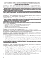
READ AND SAVE THESE INSTRUCTIONS BEFORE YOU START
INSTALLING THIS RANGEHOOD
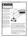
WARNING: - TO REDUCE THE RISK OF A RANGE TOP GREASE FIRE:
a) Never leave surface units unattended at high settings. Boilovers cause smoking and
greasy spillovers that may ignite. Heat oils slowly on low or medium setting.
b)AlwaysturnhoodONwhencookingathighheatorwhenambeingfood(i.e.Crepes
Suzette, Cherries Jubilee, Peppercorn Beef Flambé).
c) Clean ventilating fans frequently. Grease should not be allowed to accumulate on fan
orlter.
d) Use proper pan size. Always use cookware appropriate for the size of the surface element.
WARNING: - TO REDUCE THE RISK OF INJURY TO PERSONS IN THE EVENT OF A
RANGE TOP GREASE FIRE, OBSERVE THE FOLLOWING*:
a)SMOTHERFLAMESwithaclose-ttinglid,cookiesheet,ormetaltray,thenturnofftheburner.
BECAREFULTOPREVENTBURNS.IftheamesdonotgooutimmediatelyEVACUATE
AND CALL THE FIRE DEPARTMENT.
b) NEVER PICK UP A FLAMING PAN - You may be burned.
c) DO NOT USE WATER, including wet dishcloths or towels - a violent steam explosion will
result.
d) Use an extinguisher ONLY if:
1. You know you have a Class ABC extinguisher, and you already know how to operate it.
2. Thereissmallandcontainedintheareawhereitstarted.
3. Theredepartmentisbeingcalled.
4. Youcanghttherewithyourbacktoanexit.
* Based on "Kitchen Firesafety Tips" published by NFPA
WARNING - TO REDUCE THE RISK OF FIRE OR ELECTRIC SHOCK, do not use this
fan with any solid-state speed control device.
WARNING - TO REDUCE THE RISK OF FIRE, ELECTRICAL SHOCK, OR INJURY TO
PERSONS, OBSERVE THE FOLLOWING:
1. Use this unit only in the manner intended by the manufacturer. If you have any
questions, contact the manufacturer.
2. Before servicing or cleaning unit, switch power off at service panel and lock the
service disconnecting means to prevent power from being switched on acciden-
tally. When the service disconnecting means cannot be locked, securely fasten a
prominent warning device, such as a tag, to the service panel.
CAUTION: For General Ventilating Use Only. Do Not Use To Exhaust Hazardous or
Explosive Materials and Vapors.
WARNING - TO REDUCE THE RISK OF FIRE, ELECTRICAL SHOCK, OR INJURY TO
PERSONS, OBSERVE THE FOLLOWING:
1. InstallationWorkAndElectricalWiringMustBeDoneByQualiedPerson(s)InAccor-
dance With All Applicable Codes And Standards, Including Fire-Rated Construction.
2. Sufcientairisneededforpropercombustionandexhaustingofgasesthrough
theue(chimney)offuelburningequipmenttopreventbackdrafting.Followthe
heating equipment manufacturer's guideline and safety standards such as those
publishedbytheNational FireProtectionAssociation(NFPA), and the American
SocietyforHeating,RefrigerationandAirConditioningEngineers(ASHRAE),and
the local code authorities.

3
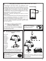
ALL WALL AND FLOOR OPENINGS WHERE THE RANGEHOOD IS INSTALLED MUST
BE SEALED.
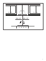
This rangehood requires at least 24" of clearance between the bottom of the rangehood
and the cooking surface or countertop. This hood has been approved by UL at this distance from
the cooktop.
This minimum clearance may be higher depending on local building codes. For gas cooktops and
combination ranges, a minimum of 30" is recommended and may be required.
Overhead cabinets on both sides of this unit must be a minimum of 18" above the cooking surface
or countertop. Consult the cooktop or range installation instructions given by the manufacturer
before making any cutouts.
MOBILE HOME INSTALLATION The installation of this rangehood must conform to the Manufactured
Home Construction and Safety Standards, Title 24 CFR, Part 3280 (formerly Federal Standard
for Mobile Home Construction and Safety, Title 24, HUD, Part 280). See Electrical Requirements.
• Venting system MUST terminate outside the home.
• DO NOT terminate the ductwork in an attic or other enclosed space.
• DO NOT use 4" laundry-type wall caps.
• Flexible-type ductwork is not recommended.
• DO NOT obstruct the ow of combustion and ventilation air.
• Failure to follow venting requirements may result in a re.
WARNING
!
VENTING REQUIREMENTS
Determine which venting method is best for your application. Ductwork can extend either through the
wall or the roof.
The length of the ductwork and the number of elbows should be kept to a minimum to provide efcient
performance. The size of the ductwork should be uniform. Do not install two elbows together. Use
duct tape to seal all joints in the ductwork system. Use caulking to seal exterior wall or oor opening
around the cap.
Flexible ductwork is not recommended. Flexible ductwork creates back pressure and air turbulence
that greatly reduces performance.
Make sure there is proper clearance within the wall or oor for exhaust duct before making cutouts.
Do not cut a joist or stud unless absolutely necessary. If a joist or stud must be cut, then a supporting
frame must be constructed.
WARNING - To Reduce The Risk Of Fire, Use Only Metal Ductwork.
CAUTION-Toreduceriskofreandtoproperlyexhaustair,besuretoductairoutside–Do
not vent exhaust air into spaces within walls or ceilings or into attics, crawl spaces, or garages.
3. When cutting or drilling into wall or ceiling, do not damage electrical wiring and
other hidden utilities.
4. Ducted fans must always be vented to the outdoors.
Cold Weather installations
An additional back draft damper should be installed to minimize backward cold air ow and a
nonmetallic thermal break should be installed to minimize conduction of outside temperatures as
part of the vent system. The damper should be on the cold air side of the thermal break. The break
should be as close as possible to where the vent system enters the heated portion of the house.

4
• Electrical ground is required on this rangehood.
• If cold water pipe is interrupted by plastic, nonmetallic gaskets or other materials, DO
NOT use for grounding.
• DO NOT ground to a gas pipe.
• DO NOT have a fuse in the neutral or grounding circuit. A fuse in the neutral or
grounding circuit could result in electrical shock.
• Check with a qualied electrician if you are in doubt as to whether the rangehood is
properly grounded.
• Failure to follow electrical requirements may result in a re.
WARNING
!
StateofCaliforniaProposition65Warning(USonly)
WARNING
This product contains chemicals known to the State of California to cause cancer and birth
defects or other reproductive harm.
For more information go to www.P65Warnings.ca.gov
ELECTRICAL REQUIREMENTS
A 120 volt, 60 Hz AC-only electrical supply is required on a separate 15 amp fused circuit. A time-delay
fuse or circuit breaker is recommended. The fuse must be sized per local codes in accordance with
the electrical rating of this unit as specied on the serial/rating plate located inside the unit near the eld
wiring compartment.

5
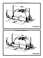
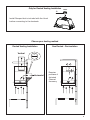
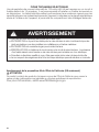
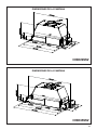
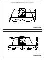
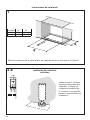
RANGEHOOD DIMENSIONS
RANGEHOOD DIMENSIONS
INSD29SSV
INSD35SSV
DRAFT 22-NOV-2018 13:20
DRAFT 22-NOV-2018 13:29

6
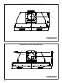
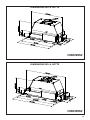
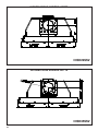
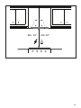
RANGEHOOD REAR INFORMATION
RANGEHOOD REAR INFORMATION
INSD29SSV
INSD35SSV
Palazzi, Walter
27-Nov-2019
Released
Palazzi, Walter
15-Nov-2019
Released

7
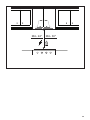
Min. 24" Min. 30"

8
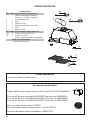
Available Accessories
Parts needed
- 6" Round Metal ductwork .
Direct Connect Wiring Box sku # WIREBOX
Liner 30" Stainless #LINE30ST (used only with INSD29SSV)
Liner 36" Stainless #LINE36ST (used only with INSD29SSV)
Liner 36" Stainless #LINE36PT (used only with INSD29SSV)
Activated Charcoal Filter sku #; FILTER1
Long Lasting Activated Charcoal Filter sku# FILTER1LL
Remote Control Accessory - REMCTRL2
Created by
-
Denomination
-
Lang EN
Sheet
1
/1
Modif.by
Approved by
Approval date
Doc. status
Drawing N.
NEW_DRAWING_BOX
Rev
01
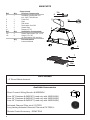
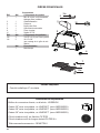
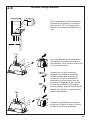
MAIN PARTS
Components
Ref. Qty. Product Components
1 1 Hood Body, complete with: Con-
trols, Light, Filters, Blower.
2 1 Power cord
6 2 Caps
7 4 Filter knobs
8 1 Recirculation Vent Grill
9 2 Greaselters
10 1 Damper ø 5 7/8"
Ref. Qty. Installation Components
12a 4 Greaseltersscrews5/32"x5/16"
12e 2 Screws1/8"x3/8"
(for Recirculation Grill mounting)
Qty. Documentation
1 Instruction Manual
H
I
H
I
H
I
H
I
6
1
9c
9c
5
8
7
5
4
4
6
9d
10
9e
1
9c
9c
5
8
7
5
4
4
6
9d
10
9e
7
9
1
9c
9c
5
8
7
5
4
4
6
9d
10
9e
12a

9
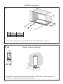
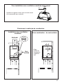
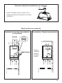
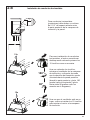
Choose your ducting method
Requires
purchase of
Activated
Charcoal
Accessory
Horizontal
Vertical
6"
H
I
Install Damper that is included with the Hood
before connecting to the ductwork.
Only for Ducted Venting Installation
Non Ducted - RecirculationDucted Venting Installation

10
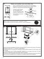
1
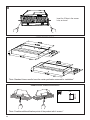
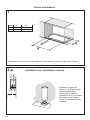
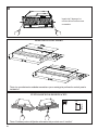
Cut out the opening in the underside of the cabinet as shown in Figure 1.
Installation Instructions
2.a
Install Roof or Wall Cap purchased separately. Connect the 6" metal ductwork to
the Roof or Wall Cap and then attach ductwork.
Ducted(infrontofVertical)
Hood 29" 35"
X 27 5/8" 33 3/4"
Y 13 9/16" 13 9/16"
0LQ
´
´
´
´
X
Y

11
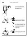
2.b
2 1/2”
>
For horizontal(rear) ducting there
must be a minimum of 2 1/2" of
space open between the back of the
Hood Insert and the wall.
For a horizontal ducting installation
the motor needs to be unsecured
by rst removing the 12 screws as
shown.
Once the screws are removed,
extract the blower from the body of
the Insert Hood and position it so the
transition opening is facing to the
rear wall (from the back remove and
rotate 180 degrees to the left, and
then ip it back 90 degrees as shown
in the diagram).
Once the blower is in place re-install
the 12 screws to fasten the motor to
the Insert Hood body.
Horizontal Ducting Installation
[
[

12
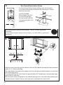
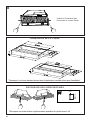
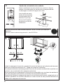
4
2x
2x
Install the Insert Hood through the cabinet cutout into the cabinet opening that has a minimum
height of 16 ". Allow for ducting.
The range hood is secured to the cabinet cutout by two spring loaded brackets, one on each
side of the range hood.
It is recommend that the Insert Hood is supported with a 3/4" wood base to insure proper align-
ment of the two side clips
After the Insert Hood is installed into the cabinet opening lock it into position by tightening the
indicated screws in each of the two side clips from underneath the Insert Hood.
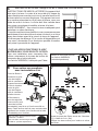
3
´
For Non-Ducted Recirculation venting route the ductwork
to a location above the hood where the discharge is vented
back into the room.
Non-Ducted Recirculation Option
Use the included
Recirculation Vent Grill
to cover the opening.
Secure the grill with the
2 screws provided in the
Install Kit.
Required Activated Charcoal Filter Accessory - sku # - FILTER1 (purchased
separately).
Long Lasting Activated Charcoal Filter Accessory - sku # FILTER1LL (purchased
separately).
Min. 24" Min. 30"

13
5
6 7
Attach each
charcoal
lter to the
black grid on
each side of
the blower.
Press the
charcoal
lter tightly
to the black
grid on the
blower side
and rotate
the lter
Before putting the lters, tighten the 2 knobs (7)
with 2 screws (12a). Use two hands to insert and
remove the lters.
Direct Connect Wiring Box
Accessory sku # WIREBOX
(purchased separately)
Created by
-
Denomination
-
Lang EN
Sheet
1
/1
Modif.by
Approved by
Approval date
Doc. status
Drawing N.
NEW_DRAWING_BOX
Rev
01
ELECTRICAL INSTALLATION WITH CONNECTION CABLE
ELECTRICAL INSTALLATION WITH
OPTIONAL WIRING BOX
For permanent wiring, use only the Direct Con-
nect Wiring Box accessory sku WIREBOX,
manufactured by Faber.
Max. 33 7/16”
For Non-Ducted Recirculation
Option
clockwise (towards the front of the insert hood)
until it locks into place. Turn counterclockwise
(towards the back of the insert hood) to remove.
1
2
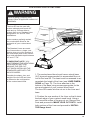
GROUNDING INSTRUCTIONS This appliance must
be grounded. In the event of an electrical short circuit,
grounding reduces the risk of electric shock by providing
an escape wire for the electric current. This appliance
is equipped with a cord having a grounding wire with a
grounding plug. The plug must be plugged into an outlet
that is properly installed and grounded.
WARNING - Improper grounding can result in a risk of
electric shock.
Consult a qualied electrician if the grounding instructions
are not completely understood, or if doubt exists as to
whether the appliance is properly grounded.
Do not use an extension cord. If the power supply cord
is too short, have a qualied electrician install an outlet
near the appliance.
Required Activated Charcoal Filter Accessory
- sku # - FILTER1
Long Lasting Activated Charcoal Filter
Accessory - sku # FILTER1LL
(purchased separately)
12a
7
9
12a
7

14
Standard Liner 36 Stainless (LINE36ST)
designed for 36” wide installations
Cadre Standard 36 Axier Inoxydable (620000305)
peut être employée les hottes encastrable sur mesure de 36"
Standard Liner 30 Stainless (LINE30ST)
designed for 30” wide installations
Cadre Standard 30 Axier Inoxydable (620000304)
peut être employée les hottes encastrable sur mesure de 30"
Note: Standard Liners are pre-cut for installation of Inca Smart. For installations with
the Inca HC SS, remove the additional perforated section.
Note: Les Cadres Standard sont précoupés pour l'installation de l'Inca Smart. Pour
des installations avec L'Inca HC SS, enlevez la section perforée additionnelle.
LINER DIMENSIONS / DIMENSIONS DU CADRE
FIGURE 1
Pre-Planning Your Installation -
Important: The recommended height to install this hood o the
cooktop is a minimum of 24" and a maximum of 30” for maximum eectiveness. Also consult the cooktop
manufacturer’s recommendation.
Planiez votre installation - Important : La hauteur recommandée pour installer cette hotte au-des-
sus de la surface de cuisson est d’un minimum de 24” et d’un maximum de 30” pour un maximum
d’ecacité. De plus, nous vous recommandons consulter le manuel de recommandations du fabricant
de la surface de cuisson.
MOD. INCA BIG ESB
RIF. -
N.DIS. 352_731.1
DATA 24-Nov-10
LINER DIMENSIONS
ADDITIONAL FIXATION POINTS
Standard Liner 36 Stainless (LINE36ST)
designed for 36” wide installations
Cadre Standard 36 Axier Inoxydable (620000305)
peut être employée les hottes encastrable sur mesure de 36"
Standard Liner 30 Stainless (LINE30ST)
designed for 30” wide installations
Cadre Standard 30 Axier Inoxydable (620000304)
peut être employée les hottes encastrable sur mesure de 30"
Note: Standard Liners are pre-cut for installation of Inca Smart. For installations with
the Inca HC SS, remove the additional perforated section.
Note: Les Cadres Standard sont précoupés pour l'installation de l'Inca Smart. Pour
des installations avec L'Inca HC SS, enlevez la section perforée additionnelle.
LINER DIMENSIONS / DIMENSIONS DU CADRE
FIGURE 1
Pre-Planning Your Installation -
Important: The recommended height to install this hood o the
cooktop is a minimum of 24" and a maximum of 30” for maximum eectiveness. Also consult the cooktop
manufacturer’s recommendation.
Planiez votre installation - Important : La hauteur recommandée pour installer cette hotte au-des-
sus de la surface de cuisson est d’un minimum de 24” et d’un maximum de 30” pour un maximum
d’ecacité. De plus, nous vous recommandons consulter le manuel de recommandations du fabricant
de la surface de cuisson.
MOD. INCA BIG ESB
RIF. -
N.DIS. 352_731.1
DATA 24-Nov-10
"Note: Standard Liners need to have the center perforation removed for installation"
"Note: Possible additional xation points of the product with 4 screws "
3/16 “
Min.1 3/8 “
Max.1
3/4 “
Insert the 2 Caps in the screws
hole, as shown.
8

15
FOR INSTALLATIONS WITH LINERS
CUSTOM/WOOD
HOOD
STANDARD LINER
WARNING
!
When building a custom hood,
always follow all applicable
codes and standards.
1. The custom/wood hood must have a sturdy base (3/4" plywood recommended) to
accomodate the cut-out for the Inca HC SS. The base must be recessed to accomodate
the height of the Liner (see LINER DIMENSIONS on Page 4). The Liner attaches to the
bottom of the base using screws appropriate for the size and material of your custom/
wood hood. The Inca HC SS inserts into the cut-out in the Liner and base.
2. Position the rear section of the Liner so that it abuts the back edge of your custom/
wood hood. Using a pen, trace the outline of the pre-cut out. Remove the Liner and
proceed to MAKE YOUR CUT-OUTS on Page 7. Install both sections of the Liner and
proceed to INSTALL THE Range hood on Page 7.
INCA HC SS
The Inca HC SS can be used with
custom cabinetry and hoods 30"
wide and up. Choose either a
custom liner or our Standard Liner
designed for 30" and 36" wide
installations.
Liners create a perfectly-sealed,
non-combustible finish for the
underside of your custom/wood
hood.
The Standard Liners are made up of
two sections: a larger, rear section
(pre-cut out for insertion of the
Inca Smart) and a front section for
a total adjustable depth between
16" and 17
7/8"
.
!!! IMPORTANT NOTE: YOU
MUST REMOVE THE ADDITIONAL
PERFORATED SECTION AROUND
THE PRE-CUT-OUT WHEN
INSTALLING THE STANDARD
LINER WITH THE INCA HC SS
MODEL.
Consider the shape, size, and
weight of the Inca HC SS and Liner
to determine the conguration
of the custom/wood hood. See
Range hood AND CUT-OUT
DIMENSIONS AND LINER
DIMENSIONS on Page 4.
FOR INSTALLATION WITH LINERS
When building a custom hood,
always follow all applicable codes and
standards.
WARNING
!
The Inca SD can be used with
custom cabinetry and hoods 30"
wide and up. Choose either a
custom liner or our Standard Liner
designed for 30" and 36" wide
installations.
Liners create a perfectly-sealed,
non-combustible nish for the
underside of your custom/wood
hood.
The Standard Liners are made
up of two sections: a larger, rear
section (pre-cut out for insertion of
the Inca Smart) and a front section
for a total adjustable depth between
16" and 17 7/8".
!!! IMPORTANT NOTE: YOU
MUST REMOVE THE ADDITIONAL
PERFORATED SECTION
AROUND THE PRE-CUT-
OUT WHEN INSTALLING THE
STANDARD LINER WITH THE
INCA SD MODEL.
Consider the shape, size, and
weight of the Inca SD and Liner
to determine the conguration
of the custom/wood hood.
1. The custom/wood hood must have a sturdy base
(3/4" plywood recommended) to accomodate the cut-
out for the Inca SD. The base must be recessed to ac-
comodate the height of the Liner (see LINER DIMEN-
SIONS on Page 13). The Liner attaches to the
bottom of the base using screws appropriate for the
size and material of your custom/ wood hood.
The Inca SD inserts into the cut-out in the Liner and
base.
2. Position the rear section of the Liner so that it abuts
the back edge of your custom/ wood hood. Using a
pen, trace the outline of the pre-cut out. Remove the
Liner and proceed to MAKE YOUR CUT-OUTS. Install
both sections of the Liner and proceed to INSTALL
THE Range hood.

16
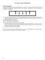
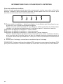
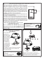
USE AND CARE INFORMATION
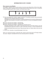
T1 T2 T3 T4 L
LT1 T2 T3 T4
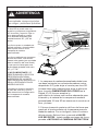
For Best Results
Start the rangehood several minutes before cooking to develop proper airow. Allow the
rangehood to operate for several minutes after cooking is complete to clear all smoke and
odors from the kitchen.
T1. Fan off button:turn the blower Off. The fan can be operated by pressing any of the fan setting buttons.
Hold down this button for 2 seconds to activate Delay off function which will keep the fan on for 15
minutes and automatically shut off.
T2. Fan settings buttons: Low speed.
T3. Fan settings buttons: Medium speed.
T4. Fan settings buttons: High speed / Intensive speed.
Hold down the button for 2 seconds to activate the intensive speed, which is timed to run for 6
minutes. At the end of this time it will automatically return to the speed set before.Suitable to deal
with maximum levels of cooking fumes.
L. Light button: On/Off switch for the lights.
NOTE: If your product has had a CFM adjustment, refer to the CFM adjustment manual for the infor-
mation. Some motor speeds or functions may be reduced.

17
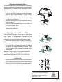
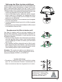
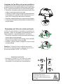
Cleaningmetalgreaselters
The metal grease lters can be cleaned in hot detergent
solution or washed in the dishwasher. They should be
cleaned every 2 months, or more frequently if use is
particularly heavy.
• Remove the lter, pushing the lever towards the back
of the unit and at the same time pulling downward.
• Wash the lter without bending it, leave it to dry
thoroughly before replacing (if the surface of the lter
changes color over time, this will have absolutely
no effect on its efciency).
• Replace, taking care to ensure that the handle
faces forward.
• Cleaning in dishwasher may dull the nish of
the metal grease lter.
• No water can be present in lters before in-
stalling back in hood.
Replacing Activated Charcoal Filter
The Activated Charcoal Filters are not washable
and cannot be regenerated, and should be
replaced approximately every 4 months of
operation, or more frequently with heavy usage.
• Remove the charcoal lter by rotating it clockwise (
backwards) until it unlocks from the motor housing and
pull off sideways.
• To re-insert each charcoal lter, place up against
the side of the blower and push it inward. Then
turn the charcoal lter clockwise (forward) until it
ts into place.
Caution: "When used in recirculation mode, to
Reduce the Risk of Fire and Shock use only
conversion kit Model FILTER 1 or FILTER1LL"
Lighting unit
• Replace the lamp with a new one of the same
type, making sure that you insert the two pins
properly into the housings on the lamp holder.
Gu10 self-ballasted led lamps
– listed in accordance with ul
1993/nmx-j-578/1-ance/csa
c22.2 No. 1993
a
b
a
b

18
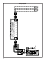
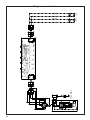
Wiring Diagram
991.0530.011 H90-503
D00004494_00
991.0530.011 H90-503
D00004494_00
120V 60Hz

19
January 4, 2016
FABER CONSUMER WARRANTY & SERVICE
All Faber products are warranted against any defect in materials or workmanship for the original purchaser
for a period of 1 year from the date of original purchase (requires proof of purchase). This warranty covers
labor and replacement parts. Faber, at its option, may repair or replace the product or components
necessary to restore the product to good working condition. To obtain warranty service, contact the dealer
from whom you purchased the range hood, or the local Faber distributor. If you cannot identify a local Faber
distributor, contact us at (508) 358-5353 for the name of a distributor in your area.
The following is not covered by Faber's warranty:
1. Service calls to correct the installation of your range hood, to instruct you how to use your range hood, to
replace or repair house fuses or to correct house wiring or plumbing.
2. Service calls to repair or replace range hood light bulbs, fuses or filters. Those consumable parts are
excluded from warranty coverage.
3. Repairs when your range hood is used for other than normal, single-family household use.
4. Damage resulting from accident, alteration, misuse, abuse, fire, flood, acts of God, improper installation,
installation not in accordance with electrical or plumbing codes or Faber documentation, or use of products
not approved by Faber.
5. Replacement parts or repair labor costs for units operated outside the United States or Canada, including
any non-UL or C-UL approved Faber range hoods.
6. Repairs to the hood resulting from unauthorized modifications made to the range hood.
7. Expenses for travel and transportation for product service in remote locations and pickup and delivery
charges. Faber range hoods should be serviced in the home.
THIS WARRANTY DOES NOT ALLOW RECOVERY OF INCIDENTAL OR CONSEQUENTIAL DAMAGES, INCLUDING, WITHOUT
LIMITATION, DIRECT, INDIRECT, INCIDENTAL, SPECIAL OR CONSEQUENTIAL DAMAGES, PERSONAL INJURY/WRONGFUL
DEATH OR LOST PROFITS FABER WARRANTY IS LIMITED TO THE ABOVE CONDITIONS AND TO THE WARRANTY PERIOD
SPECIFIED HEREIN AND IS EXCLUSIVE. EXCEPT AS EXPRESSLY SPECIFIED IN THIS AGREEMENT, FABER DISCLAIMS ALL
EXPRESS OR IMPLIED CONDITIONS, REPRESENTATIONS, AND WARRANTIES INCLUDING, WITHOUT LIMITATION, ANY
IMPLIED WARRANTIES OF MERCHANTABILITY OR FITNESS FOR A PARTICULAR PURPOSE
.
This warranty gives you specific legal rights that may vary from state to state.
Model#: ______________________________ Serial #: _____________________________

20
VEUILLEZ LIRE ET CONSERVER LA PRÉSENTE NOTICE AVANT DE
COMMENCER L'INSTALLATION DE LA HOTTE DE CUISINE
AVERTISSEMENT:-POUR RÉDUIRE LE RISQUE D'UN FEU DE GRAISSE SUR LA TABLE DE
CUISSON:
a) Ne laissez jamais sans surveillance les éléments de la surface de cuisson à température élevée.
Les bouillonnements excessifs peuvent provoquer de la fumée et les débordements de graisse
peuvents'enammer.L'huiledoitêtrechaufféelentement,àunetempératurebasseoumoyenne.
b) Assurez-vous de toujours mettre en marche le ventilateur de la hotte lorsque vous cuisinez
àtempératureélevéeoupréparezunmetsambé(p.ex.crêpesSuzette,cerisesjubilé,bœuf
ambé).
c) Nettoyez régulièrement les ventilateurs d'aspiration. Assurez-vous de ne pas laisser de la graisse
s'accumulersurleventilateurouleltre.
d)Utiliseztoujoursdespoêlesetcasserolesdelatailleappropriée.Utiliseztoujoursdesustensiles
de cuisine de la taille adaptée à celle de l'élément chauffant.
AVERTISSEMENT:-POURPRÉVENIRLESBLESSURESENCASDEFEUDEGRAISSESURLA
TABLEDECUISSON,SUIVEZLESRECOMMANDATIONSSUIVANTES*:
a) ÉTOUFFEZ LES FLAMMES à l'aide d'un couvercle hermétique, d'une plaque à biscuits ou d'un
plateau métallique, puis éteignez le brûleur. FAITES ATTENTION AUX BRÛLURES. Si le feu ne
s'éteint pas immédiatement, QUITTEZ LES LIEUX ET APPELEZ LES POMPIERS.
b) NE PRENEZ JAMAIS UNE CASSEROLE EN FLAMME - Vous pourriez vous brûler.
c) N'UTILISEZ JAMAIS DE L'EAU, ni un linge à vaisselle ou un torchon mouillé, pour éteindre le feu.
Cela pourrait provoquer une violente explosion de vapeur.
d)UtilisezunextincteurUNIQUEMENTsi:
1. Vousêtescertainqu'ils'agitd'unextincteurdeclasseABCetquevousconnaissezbienson
mode d'emploi.
2. Le feu est de faible intensité et se limite à l'endroit où il a démarré.
3. Les pompiers ont déjà été appelés.
4. Unevoiedesortiesetrouvederrièrevouspendantquevouséteignezlesammes
* D'après le guide «Kitchen Firesafety Tips» publié par la NFPA aux États-Unis
AVERTISSEMENT - POUR RÉDUIRE LE RISQUE D'INCENDIE OU DE CHOC ÉLECTRIQUE, n'utilisez
jamais ce ventilateur en association avec un dispositif de réglage de vitesse à semi-conducteurs.
AVERTISSEMENT - POUR RÉDUIRE LES RISQUES D'INCENDIE, DE CHOC ÉLECTRIQUE OU DE
BLESSURECORPORELLE,RESPECTEZLESINSTRUCTIONSSUIVANTES:
1. Utilisez cet appareil uniquement de la façon prévue par le fabricant. Pour toute question, com-
muniquez avec le fabricant.
2. Avant de procéder à l'entretien ou au nettoyage de l'appareil, coupez l'alimentation au niveau du
panneau électrique et verrouillez-le pour vous assurer que l'électricité n'est pas rétablie accidentel-
lement.S'iln'estpaspossibledeverrouillerledispositifd'interruptiondel'alimentation,afchezde
façon ferme et bien visible un avis de danger, par exemple à l'aide d'une étiquette sur le panneau.
ATTENTION:Destinéàunusagedeventilationgénéraleuniquement.N'utilisezpascedispositif
pour l'aspiration de vapeurs ou de matériaux dangereux ou explosifs.
AVERTISSEMENT - POUR RÉDUIRE LES RISQUES D'INCENDIE, DE CHOC ÉLECTRIQUE OU DE
BLESSURECORPORELLE,RESPECTEZLESINSTRUCTIONSSUIVANTES:
1. L'installationetlebranchement électriquedoiventêtreréalisésparun technicienqualiéet
conformément à tous les codes et normes en vigueur, incluant ceux concernant la construction
à l'épreuve du feu.
2. Andegarantirunecombustionetuneévacuationadéquatesdesgazparlesconduitesdela
cheminée des appareils à combustion, une bonne aération est nécessaire pour éviter le refou-
lement. Respectez les lignes directrices fournies par le fabricant du matériel chauffant, ainsi que
lesnormesdesécuritécommecellespubliéesparlaNationalFireProtectionAssociation(NFPA)
etlaAmericanSocietyforHeating,RefrigerationandAirConditioningEngineers(ASHRAE)aux
États-Unis, ainsi que les codes en vigueur dans votre région.
La page est en cours de chargement...
La page est en cours de chargement...
La page est en cours de chargement...
La page est en cours de chargement...
La page est en cours de chargement...
La page est en cours de chargement...
La page est en cours de chargement...
La page est en cours de chargement...
La page est en cours de chargement...
La page est en cours de chargement...
La page est en cours de chargement...
La page est en cours de chargement...
La page est en cours de chargement...
La page est en cours de chargement...
La page est en cours de chargement...
La page est en cours de chargement...
La page est en cours de chargement...
La page est en cours de chargement...
La page est en cours de chargement...
La page est en cours de chargement...
La page est en cours de chargement...
La page est en cours de chargement...
La page est en cours de chargement...
La page est en cours de chargement...
La page est en cours de chargement...
La page est en cours de chargement...
La page est en cours de chargement...
La page est en cours de chargement...
La page est en cours de chargement...
La page est en cours de chargement...
La page est en cours de chargement...
La page est en cours de chargement...
La page est en cours de chargement...
La page est en cours de chargement...
La page est en cours de chargement...
La page est en cours de chargement...
-
 1
1
-
 2
2
-
 3
3
-
 4
4
-
 5
5
-
 6
6
-
 7
7
-
 8
8
-
 9
9
-
 10
10
-
 11
11
-
 12
12
-
 13
13
-
 14
14
-
 15
15
-
 16
16
-
 17
17
-
 18
18
-
 19
19
-
 20
20
-
 21
21
-
 22
22
-
 23
23
-
 24
24
-
 25
25
-
 26
26
-
 27
27
-
 28
28
-
 29
29
-
 30
30
-
 31
31
-
 32
32
-
 33
33
-
 34
34
-
 35
35
-
 36
36
-
 37
37
-
 38
38
-
 39
39
-
 40
40
-
 41
41
-
 42
42
-
 43
43
-
 44
44
-
 45
45
-
 46
46
-
 47
47
-
 48
48
-
 49
49
-
 50
50
-
 51
51
-
 52
52
-
 53
53
-
 54
54
-
 55
55
-
 56
56


Faber Inca SD 29 SS Guide d'installation
- Catégorie
- Hottes
- Taper
- Guide d'installation
- Ce manuel convient également à
dans d''autres langues
Documents connexes
-
Faber INHC29SSV Guide d'installation
-
-
-
-
-
-
-
-
-

