Simplicity SMI PREMIUM RIDER CORONET, 15,5/17,5 CE FR Manuel utilisateur
- Catégorie
- Tondeuses à gazon
- Taper
- Manuel utilisateur
Ce manuel convient également à

Part No. 885390
Revision -
Original Instructions
Mfg. No. Description
7800675 Simplicity Coronet RD Rider 15,5HP (FR)
7800679 Simplicity Coronet RD Rider 17,5HP (FR)
Premium Rider (CE)
Operator’s Manual
Not for
Reproduction

2
Not for
Reproduction

3/8
7
4
3
5
1
2
8
6
3
1
3
4
2
Not for
Reproduction

4
2
1
5
7
6
1
2
3
8
Not for
Reproduction

5
10
11
12
9
Not for
Reproduction

6
2
1
15 16
A
B
13 14
Not for
Reproduction

7
17 18
2019
Not for
Reproduction

8
4
2
1
3
2
23
24
2
1
4
3
21
4
1
3
2
22
Not for
Reproduction

9
en
Illustrations . . . . . . . . . . . . . . . . . . . . . . . . . . . . . . . . . . . . . . . . . . . . . . 3
Table of Contents . . . . . . . . . . . . . . . . . . . . . . . . . . . . . . . . . . . . . . . . . 9
Operator Safety . . . . . . . . . . . . . . . . . . . . . . . . . . . . . . . . . . . . . . . . . . 10
Assembly . . . . . . . . . . . . . . . . . . . . . . . . . . . . . . . . . . . . . . . . . . . . . . . 14
Features and Controls . . . . . . . . . . . . . . . . . . . . . . . . . . . . . . . . . . . . 17
Operation . . . . . . . . . . . . . . . . . . . . . . . . . . . . . . . . . . . . . . . . . . . . . . . 18
Maintenance . . . . . . . . . . . . . . . . . . . . . . . . . . . . . . . . . . . . . . . . . . . . 23
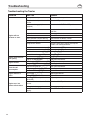
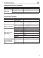
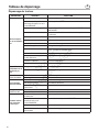
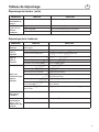
Troubleshooting Chart . . . . . . . . . . . . . . . . . . . . . . . . . . . . . . . . . . . . 26
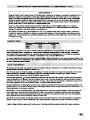
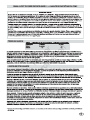
Warranty. . . . . . . . . . . . . . . . . . . . . . . . . . . . . . . . . . . . . . . . . . . . . . . . 28
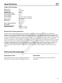
Specifications . . . . . . . . . . . . . . . . . . . . . . . . . . . . . . . . . . . . . . . . . . . 29
Parts and Accessories . . . . . . . . . . . . . . . . . . . . . . . . . . . . . . . . . . . . 29
Table of Contents
Not for
Reproduction

10
en
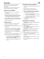
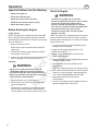
6. All drivers should seek and obtain professional and
practical instruction. Such instruction
should emphasize:
a. the need for care and concentration when
working with ride-on machines;
b. control of a ride-on machine sliding on a slope
will not be regained by the application of the
brake. The main reasons for loss of control are:
• insufficient wheel grip;
• being driven too fast;
• inadequate braking;
• the type of machine is unsuitable for
its task;
• lack of awareness of the effect of
ground conditions, especially slopes;
• incorrect hitching and
load distribution.
Preparation
1. While mowing, always wear substantial footwear
and long trousers. Do not operate the equipment
when barefoot or wearing open sandals.
2. Thoroughly inspect the area where the equipment
will be used and remove all objects which may be
thrown by the machine.
3. WARNING-Fuel is highly flammable.
a. Store fuel in containers specifically
designed for this purpose.
b. Refuel outdoors only and do not smoke
while refuelling.
c. Add fuel before starting the engine. Never
remove the cap of the fuel tank or add fuel
while the engine is running or when the engine
is hot.
d. If fuel is spilled, do not attempt to start the
engine but move the machine away from the
area of spillage and avoid creating any source
of ignition until the fuel vapors have dissipated.
e. Replace all fuel tanks and container
caps securely.
4. Replace faulty silencers.
5. Before using, always visually inspect to see that
the blades, blade bolts, and cutter assembly are
not worn or damaged. Replace worn or damaged
blades and bolts in sets to preserve balance.
6. On multi-blade machines, take care as rotating one
blade can cause other blades to rotate.
KNOW YOUR PRODUCT
If you understand the unit and how the unit operates, you
will get the best performance. As you read this manual,
compare the illustrations to the unit. Learn the location
and the function of the controls. To help prevent an
accident, follow the operating instructions and the safety
rules. Save these original instructions for future reference.
It is the responsibility of the owner to follow the
instructions contained in this manual.
FOR RIDE-ON (RIDING) ROTARY
MOWER MACHINES
Training
1. Read the instructions carefully. Be familiar with the
controls and the proper use of the equipment.
2. Never allow children or people unfamiliar with these
instructions to use the mower. Local regulations
may restrict the age of the operator.
3. Never mow while people, especially children, or
pets are nearby.
4. Keep in mind that the operator or user is
responsible for accidents or hazards occurring to
other people or their property.
5. Do not carry passengers.
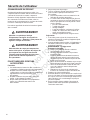
Operator Safety
WARNING
Look for this symbol to indicate important
safety precautions. This symbol indicates:
“Attention! Be Alert! Your Safety Is At Risk.”
WARNING
This cutting machine is capable of amputating
hands and feet and throwing objects. Failure to
observe the following safety instructions could
result in serious injury or death to the operator
or bystanders.
Not for
Reproduction

11
en
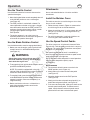
Operator Safety
Operation
1. Do not operate the engine in a confined space
where dangerous carbon monoxide fumes
can collect.
2. Mow only in daylight or in good artificial light.
3. Before attempting to start the engine, disengage all
blade attachment clutches and shift into neutral.
4. Do not use on slopes of more than 10 degrees.
5. Remember there is no such thing as a “safe” slope.
Travel on grass slopes requires particular care. To
guard against overturning:
a. do not stop or start suddenly when going up
or downhill;
b. engage clutch slowly, always keep machine in
gear, especially when travelling downhill;
c. machine speeds should be kept low on slopes
and during tight turns;
d. stay alert for humps and hollows and other
hidden hazards;
e. never mow across the face of the slope, unless
the mower is designed for this purpose.
6. Use care when pulling loads or using
heavy equipment.
a. Use only approved drawbar hitch points.
b. Limit loads to those you can safely control.
c. Do not turn sharply. Use care when driving
in reverse.
d. Use counterweight(s) or wheel weights when
suggested in the Operator’s Manual.
7. Watch out for traffic when crossing or
near roadways.
8. Stop the blades rotating before crossing surfaces
other than grass.
9. When using any attachments, never direct the
discharge of material toward bystanders nor allow
anyone near the machine while in operation.
10. Never operate the mower with defective guards or
shields, or without safety protective devices
in place.
11. Do not change the engine governor settings or
overspeed the engine. Operating an engine at
excessive speed may increase the hazard of
personal injury.
12. Before leaving the operator’s position
a. disengage the power take-off and lower
the attachments;
b. change into neutral and set the parking brake;
c. stop the engine and remove the key.
13. Disengage drive to attachments, stop the engine,
and disconnect the spark plug wire(s) or remove
the ignition key
a. before cleaning blockages or
unclogging chute;
b. before checking, cleaning, or working on
the mower;
c. after striking a foreign object. Inspect the
mower for damage and make repairs before
restarting and operating the equipment;
d. if the machine starts to vibrate abnormally
(check immediately).
14. Disengage drive to attachments when transporting
or not in use.
15. Stop the engine and disengage drive to
the attachment
a. before refuelling;
b. before removing the grass bagger;
c. before making height adjustment unless
adjustment can be made from the operator’s
position.
16. Reduce the throttle setting during engine run-out
and, if the engine is provided with a shut-off valve,
turn the fuel off at the conclusion of mowing.
17. Before and when backing, look behind and down
for small children.
18. Use extra care when approaching blind corners,
shrubs, trees or other objects that may
obscure vision.
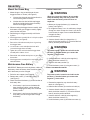
Maintenance and Storage
1. On multi-blade machines, take care as rotating one
blade can cause other blades to rotate.
2. When machine will be parked, stored or left
unattended, lower the cutting means unless a
positive mechanical lock is used.
3. Keep all nuts, bolts, and screws tight to be sure the
equipment is in safe working condition.
4. Never store the equipment with fuel in the tank
inside a building where fumes may reach an open
flame or spark.
5. Allow the engine to cool before storing in
any enclosure.
6. To reduce the fire hazard, keep the engine, silencer,
battery compartment and fuel storage area free of
grass, leaves, or excessive grease.
7. Check the grass bagger frequently for wear
or deterioration.
8. Replace worn or damaged parts for safety.
9. If the fuel tank has to be drained, this should be
done outdoors.
Not for
Reproduction

12
en
Operator Safety
(
)
20LB
(
)
34
LB
_
_
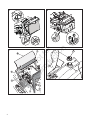
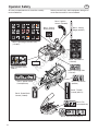
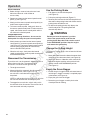
All safety and operation decals should be carefully
read and followed.
Decal - Operating Instructions (CE)
(1734027)
Decal - Parking
Brake (724281)
Decal - Ignition
Switch (1722806)
Decal - Cutting
Height (885253)
Decal - Roll Release
(1723425)
Decal - Hot Surface
(885216)
Decal - Throttle
Control (885171)
Decal - Discharge Tube
(1721107)
Decal - Fire
Hazard (885218)
Decal - Brake/Clutch
Control (729695)
Decal - Speed Control
Pedal (885169)
Decal - Draw Bar Load
(729677)
ID Tag
Decal - Sever Hazard (885217)
Serious personal injury and/or equipment damage can
result when these decals are not followed.
Not for
Reproduction

13
en
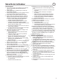
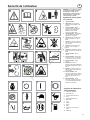
Operator Safety
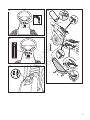
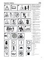
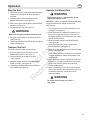
IMPORTANT: The following
symbols are located on your unit
or on literature supplied with the
product. Before you operate the
unit, learn and understand the
purpose for each symbol.
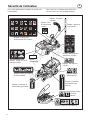
Safety Warning Symbols
1 WARNING.
2 IMPORTANT: Read Owner’s
Manual Before Operating This
Machine.
3 WARNING: Thrown Objects.
Keep Bystanders Away. Read
User Instructions Before
Operating This Machine.
4 WARNING: Do Not Use This
Machine On Slopes Greater
Than 10 Degrees.
5 DANGER: Keep People,
Especially Children, Away
From Unit.
6 DANGER: Stay Clear Of Mower
Blade As Long As Engine Is
Running.
7 DANGER: Keep Feet And
Hands Away From Rotating
Blade.
8 DANGER: Disconnect Spark
Plug Wire Before Servicing
Unit.
9 WARNING: Hot Surface.
10 WARNING: Use Caution When
Connecting Or Disconnecting
Accessories.
11 WARNING: Crushed Fingers.
12 IMPORTANT: Follow
Instructions In Owner’s Manual
To Level The Deck.
13 DANGER: Stay Clear Of Mower
Blade As Long As Engine Is
Running.
14 WARNING: Discharge Tube. Do
not operate as a bagger unless
discharge chute is in place.
15 WARNING: Fire Hazard. Yard
debris is combustible. Keep
unit cleaned of debris.
Control and Operating
Symbols
1 Engine Start
2 Engine Stop
3 Engine Run
4 Brake
5 Parking Brake
6 Clutch
7 Slow
8 Fast
9 Choke
10 Oil
11 Blade Rotation Control
12 Fuel
1
2
3
4
5
6
7
8
9
10
11
12
Not for
Reproduction

14
en
Assembly
NOTE: All fasteners are in the parts bag. Do not
discard any parts or material until the unit
is assembled.
Before doing any assembly or maintenance to the
mower, remove the wire from the spark plug.
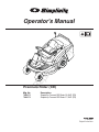
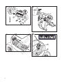
Install the Front Wheels
1. Make sure the valve stem (1) is to the outside
(see Figure 1).
2. Slide the front wheel (2) onto the spindle (3).
3. Secure the front wheel (2) with washers (4 and 5),
and cotter pin (6) Bend the ends of the cotter pin
apart to keep the front wheel on the spindle.
4. If your model has hub caps (7), install the hubcaps.
Make sure the washers hold the hubcaps in place.
5. Repeat for opposite side.
Install the Seat
1. Carefully remove the plastic bag from the seat.
2. Raise the seat support (1) (see Figure 2).
3. Align the holes in the seat (2) to the slots in the
seat support.
4. Install the seat (2) to the seat support (1) and
adjustment lever (3) with washers (4) and bolts (5).
NOTE: Install the washers on the left side only.
5. Connect the wiring harness (6) to the seat switch
(7) under the seat.
6. Lower the seat to the normal operating position.
7. Check the operation of the seat adjustment.
a. If the seat needs adjustment, raise the
adjustment lever (3) toward the seat and move
the seat to the desired position.
b. Release the adjustment lever to lock the seat
in place.
Assemble the Steering Wheel
1. Make sure the front wheels point forward as shown
in Figure 3.
2. Slide the bellows (1) over the console.
3. Slide the steering post (2) into the console.
4. Attach the steering wheel (3) to the steering post
(2) with screw (4) and washer (5). Tighten screw
but be careful not to over-tighten.
a. Push on the steering wheel. The steering post
will lock onto the pinion gear (6).
b. Pull on the steering wheel. Make sure that the
steering post is locked in place.
5. Install the plate (7) and cover (8) to the
steering wheel.
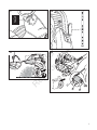
Assemble the Grass Bag
1. Slide the bottom tube (1) onto the bagger frame (2)
(see Figure 4).
2. Align the holes in bottom tube with hole in the
bagger frame.
3. Install the cotter pins (3) into holes and bend the
ends to secure to the frame.
4. Slide the frame assembly onto the grass bag (4).
5. Attach the bag clips to the frame assembly.
6. Align the bagger cover (5) to holes in frame.
7. Use screws (6) and (7) to assemble the side and
top of the cover to the bagger frame.
8. Assemble the bagger handle (8) thru hole in cover
and frame.
9. Secure the bagger handle with washer (9), screw
(10), and nut (11).
10. Install rear bagger handle (12) to cover using two
screws (13).
Not for
Reproduction

15
en
Assembly
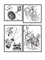
Mount the Grass Bag
1. Mount the grass bag assembly onto the rear
bagger brackets as shown (see Figure 5).
a. Use one hand to grab onto the handle at the
rear of the bag frame assembly.
b. Use the other hand to hold the top bagger
handle and guide the bag frame assembly
onto the rear bagger brackets.
2. When mounting the bagger frame assembly, hold
the bottom of the grass bagger assembly slightly
away from the rear plate.
3. Rotate the grass bagger assembly until it locks
in place.
4. If the bagger frame assembly fails to lock in place, adjust
the two latches (see Figure 6).
5. Remove the side and bottom trim pieces of grass bag
from bagger frame.
6. Loosen the two screws and adjust the latch until it
contacts the bagger frame assembly.
7. Tighten the screws and check that the bagger frame
assembly will lock when closed.
8. Reinstall the side and bottom trim pieces of grass bag to
bottom tube.
9. If the bagger frame assembly will not stay locked, see an
authorized dealer.
Maintenance Free Battery
IMPORTANT: Before you attach the battery cables to
the battery, check the battery date. The battery date
tells if the battery must be charged.
1. Raise the seat support (see Figure 2).
2. Remove two screws (1) and battery cover (2)
(see Figure 7).
3. Check the side of the battery (3) for the location of
the battery date.
a. If the battery is put into service before this
date, the battery cables can be attached
without charging the battery. See “Install the
Battery Cables.”
b. If the battery is put into service after this date,
the battery must be charged. See “Charge
the Battery.”
CHARGE THE BATTERY
1. Before you charge the battery (3), remove the
battery (see Figure 7).
2. To charge the battery, use a 12 volt battery charger.
Charge at a rate of 6 amps for 1 hour. If you do not
have a battery charger, have an authorized dealer
charge the battery.
3. Install the battery.
4. Connect the red cable (6) to the positive (+)
terminal using the fasteners (7). Place the terminal
boot (5) onto the positive terminal.
5. Connect the black cable (8) to the negative (-)
terminal with the fasteners (7).
6. Connect the battery retainer (4).
7. Install the battery cover (2) using two screws (1).
INSTALL THE BATTERY CABLES
1. Remove the protective caps from the battery
terminals (see Figure 7).
2. Slide the terminal boot (5) onto the red cable (6).
3. Connect the red cable (6) to the positive (+)
terminal with the fasteners (7). Place the terminal
boot (5) onto the positive terminal.
4. Connect the black cable (8) to the negative (-)
terminal with the fasteners (7).
5. Install the battery cover (2) with the two screws (1).
WARNING
When you charge the battery, do not smoke.
Keep the battery away from any sparks. The
fumes from the battery acid can cause an
explosion.
WARNING
To prevent sparks, fasten the red cable to the
positive (+) terminal before you connect the
negative (-) black cable.
WARNING
To prevent sparks, fasten the red cable to the
positive (+) terminal before you connect the
negative (-) black cable.
Not for
Reproduction

16
en
Assembly
WARNING
Follow the engine manufacturer’s instructions
for the type of fuel and oil to use. Always use a
safety fuel container. Do not smoke when
adding fuel to the engine. When inside an
enclosure, do not fill with fuel. Before you add
fuel, stop the engine. Let the engine cool for
several minutes.
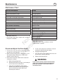
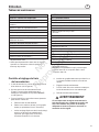
Check the Tires
Check the air pressure in the tires. Tires with too much
air pressure will cause the unit to ride rough. Also, the
wrong air pressure will keep the mower deck from
cutting level. The correct air pressure is: Front Tires 1,0
BAR (14 PSI), Rear Tires 0,7 BAR (10 PSI). The tires
were over inflated for shipment.
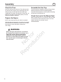
Prepare the Engine
NOTE: Check the level of the oil. Add oil as needed.
See the engine manufacturer’s instructions for the type
of fuel and oil to use. Before you use the unit, read the
information on safety, operation, maintenance,
and storage.
Assemble the Fuel Cap
The fuel cap will be shipped in the Parts Bag and tape
will be placed over the fuel tank opening during
shipment. Before operation, remove tape from opening
on fuel tank and install fuel cap.
Check the Level of the Mower Deck
Make sure the level of cut is still correct. After you mow
a short distance, look at the area that was cut. If the
mower deck does not cut level, see an
authorized dealer.
Not for
Reproduction

17
en
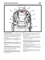
Features and Controls
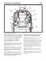
LOCATION OF CONTROLS
Throttle Control Lever (1): Use the throttle control
lever to increase or decrease engine speed. Move the
throttle up to increase engine speed and down to
decrease engine speed. Always operate at
FULL throttle.
Clutch/Brake Pedal (2): The pedal has two functions.
The first function is a clutch. The second function is
abrake.
Ignition Switch (3): Use the ignition switch to start
and stop the engine. Never leave the ignition switch in
the RUN position with the engine stopped. This drains
the battery.
Parking Brake Knob (4): The parking brake knob is
used to lock the parking brake when the tractor is
stopped. Fully depress the brake pedal and pull up on
the knob to engage the parking brake.
Forward Speed Control Pedal (5): The tractor’s
forward ground speed is controlled by the forward
speed control pedal. Depress the pedal to increase
forward ground speed.
Reverse Speed Control Pedal (6): Use the reverse
ground speed pedal to control the reverse ground
speed of the tractor.
Lift Lever (7): The lift lever controls the mower cutting
height. There are six cutting height levels available (1 -
Lowest Cut, 6 - Highest Cut).
Blade Rotation Control (8): Use the blade rotation
control to start and stop the rotation of the blade. Pull
up on the switch to engage the blade rotation control
and push down to disengage.
Fuel Tank (9): To add fuel, remove the filler cap. Be
sure to leave room for heat expansion.
Grass Bagger Handle (10): The grass bagger handle
opens the bagger so that it can be emptied and closed
for mowing.
Seat Adjustment Lever (11): Pull up on the lever to
adjust the location of the seat. Release lever to lock
seat in place.
1
2
3
5
6
7
8
10
9
11
4
Not for
Reproduction

18
en
Operation
Start the Engine
NOTE: The engine was shipped from the factory filled
with oil. Check the level of the oil. Add oil as needed.
See the engine manufacturer’s instructions for the type
of fuel and oil to use.
1. Push the clutch/brake pedal completely forward.
Keep your foot on the pedal.
2. Make sure the speed control pedal is in the
NEUTRAL position.
3. Make sure the blade rotation control is in the
DISENGAGE position.
4. Move the throttle control completely forward to the
CHOKE or FAST position.
5. Turn the ignition key to the START position
(see Figure 9).
NOTE: If the engine does not start after four or five
tries, move the throttle control to the FAST position.
Again try to start the engine. If the engine will not
start, see the TROUBLESHOOTING CHART.
6. Slowly move the throttle control to the
SLOW position.
7. To start a hot engine, move the throttle control to a
position between FAST and SLOW.
Before Starting the Engine
CHECK THE OIL
NOTE: The engine was shipped from the factory filled
with oil. Check the level of the oil. Add oil as needed.
See the engine manufacturer’s instructions for the type
of fuel and oil to use.
1. Make sure the unit is level.
NOTE: Do not check the level of the oil while the
engine runs.
2. Check the oil. Follow the procedure in the engine
manufacturer’s instructions.
3. If necessary, add oil until the oil reaches the FULL
mark on the dipstick. Do not add too much oil.
ADD FUEL
1. Remove the filler cap (1) (see Figure 8).
2. Fill the fuel tank (2) to the FULL (3) position with
regular unleaded fuel.
NOTE: Do not use premium unleaded fuel. Make
sure the fuel is fresh and clean. Leaded fuel will
increase deposits and shorten the life of the valves.
WARNING
Always use a safety fuel container. Do not
smoke when adding fuel to the fuel tank. Do
not add fuel when you are inside an enclosure.
Before you add fuel, stop the engine and let the
engine cool for several minutes.
WARNING
The electrical system has an operator
presence system that includes a sensor switch
for the seat. These components tell the
electrical system if the operator is sitting on
the seat. This system will stop the engine when
the operator leaves the seat. For your
protection, always make sure this system
operates correctly.
Important! Before You Start Mowing
• Check the engine oil.
• Fill the fuel tank with fuel.
• Check the air pressure of the tires.
• Check the level of the mower housing.
• Attach the battery cables.
Not for
Reproduction

19
en
Operation
Use the Throttle Control
Use the throttle control to increase or decrease the
speed of the engine.
1. Move the throttle/choke control completely forward
to the CHOKE position to start a cold engine
(see Figure 10).
2. The FAST position is marked with a detent. For
normal operation and when using a grass bagger,
move the throttle control to the FAST position. For
maximum charging of the battery and for a cooler
running engine, operate the engine in the
FAST position.
3. The engine governor is set at the factory for
maximum performance. Do not adjust the governor
to increase the speed of the engine.
Use the Blade Rotation Control
Use the blade rotation control to engage the blade(s).
1. Before you start the engine, make sure the blade
rotation control is in the DISENGAGE position
(see Figure 11).
2. To engage the blade, pull the blade rotation control
upward to the ENGAGE position.
NOTE: This model is equipped with a bag full
indicator. With the blade rotation control engaged, a
buzzer will sound when the bag is full.
3. To stop the blade, move the blade rotation control
to the DISENGAGE position. Before you leave the
operator’s position, make sure the blade(s) has
stopped rotating.
4. Before you ride the unit across a sidewalk or a
road, move the blade rotation control to the
DISENGAGE position.
WARNING
Always keep your hands and feet away from
the blade, deflector opening, and the mower
deck when the engine runs.
Attachments
See an authorized dealer for a list of the available
attachments.
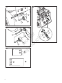
Install the Mulcher Cover
The mulcher cover lets you mulch the grass for a clean,
fine cut. Install as follows.
1. Follow the steps shown in Figure 12 to remove the
rear discharge chute and chute extension.
2. Mount the mulcher cover (1) to the mower deck with
the bolts (4), washers (2), and flange locknuts (3)
(see Figure 13).
3. For mulching operation, install mulch blade as an
accessory part. See authorized dealer.
Use the Speed Control Pedals
The drive system uses a Hydrostatic Automatic Drive
Transmission. The hydrostatic transmission is very easy
to operate. This type of drive system does not require a
shift lever or a clutch pedal.
The speed and direction of travel is controlled by a
forward speed control pedal and reverse speed control
pedal operated with your right foot.
NOTE: Do not use the brake pedal in normal operation.
Only use the brake pedal to quickly stop in
an emergency.
DRIVE FORWARD
1. The automatic drive disconnect must be in the
DRIVE position (see A, Figure 14).
2. Slowly release your foot from the brake pedal
(see Figure 15).
3. Move the throttle control to the FAST position
(see Figure 10).
4. Slowly push the forward speed control pedal (1) to
enable forward ground speed (see Figure 16).
5. To increase forward speed, slowly push down on the
forward speed control pedal. To reduce forward
speed, slowly release the forward speed control
pedal until the unit slows to the desired speed.
Not for
Reproduction

20
en
Operation
DRIVE IN REVERSE
1. Before driving in reverse, look to the rear. Look
behind and down for small children to
ensure safety.
2. Remove your foot from the forward speed control
pedal (1) (see Figure 16).
3. Slowly push the reverse speed control pedal (2) to
enable reverse ground speed.
4. To increase reverse speed, slowly push down on
the reverse speed control pedal. To reduce reverse
speed, release the reverse control pedal until the
unit slows to the desired speed.
CHANGE DIRECTIONS
CAUTION: To change directions, do not use the
brake pedal. Use only the speed control pedals.
1. Slowly remove your foot from the forward speed
control pedal (1) or reverse speed control pedal (2)
(see Figure 16). The forward speed control pedal or
reverse speed control pedal will automatically
return to the NEUTRAL position.
2. When the unit stops, slowly move the forward
speed control pedal or reverse speed control pedal
to the desired direction.
Disconnect the Transmission
To push the unit, use the automatic drive disconnect to
release the transmission. The automatic drive
disconnect is located near the right rear tire.
1. The engine must be off.
2. Move and latch the automatic drive disconnect in
the PUSH position (see B, Figure 14). The
transmission is now released and the unit can
be pushed.
NOTE: In cold weather, the heavy viscosity oil in the
transmission will make the unit difficult to push.
3. To engage the transmission, unlatch and push-in
the automatic drive disconnect. The transmission is
now connected and ready to operate.
Use the Parking Brake
1. Fully depress the clutch/brake pedal
(see Figure 15).
2. Pull up the parking brake knob (Figure 17).
3. Remove your foot from the clutch/brake pedal and
then release the parking brake knob. Make sure the
parking brake will hold the unit.
4. To release the parking brake, fully depress the
clutch/brake pedal. The parking brake will
automatically release.
Change the Cutting Height
To change the cutting height, raise or lower the lift lever
as follows.
1. Move the lift lever forward to lower the mower deck
and back to raise the mower deck (see Figure 18).
2. When you ride on a sidewalk or road, move the lift
lever to the highest position and move the blade
rotation control to the DISENGAGE position
(see Figure 11).
Empty the Grass Bagger
1. Extend the grass bagger handle and rotate forward
until the grass bagger assembly is completely open
at the bottom (see Figure 19).
2. Empty the grass from the bagger.
3. Rotate the grass bagger assembly back to the
closed position for mowing.
WARNING
Before you leave the operator’s position,
release the speed control pedal. Set the
parking brake. Move the blade rotation control
to the DISENGAGE position. Stop the engine
and remove the ignition key.
Not for
Reproduction
La page est en cours de chargement...
La page est en cours de chargement...
La page est en cours de chargement...
La page est en cours de chargement...
La page est en cours de chargement...
La page est en cours de chargement...
La page est en cours de chargement...
La page est en cours de chargement...
La page est en cours de chargement...
La page est en cours de chargement...
La page est en cours de chargement...
La page est en cours de chargement...
La page est en cours de chargement...
La page est en cours de chargement...
La page est en cours de chargement...
La page est en cours de chargement...
La page est en cours de chargement...
La page est en cours de chargement...
La page est en cours de chargement...
La page est en cours de chargement...
La page est en cours de chargement...
La page est en cours de chargement...
La page est en cours de chargement...
La page est en cours de chargement...
La page est en cours de chargement...
La page est en cours de chargement...
La page est en cours de chargement...
La page est en cours de chargement...
La page est en cours de chargement...
La page est en cours de chargement...
La page est en cours de chargement...
La page est en cours de chargement...
-
 1
1
-
 2
2
-
 3
3
-
 4
4
-
 5
5
-
 6
6
-
 7
7
-
 8
8
-
 9
9
-
 10
10
-
 11
11
-
 12
12
-
 13
13
-
 14
14
-
 15
15
-
 16
16
-
 17
17
-
 18
18
-
 19
19
-
 20
20
-
 21
21
-
 22
22
-
 23
23
-
 24
24
-
 25
25
-
 26
26
-
 27
27
-
 28
28
-
 29
29
-
 30
30
-
 31
31
-
 32
32
-
 33
33
-
 34
34
-
 35
35
-
 36
36
-
 37
37
-
 38
38
-
 39
39
-
 40
40
-
 41
41
-
 42
42
-
 43
43
-
 44
44
-
 45
45
-
 46
46
-
 47
47
-
 48
48
-
 49
49
-
 50
50
-
 51
51
-
 52
52


Simplicity SMI PREMIUM RIDER CORONET, 15,5/17,5 CE FR Manuel utilisateur
- Catégorie
- Tondeuses à gazon
- Taper
- Manuel utilisateur
- Ce manuel convient également à
dans d''autres langues
Documents connexes
-
Simplicity 405013X50C Manuel utilisateur
-
-
-
-
-
-
-
-
-
Autres documents
-
Cub Cadet 13B726JD603 Manuel utilisateur
-
Cub Cadet 13B726HD603 Manuel utilisateur
-
Murray 7800336 Le manuel du propriétaire
-
-
Dolmar RM-72.13 H (2005) Le manuel du propriétaire
-
Murray 7800274 Le manuel du propriétaire
-
Hayter Mowers 405607x52A Manuel utilisateur
-
Poulan CES36A Manuel utilisateur
-
Poulan 960 72 00-13 Manuel utilisateur