Allen-Bradley ControlNet 1747-SCNR Installation Instructions Manual
- Taper
- Installation Instructions Manual

Publication 1747-IN059A-EN-P - February 2001
Installation Instructions
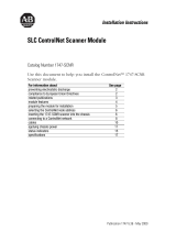
SLC ControlNet Scanner Module
Catalog Number 1747-SCNR
Use this document to help you install the ControlNet™ 1747-SCNR
Scanner module.
For information about See page
preventing electrostatic discharge 2
compliance to European Union Directives 2
related publications 3
module features 4
preparing the module for installation 5
selecting the ControlNet node address 6
inserting the 1747-SCNR scanner into the chassis 6
connecting to a ControlNet network 8
cables 10
applying chassis power 11
status indicators 17
specifications 18
AB PLCs

2 SLC ControlNet Scanner Module
Publication 1747-IN059A-EN-P - February 2001
Prevent Electrostatic Discharge
The scanner module is sensitive to electrostatic discharge.
Compliance to European Union Directives
If this product has the CE mark, it is approved for installation within
the European and EEA regions. It has been designed and tested to
meet the following directives.
EMC Directive
This product is tested to meet Council Directive 89/336/EEC
Electromagnetic Compatibility (EMC) and the following standards, in
whole or in part, documented in a technical construction file:
• EN 50081-2 EMC — Generic Emission Standard, Part 2 —
Industrial Environment
• EN 50082-2 EMC — Generic Immunity Standard, Part 2 —
Industrial Environment
This product is intended for use in an industrial environment.
ATTENTION
!
Electrostatic discharge can damage integrated circuits or
semiconductors if you touch backplane connector pins. Follow
these guidelines when you handle the module:
• touch a grounded object to discharge static potential
• wear an approved wrist-strap grounding device
• do not touch the backplane connector or connector pins
• do not touch circuit components inside the module
• if available, use a static-safe work station
• when not in use, keep the module in its static-shield bag

SLC ControlNet Scanner Module 3
Publication 1747-IN059A-EN-P - February 2001
Low Voltage Directive
This product is tested to meet Council Directive 73/23/EEC Low
Voltage by applying the safety requirements of EN 61131-2
Equipment Requirements and Tests.
For specific information required by EN 61131-2, see the appropriate
sections in this publication as well as the following Allen-Bradley
publications:
• Industrial Automation Wiring and Grounding Guidelines For
Noise Immunity, publication 1770-4.1
• Guidelines For Handling Lithium Batteries, publication AG-5.4
• Automation Systems Catalog, publication B113
This equipment is classified as open equipment and must be
installed (mounted) in an enclosure as a means of providing safety
protection.
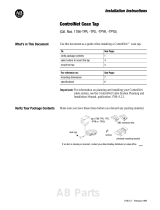
Related Publications
For software configuration information, refer to the ControlNet
1747-SCNR Reference Manual, publication 1747-RM623B-EN-P.
For planning and installation information, refer to the ControlNet
Cable System Planning and Installation Manual, publication
1786-6.2.1. If you need a copy of this manual, access the
Automation Bookstore website at
http://www.theautomationbookstore.com or the Manuals On line
website at http://www.ab.com/manuals.
For information on terminating ControlNet coaxial cables, refer to
Terminating Your ControlNet Coaxial Cables, CD number
CNET-DM001A-EN-C.
AB PLCs

4 SLC ControlNet Scanner Module
Publication 1747-IN059A-EN-P - February 2001
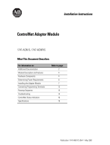
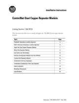
Identify Scanner Module Features
Use this illustration to identify the features of the 1747-SCNR
Scanner module.
Node Address and Status Display
Displays scanner node address and status
Module Status Indicator
Indicates whether the device is powered and is
functioning properly
ControlNet Redundant Media Ports
BNC connectors (Channels A and B)
Channel B
Status Indicator
Channel A
Status Indicator
ControlNet Network
Access Port
(NAP)-RJ45 connector
30751-M

SLC ControlNet Scanner Module 5
Publication 1747-IN059A-EN-P - February 2001
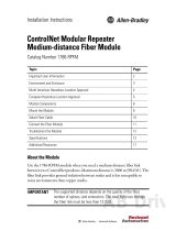
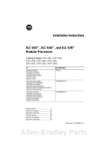
Prepare for Module Installation
Before you install your module, you need the following items:
Before you install the module, you must know how to:
• program and operate an Allen-Bradley SLC 500 programmable
controller
• install and configure the devices on your ControlNet network
Make Sure That Your Processor and Scanner Are Compatible
The 1747-SCNR Scanner module fits in any slot of the chassis except
for the left-most slot of the first chassis, which is reserved for the
SLC 500 processor.
Personal Computer with
Microsoft
Windows
RSNetWorx for
ControlNet
,
catalog number
9357-CNETL3
1747-SCNR Scanner Module
Reference Manual, publication
1747-RM623B-EN-P
SLC
1746 chassis with SLC
5/02, 5/03, 5/04, or 5/05 processor and
the appropriate configuration software
(RSLogix 500
)
ControlNet 1784-PCC (shown), or
1784-PCIC, or 1784-KTCX15, or
1770-KFC15
41523
AB PLCs

6 SLC ControlNet Scanner Module
Publication 1747-IN059A-EN-P - February 2001
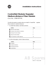
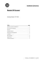
Select the ControlNet Node Address
Select the ControlNet node address of the 1747-SCNR by setting the
two 10-digit rotary switches on the top of the scanner. Valid switch
settings range from 01 through 99. Zero (00) is not a valid node
address.
Important: Since 00 is the default value from manufacturing, you
must change the default value when using the
scanner for the first time.
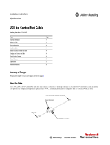
Insert the 1747-SCNR Scanner Into the Chassis
To insert the 1747-SCNR Scanner into the SLC chassis:
1. Turn off the SLC chassis power supply.
Important: If you disconnect the ac power, you lose the chassis
ground. Electrostatic damage (ESD) protection is lost.
ATTENTION
!
Do not install the 1747-SCNR Scanner module with the
chassis power supply on. Installing the module with the
chassis power supply on may damage the module.
Top View of Module
10-digit rotary switches: ones digit
10-digit rotary switches: tens digit
30752

SLC ControlNet Scanner Module 7
Publication 1747-IN059A-EN-P - February 2001
2. Select a slot for the module in the chassis. Choose any slot
except the left-most slot of the first chassis, which is reserved
for the SLC 500 processor.
3. Insert the module into the slot you have selected. We
recommend that you insert the 1747-SCNR Scanner as close to
the chassis power supply as possible.
4. Apply firm, even pressure to seat the module in the I/O
chassis backplane connectors.
5. Restore power to the SLC chassis.
30801-M
AB PLCs

8 SLC ControlNet Scanner Module
Publication 1747-IN059A-EN-P - February 2001
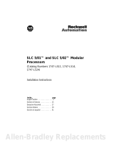
Connect to a ControlNet Network
Connect the 1747-SCNR Scanner module to a ControlNet network
via a tap with a 1m (39.4 in.) drop cable.
Four Allen-Bradley ControlNet taps are available from Rockwell
Automation as shown below.
We recommend that you use a tap with a straight connector—
1786-TPS or 1786-TPYS—when you attach a ControlNet 1747-SCNR
Scanner to a ControlNet network.
Important: Allen-Bradley ControlNet taps contain passive
electronics and must be purchased from Rockwell
Automation for the network to function properly.
After terminating your network segments, connect your node to the
network.
Straight T-tap
Straight Y-tap
Right-angle T-tap
Right-angle Y-tap
1786-TPS
1786-TPYS
1786-TPR
1786-TPYR
20094-M
A
A
B
Redundant media
Nonredundant media
30802-M

SLC ControlNet Scanner Module 9
Publication 1747-IN059A-EN-P - February 2001
Remove the tap’s dust cap—located on the straight or right-angle
connector—and set it aside.
For detailed information about planning and installing your
ControlNet system, see the following information sources.
If your network supports Connect the tap’s straight or right-angle connector
nonredundant media to the channel A connector on the scanner—channel B is not
used.
1
redundant media from trunk-cable A to channel A on the scanner and
from trunk-cable B to channel B on the scanner.
1. Rockwell Automation recommends using channel A for nonredundant media.
Source Source Number
ControlNet Coax Cable System Planning and Installation Manual 1786-6.2.1
ControlNet Media System Component List AG-2.2
ControlNet Coax Tap Installation Instructions 1786-5.7
ControlNet Network Access Cable Installation Instructions 1786-2.6
ControlNet Repeater Installation Instructions 1786-2.7
Industrial Automation Wiring and Grounding Guidelines 1770-4.1
Terminating Your ControlNet Coaxial Cables CNET-DM001A-EN-C
AB PLCs

10 SLC ControlNet Scanner Module
Publication 1747-IN059A-EN-P - February 2001
Cables
Several types of RG-6 quad-shield cables may be appropriate for
your ControlNet installation—depending on the environment factors
associated with your application and installation site.
The following Allen-Bradley ControlNet cable system components
are available from Rockwell Automation:
Important: Install all wiring for your ControlNet system in
accordance with the regulations contained in the
National Electronic Code (or applicable country
codes), state codes, and applicable municipal codes.
For detailed information about ControlNet cabling, see the
ControlNet System Overview, publication 1786-SO009A-EN-P and
the publications listed in the table on the previous page.
Item
1
Cat. No.
ControlNet Coax Tool Kit - ControlNet Coax Tool (enables you to make successful
coaxial cables)
1786-CTK
Coax Tap Kit Right-angle T-tap
Straight T-tap
Right-angle Y-tap
Straight Y-tap
1786-TPR
1786-TPS
1786-TPYR
1786-TPYS
Repeaters Dual channel coaxial repeater 1786-RPCD
Fiber Optic Repeaters
Low-voltage dc coax adapter 1786-RPA
Short-range fiber module 1786-RPFS
Medium-range fiber module 1786-RPFM
RG-6 Quad Shield Cable Standard-PVC CM-CL2 1786-RG6
ControlNet Network Access Cable–3.05 m (10 ft) 1786-CP
BNC Connectors Barrel (plug to plug) 1786-BNCP
BNC/RG-6 plug 1786-BNC
Bullet (jack to jack) 1786-BNCJ
Isolated-bulkhead (jack to jack) 1786-BNCJI
Terminators (BNC-75Ω) 1786-XT
1. For a complete list of Allen-Bradley ControlNet cable system components that are available from
Rockwell Automation and cable system components available from other suppliers, see the ControlNet
Media System Component List, publication AG-2.2.

SLC ControlNet Scanner Module 11
Publication 1747-IN059A-EN-P - February 2001
Apply Chassis Power
When you apply chassis power, the module address and status
display cycles through the following displays:
1. POST - The 1747-SCNR runs Power On Self Test.
2. 1111, 2222, etc. - The 1747-SCNR is executing its startup
sequence.
3. REV#, S/R, QXXX - The 1747-SCNR firmware version
temporarily displays after startup: S=series, R=revision, and
XXX=build number.
4. A#nn (where nn = ControlNet node address) then I/O or
I/OX (based on the number of connections configured and
established) then IDLE or RUN (based on the scanner mode).
Alphanumeric Display
The four character alphanumeric display provides you with
additional visual information about the current operating status of
the module.
The following tables describes problems that may occur while using
your 1747-SCNR, the probable causes, and the recommended action.
Node Address and
Status Display
30750-M
AB PLCs

12 SLC ControlNet Scanner Module
Publication 1747-IN059A-EN-P - February 2001
OK Indicator and Display Mnemonics
The OK indicator is handled consistently with the ControlNet
specifications for the Identity object.
Sequence OK
Indicator
Alpanumeric
Display
Module Status
Word (M1 file)
Description Probable
Cause
Recommended
Action
Startup Alternately
red/ green
POST N/A The
1747-SCNR
module is
running Power
On Self Test.
Power was
applied to the
module.
No action
required.
REV#
S/R
QXXX
N/A 1747-SCNR
Firmware
revision:
S=series
R=Revision
XXX=build
number. This is
a temporary
display after
startup.
Power was
applied to the
module.
No action
required.
Run time Green A#XX N/A ControlNet
node address
None No action
required.
I/O
0x26 All configured
connections
are
established.
None No action
required.
IDLE N/A The scanner is
in idle mode.
The SLC
processor or
adapter in
slot 0 is in
program
mode or the
Scanner
Mode
Command bit
of the Module
Command
word is clear
(O:x.0/10
where x is the
scanner slot
number).
If you want to
put the scanner
into run mode,
put the SLC
processor in
slot 0 into run
mode and set
the Scanner
Mode
Command bit of
the Module
Command word
(O:x.0/10) using
an
unconditional
OTE instruction.

SLC ControlNet Scanner Module 13
Publication 1747-IN059A-EN-P - February 2001
Sequence OK
Indicator
Alpanumeric
Display
Module Status
Word (M1 file)
Description Probable
Cause
Recommended
Action
Run time Green RUN N/A The scanner is
in run mode.
The SLC
processor in
slot 0 is in run
mode and the
Scanner
mode
Command bit
of the Module
Command
word is set
(O:x.0/10).
If you want to
put the scanner
into program
mode, either
put the SLC
processor in
slot 0 into
program mode
or clear the
Scanner Mode
Command bit of
the Module
Command word
(O:x.0/10).
EDIT N/A The scanlist in
the
1747-SCNR is
being modified.
Edits have
been enabled
with
RSNetWorx
for
ControlNet.
Note:
Previously
configured
connections
will be
reestablished
if lost. Newly
configured or
changed
connections
will not be
established
until edits are
accepted.
Finish modifying
the scanlist
with
RSNetWorx for
ControlNet and
then accept
edits.
Cancel edits
with
RSNetWorx for
ControlNet.
Flashing
Green
I/OX 0x20 The scanner is
not configured.
Module not
configured.
Use RSNetWorx
for ControlNet
to download a
new
configuration.
0x21 The current
configuration is
not valid.
The scanner is
not able to start
any scheduled
communication
to remote
devices. Only
unscheduled
communication
is possible.
Module not
configured
properly.
Use RSNetWorx
for ControlNet
to schedule the
existing
configuration.
Use RSNetWorx
for ControlNet
to download a
new
configuration.
AB PLCs

14 SLC ControlNet Scanner Module
Publication 1747-IN059A-EN-P - February 2001
Sequence OK
Indicator
Alpanumeric
Display
Module Status
Word (M1 file)
Description Probable
Cause
Recommended
Action
Run time Flashing
Green
I/O
I/O
I/O
I/O
0x22
0x23
0x24
0x25
Connections
are configured
but no
connections
are
established.
Connections
are configured
but only
25% are
successfully
established.
50%
75%
View the
Connection
Status screen
in RSNetWorx
for ControlNet
to see why
the
connections
are not
established.
Check to see if
the 1747-SCNR
and the remote
devices are
correctly
connected to
the ControlNet
network.
Module
bandwidth is
exceeded.
Reduce the
number of
scheduled
connections by:
- using a
discrete rack
connection
instead of
multiple
discrete module
connections
- combining
multiple I/O
racks into a
single I/O rack
- combining
multiple
peer-to-peer
messages into
one message.
Increase your
Network Update
Time and/or
increase the
Requested
Packet Intervals
for scheduled
data transfers.
Increase your
SLC 500 ladder
program scan
by adding more
logic.

SLC ControlNet Scanner Module 15
Publication 1747-IN059A-EN-P - February 2001
Sequence OK
Indicator
Alpanumeric
Display
Module Status
Word (M1 file)
Description Probable
Cause
Recommended
Action
Run time Flashing
Green
EDIT N/A The scanlist in
the 1747-SCNR
is being
modified.
Edits have
been enabled
with
RSNetWorx
for
ControlNet.
Note:
Previously
configured
connections
will be
reestablished
if lost. Newly
configured or
changed
connections
will not be
established
until edits are
accepted.
Finish
modifying the
scanlist with
RSNetWorx for
ControlNet and
then accept
edits.
Cancel edits
with
RSNetWorx for
ControlNet.
SIGM N/A A scanner
signature
mismatch has
been detected.
The
1747-SCNR
scanner
signature does
not match the
signature
stored in the
active keeper.
The scanner is
not able to start
any scheduled
communication
to remote
devices. Only
unscheduled
communication
is possible.
Module is not
configured
properly.
Use RSNetWorx
for ControlNet
to schedule the
existing
configuration.
Use RSNetWorx
for ControlNet
to download a
new
configuration.
AB PLCs

16 SLC ControlNet Scanner Module
Publication 1747-IN059A-EN-P - February 2001
Sequence OK
Indicator
Alpanumeric
Display
Module Status
Word (M1 file)
Description Probable
Cause
Recommended
Action
Errors Off None N/A Module is not
communicating
Power supply
fault.
Check power
supply, cable
connectors, and
seat module
firmly in
chassis.
Flashing
Green
N/A 0x43 Network error Cable error or
no other
nodes on the
network.
Verify network
cabling.
Red (Scrolling
display
showing fault
details)
N/A Module faulted Internal error
detected.
Record fault
details and
contact
Rockwell
Automation
representative
or distributor.
Flashing
Red
A#00
FLSH
CFG
ERAS
0x42 Module erased
network and
connection
configuration
stored in flash.
Network node
address set
to 00.
Power down
the module and
change the
address
switches.
DUPL
A#XX
0x44 Duplicate node
address
Another
device with
the same
ControlNet
address is on
the link.
Power down
the 1747-SCNR
module and
change the
network
address
switches to a
correct node.

SLC ControlNet Scanner Module 17
Publication 1747-IN059A-EN-P - February 2001
Status Indicators
The ControlNet status indicators inform you of the operational state
of the ControlNet network.
Indicator
Color
1
Probable Cause Recommended Action
A
and
B
Off No power No action required or apply power.
Steady Red Faulty unit Cycle power or reset unit. If fault
persists, contact your Rockwell
Automation representative or
distributor.
Alternating
Red/Green
Self-test No action required.
Alternating
Red/Off
Incorrect node
configuration or
duplicate ControlNet
node address
Check network address and other
ControlNet configuration parameters.
A
or
B
Off Channel disabled Program network for
redundant media, if required.
Steady
Green
Normal operation No action required.
Flashing
Green/Off
Temporary network
errors
• Check media for broken cables, loose
connectors, missing terminators, etc.
• If condition persists, refer to
ContolNet Cable Planning and
Installation Manual, publication
1786-6.2.1.
Flashing
Red/Off
Media fault • Check media for broken cables, loose
connectors, missing terminators, etc.
• If condition persists, refer to
ContolNet Cable Planning and
Installation Manual, publication
1786-6.2.1.
No other nodes
present on network
Add other nodes to the network.
Flashing
Red/Green
Incorrect node
address
Change 1747-SCNR node address so that it is
less than or equal to SMAX
2
.
Incorrect network
configuration
Reconfigure ControlNet network so that SMAX
2
is greater than or equal to 1747-SCNR node
address.
1. Definition of terms:
steady - indicator is on continuously in the defined state.
alternating - the two indicators alternate between the two defined states at the same time (applies to
both indicators
viewed together
); the two indicators are always in opposite states, out of phase.
flashing - the indicator alternates between the two defined states (applies to each indicator
viewed
independent
of the other); if both indicators are flashing, they flash together, in phase.
2. SMAX is the highest node address on a ControlNet network that can transmit scheduled data.
AB PLCs

18 SLC ControlNet Scanner Module
Publication 1747-IN059A-EN-P - February 2001
Hazardous Location Approval
The following information applies only to products marked with Hazardous
Location Approval, when operating in hazardous locations:
Products marked “CL I, DIV 2, GP A, B, C, D” are suitable for use in Class I Division
2 Groups A, B, C, D, Hazardous Locations and nonhazardous locations only. Each
product is supplied with markings on the rating nameplate indicating the hazardous
location temperature code. When combining products within a system, the most
adverse temperature code (lowest “T” number) may be used to help determine the
overall temperature code of the system. Combinations of equipment in your system
are subject to investigation by the local Authority Having Jurisdiction at the time of
installation.
WARNING
!
EXPLOSION HAZARD -
• Do not disconnect equipment unless power has been
removed or the area is known to be nonhazardous.
• Do not disconnect connections to this equipment unless
power has been removed or the area is known to be
nonhazardous. Secure any external connections that mate
to this equipment by using screws, sliding latches, threaded
connectors, or other means provided with this product.
• Substitution of components may impair suitability for Class
I, Division 2.
• If this product contains batteries, they must only be
changed in an area known to be nonhazardous.
WARNING
!
Use supply wires suitable for 30°C above surrounding ambient.
WARNING
!
When used in a Class I, Division 2, hazardous location, this
equipment must be mounted in a suitable enclosure with
proper wiring method that complies with the governing
electrical codes.

SLC ControlNet Scanner Module 19
Publication 1747-IN059A-EN-P - February 2001
Les informations suivantes ne concernent que les produits marqués pour
une utilisation en environnements dangereux :
Les produits marqués « CL I, DIV 2, GP A, B, C, D » ne conviennent qu’à une
utilisation en environnements de Classe I Division 2 Groupes A, B, C, D dangereux
et non dangereux. Chaque produit est livré avec des marquages sur sa plaque
d’identification qui indiquent le code de température pour les environnements
dangereux. Lorsque plusieurs produits sont combinés dans un système, le code de
température le plus défavorable (code de température le plus faible) peut être
utilisé pour déterminer le code de température global du système. Les
combinaisons d’équipements dans le système sont sujettes à inspection par les
autorités locales qualifiées au moment de l’installation.
AVERTISSEMENT
!
RISQUE D’EXPLOSION -
• Couper le courant ou s’assurer que l’environnement est
classé non dangereux avant de débrancher l’équipement.
• Couper le courant ou s’assurer que l’environnement est
classé non dangereux avant de débrancher les connecteurs.
Fixer tous les connecteurs externes reliés à cet équipement
à l’aide de vis, loquets coulissants, connecteurs filetés ou
autres moyens fournis avec ce produit.
• La substitution de composants peut rendre cet équipement
inadapté à une utilisation en environnement de Classe I,
Division 2.
• S’assurer que l’environnement est classé non dangereux
avant de changer les piles.
AVERTISSEMENT
!
Utiliser des fils d’alimentation qui conviennent à une
température de 30°C au-dessus de la température ambiante.
AVERTISSEMENT
!
Pour une utilisation en environnement de classe i, division 2
dangereux, cet equipement doit etre monte dans un boitier avec
un cablage approprie conforme aux normes electriques en
vigueur.
AB PLCs

Publication 1747-IN059A-EN-P - February 2001 PN 957445-91
Supersedes Publication 1747-5.36 - June 2000 © 2001 Rockwell International Corporation. Printed in the U.S.A.
Specifications
Allen-Bradley is a registered trademark of Rockwell Automation.
SLC is a trademark of Rockwell Automation.
ControlNet is a trademark of ControlNet International.
Microsoft Windows is a registered trademark of Microsoft Corporation.
RSNetWorx for ControlNet and RSLogix 500 are trademarks of Rockwell Software, Inc.
CSA logo is a registered trademark of the Canadian Standards Association.
Le sigle CSA est la marque déposée de l'Association des Standards pour le Canada.
Module Location Slot 1 or above
Module Defaults Node Address -00
Maximum Backplane Current 900 mA @ 5V dc
Isolated Voltage Optical Isolation between backplane and ControlNet channel 1
Megohm resistor from ControlNet channel to chassis
Environmental Conditions:
Operational Temperature
Storage Temperature
Relative Humidity
0-60°C (32-140°F)
-40 to 85°C (-40 to 185°F)
5-95% without condensation
Shock unpackaged 30g operational
50g non-operational
Vibration Unpackaged 5g from 10-150Hz
Immunity Radiated Fields 10 V/m
27 mHz-1000 mHz
Agency Certification
(when product or packaging is
marked)
Reference Manual 1747-RM623B-EN-P
marked for all applicable directives
Class 1 Division 2, groups A, B, C, D2
-
 1
1
-
 2
2
-
 3
3
-
 4
4
-
 5
5
-
 6
6
-
 7
7
-
 8
8
-
 9
9
-
 10
10
-
 11
11
-
 12
12
-
 13
13
-
 14
14
-
 15
15
-
 16
16
-
 17
17
-
 18
18
-
 19
19
-
 20
20


Allen-Bradley ControlNet 1747-SCNR Installation Instructions Manual
- Taper
- Installation Instructions Manual
dans d''autres langues
- English: Allen-Bradley ControlNet 1747-SCNR
Documents connexes
-
 Allen-Bradley ControlNet 1747-SCNR Installation Instructions Manual
-
 Allen-Bradley ControlNet Coax Tap 1786-TPR Installation Instructions Manual
-
 Allen-Bradley ControlNet 1747-ACNR15 Installation Instructions Manual
-
 Allen-Bradley ControlNet 1786-RPFM Installation Instructions Manual
-
 Allen-Bradley ControlNet 1786-RPFM Installation Instructions Manual
-
 Allen-Bradley 1784-U2CN Installation Instructions Manual
-
 Allen-Bradley ControlNet 1786-RPCD Installation Instructions Manual
-
 Allen-Bradley SLC 5/05 Installation Instructions Manual
-
 Allen-Bradley 1747-SN Installation Instructions Manual
-
 Allen-Bradley SLC 5/02 Installation Instructions Manual


