Allen-Bradley ControlNet 1786-RPFM Installation Instructions Manual
- Taper
- Installation Instructions Manual

1786-5.1
1 — February 1998
0
ControlNet Modular Repeater
Medium-distance Fiber Module
(Cat. No. 1786-RPFM)
Use this document as a guide when you install a ControlNet repeater
fiber module for medium distances:
• To install the module, read these sections:
Section Page
About The Fiber Module 2
European Union Directive Compliance 3
Mounting The Fiber Module 4
Wiring The Fiber Module 8
CSA Hazardous Location Approval 12
• For this information, refer to these sections:
Section Page
Indicators 10
Related Publications 11
Mounting Dimensions 11
Specifications 14
Installation Instruction
s
Installation Instruction
s
AB Spares

ControlNet Modular Repeater Medium-distance Fiber Module
2
1786-5.11
— February 1998
About The Fiber Module
Use this module when a medium-distance (distances of 3000m/9843ft)
fiber link is required between two ControlNet products. This fiber link
provides ground isolation between nodes and is less susceptible to noisy
environments than traditional cooper media.
Note: The distance that can be supported is dependent on the quality of
the fiber, number of splices, and connectors. The total loss of the
fiber link must be less than 13.3 dB. Typical systems of greater
than 3000m are possible.
The module provides:
• two fiber channels
• activity LED indicators for each fiber channel
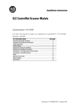
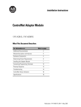
The figure below identifies the components of the module:
Indicators
Channel
1 fiber port
Module locking tab
Channel 2 fiber port
Right–side
backplane connector with
protective cover
The left side of the module (not shown here) also contains a backplane connector
.
Protective caps
30042–M

ControlNet Modular Repeater Medium-distance Fiber Module 3
1786-5.11
— February 1998
European Union Directive Compliance
If this product has the mark, it is approved for installation within
the European Union and EEA regions. It has been designed and tested to
meet the following directives.
EMC Directive
The module is tested to meet Council Directive 89/336 Electromagnetic
Compatibility (EMC) using a technical construction file and the
following standards, in whole or in part:
• EN 50081-2 EMC – Generic Emission Standard,
Part 2 – Industrial Environment
• EN 50082-2 EMC – Generic Immunity Standard,
Part 2 – Industrial Environment
The module described in this manual is intended for use in an
industrial environment.
Low Voltage Directive
The module is also designed to meet Council Directive 73/23 Low
Voltage, by applying the safety requirements of EN 61131–2
Programmable Controllers, Part 2 – Equipment Requirements and Tests.
For specific information that the above norm requires, see the
appropriate sections in this manual, as well as the following
Allen-Bradley publications:
• Industrial Automation Wiring and Grounding Guidelines,
publication 1770-4.1
• Guidelines for Handling Lithium Batteries, publication AG-5.4
• Automation Systems Catalog, publication B111
AB Spares

ControlNet Modular Repeater Medium-distance Fiber Module
4
1786-5.11
— February 1998
Mounting The Fiber Module
To mount the module on the DIN rail:
1. Position the module on a 35 x 7.5mm DIN rail (Allen-Bradley part
number 199-DR1; 46277-3; EN 50022) at a 30
o
angle.
30074–M
2. Hook the lip on the rear of the module onto the top of the DIN rail,
and rotate the module onto the rail.
30074–M

ControlNet Modular Repeater Medium-distance Fiber Module 5
1786-5.11
— February 1998
3. Press the module down onto the DIN rail until flush.
The locking tab should snap into position and lock the module to the
DIN rail.
4. If the module does not snap into position, use a screwdriver or similar
device to move the locking tab down while pressing the module flush
onto the DIN rail. Release the locking tab to lock the module in place.
If necessary, push up on the locking tab to lock.
AB Spares

ControlNet Modular Repeater Medium-distance Fiber Module
6
1786-5.11
— February 1998
5. Remove the protective backplane cap as shown in “Removing the
Protective Caps” on page 7.
6. Once attached to the DIN rail, slide modules to the left to mate with
the repeater adapter or another repeater module.
30043–M
!
ATTENTION: Make certain that the adapter and repeater
modules are secured together with DIN rail anchors.
Failure to do so may result in the loss of communications
and/or cause damage to the modules.
The total number of modules that can be attached to the repeater adapter
can not exceed four or the total power consumption of the modules can
not exceed 1.6A @ 5VDC, whichever comes first.
Important: If you exceed the module or power limit, you may cause
damage to the repeater adapter and modules.
Important: If this is the right–most module, a DIN rail latch must be
used on the right–side of the fiber module.
7. Connect the module wiring as shown in “Wiring The Fiber Module”
on page 8.

ControlNet Modular Repeater Medium-distance Fiber Module 7
1786-5.11
— February 1998
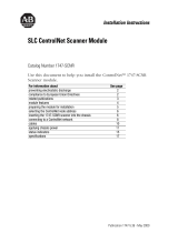
Removing the Protective Caps
1. Remove the protective caps from the fiber channels that will be used.
2. Save the caps for future use.
Protective
backplane
cap
Protective
cap
DIN rail
The left side of the module (not shown here) also contains a backplane connector
30049–M
If: Then:
a channel is not going to be used keep protective caps on channels to protect
unit from dust.
another module will be connected to the right
backplane connector
remove the protective backplane cap and save
cap for future use.
a module will not be connected to the right
backplane connector
leave the backplane cap attached.
AB Spares

ControlNet Modular Repeater Medium-distance Fiber Module
8
1786-5.11
— February 1998
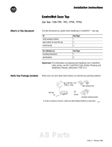
Wiring The Fiber Module
If only one channel is wired, you can use Channel 1 or Channel 2.
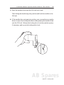
To wire the module for Channel 1:
1. Connect to Receive ST.
a. Align the knob of the ST cable connector with the groove of the
ST module connector, and insert the connector into
A.
A
B
(transmit)
(receive)
Channel
1
Channel 2
30044–M
b. Twist the Receive ST connector until the bayonet lug is locked
into place.
2. To connect to Transmit ST into
B, repeat Step 1.
"

ControlNet Modular Repeater Medium-distance Fiber Module 9
1786-5.11
— February 1998
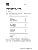
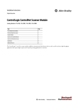
To wire the module for Channel 2:
1. Repeat the steps for Channel 1 and refer to the following figure.
OR
1786–RPA
A
B
CH1
CH2
A B
1786–RPFM 1786–RPA
A B
CH1
CH2
A B
1786–RPFM
Important: Be sure the fiber connected to A(receive) on one
1786–RPFM is connected to B(transmit) on the other
1786–RPFM. You can use Channel 1 or Channel 2 on
either module.
Important: Never connect the fiber cable between Channel 1 or
Channel 2 on the same repeater module, even between
channels from different modules on the same repeater.
!
Warning: Do not look directly into the fiber ports.
Light levels may cause damage to eyesight.
AB Spares

ControlNet Modular Repeater Medium-distance Fiber Module
10
1786-5.11
— February 1998
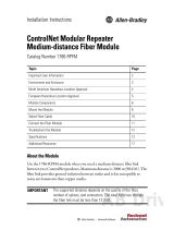
Indicators
The figure below identifies indicators on the module:
Channel
1 status
Channel 2 status
The table below defines Channel 1 and Channel 2 (individually) status
indications:
Status Indicator Probable Cause
Off No power or module is faulted
Green Channel operational
Flashing Green/Off No data activity on associated channel

ControlNet Modular Repeater Medium-distance Fiber Module 11
1786-5.11
— February 1998
Related Publications
The table below lists publications that you may want to refer to for
additional information:
Publication Publication Number
Industrial Automation Wiring and Grounding Guidelines 1770-4.1
ControlNet Coax Tap Installation Instructions 1786-5.7
ControlNet Cable System Planning and Installation Manual 1786-6.2.1
ControlNet Cable System Component List AG-2.2
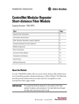
Mounting Dimensions
The figure below provides mounting dimensions for the module:
4.44
in.
(111 mm)
4.048 in.
(101.2 mm)
2
.
76
in.
(69 mm)
3.6 in.
(90 mm)
4.0 in.
(100 mm)
Specifications
AB Spares

ControlNet Modular Repeater Medium-distance Fiber Module
12
1786-5.11
— February 1998
CSA Hazardous Location Approval
CSA
certifies products for general use as well as for use in hazardous locations.
Actual CSA certification is
indicated by the product label
as shown below, and not by statements in any user documentation.
Example of the CSA certification product label
To comply with CSA certification for use in hazardous locations, the following information
becomes a part of the product literature for CSA-certified Allen-Bradley industrial control
products.
• This equipment is suitable for use in Class I, Division 2, Groups A, B, C, D, or
non-hazardous locations only.
• The products having the appropriate CSA markings (that is, Class I Division 2, Groups A, B,
C, D), are certified for use in other equipment where the suitability of combination (that is,
application or use) is determined by the CSA or the local inspection office having jurisdiction.
Important: Due to the modular nature of a PLC control system, the product with the highest
temperature rating determines the overall temperature code rating of a PLC control system in a
Class I, Division 2 location. The temperature code rating is marked on the product label as
shown.
T
e
mp
erature
c
o
d
e rat
ing
Look for temperature code
rating here
WARNING: Explosion hazard —
• Substitution of components may impair suitability for Class I, Division 2.
• Do not replace components unless power has been switched off or the
area is known to be non-hazardous.
• Do not disconnect equipment unless power has been switched off or the area is
k ow to be o - a ar ou .
!
The following warnings apply to products having CSA certification for use in hazardous locations.
D
o
n
ot
disc
o
nn
e
c
t e
q
u
ipm
e
n
t u
nl
e
ss
p
ower
h
a
s
bee
n
s
w
i
t
ch
e
d
off or t
h
e area
is
known to be non-hazardous.
• Do not disconnect connectors unless power has been switched off or the area is
known to be non-hazardous. Secure any user-supplied connectors that mate to
external circuits on an Allen-Bradley product using screws, sliding latches,
threaded connectors, or other means such that any connection can withstand
a 15 Newton (3.4 lb.) separating force applied for a minimum of one minute.
PLC
is a registered trademark of Allen-Bradley Company
, Inc.
CSA logo is a registered trademark of the Canadian Standards Association.

ControlNet Modular Repeater Medium-distance Fiber Module 13
1786-5.11
— February 1998
Approbation d’utilisation dans des emplacements dangereux par la CSA
L
a
CS
A
c
ert
i
f
i
e
l
e
s
p
ro
d
u
i
t
s
d
’ut
ilis
at
i
o
n
g
é
n
éra
l
e au
ssi
b
i
e
n
q
ue
c
eu
x
q
u
i
s
’ut
ilis
e
n
t
d
a
ns
d
e
s
emplacements dangereux.
La certification CSA en vigueur est indiquée par l’étiquette du produit
et
non par des af
firmations dans la documentation à l’usage des utilisateurs.
Exemple d’étiquette de certification d’un produit par la CSA
Pour
satisfaire à la certification de la CSA dans des endroits dangereux, les informations suivantes font
partie intégrante de la documentation des produits industriels de contrôle Allen-Bradley certifiés par la CSA.
•
Cet équipement convient à l’utilisation dans des emplacements de Classe 1, Division 2, Groupes A, B, C,
D, ou ne convient qu’à l’utilisation dans des endroits non dangereux.
•
Les produits portant le marquage approprié de la CSA (c’est à dire, Classe 1, Division 2, Groupes A, B,
C, D) sont certifiés à l’utilisation pour d’autres équipements où la convenance de combinaison
(application ou utilisation) est déterminée par la CSA ou le bureau local d’inspection qualifié.
Important: Par suite de la nature modulaire du système de contrôle PLC, le produit ayant le
taux le plus élevé de température détermine le taux d’ensemble du code de température du
système de contrôle d’un PLC dans un emplacement de Classe 1, Division 2. Le taux du code
de température est indiqué sur l’étiquette du produit.
Le taux du code de
température est indiqué ici
T
au
x
d
u
c
o
d
e
d
e te
mp
érature
AVERTISSEMENT: Risque d’explosion —
• La substitution de composants peut rendre ce matériel inacceptable pour
lesemplacements de Classe I, Division 2.
• Couper le courant ou s’assurer quel’emplacement est désigné non dangereux
avant de remplacer lescomposants.
• Avant de débrancher l’équipement, couper le courant ou s’assurer que
l’emplacement est désigné non dangereux.
• Avant de débrancher les connecteurs, couper le courant ou s’assurer que
l’emplacement est reconnu non dangereux. Attacher tous connecteurs fournis par
l’utilisateur et reliés aux circuits externes d’un appareil Allen-Bradley à l ’aide de vis,
loquets coulissants, connecteurs filetés ou autres moyens permettant aux
connexions de résister à une force de séparation de 15 newtons (3,4 lb. - 1,5 kg)
appliquée pendant au moins une minute.
L
e
s
a
v
ert
iss
e
m
e
n
t
s
s
u
iv
a
n
t
s
s
’a
ppliq
ue
n
t au
x
p
ro
d
u
i
t
s
aya
n
t
l
a
c
ert
i
f
ic
at
i
o
n
CS
A
p
our
l
eur
utilisation dans des emplacements dangereux.
!
Le
sigle CSA est la marque déposée de l’Association des Standards pour le Canada.
PLC est une marque déposée de Allen-Bradley Company
, Inc.
AB Spares

ControlNet Modular Repeater Medium-distance Fiber Module
14
1786-5.11
— February 1998
Specifications
The table below provides specifications for the module:
Communication Rate 5M bits/s
Indicators Channel 1 Status – Green
Channel 2 Status – Green
Backplane Power Requirements 400 mA
Environmental Conditions
Operating Temperature
Storage Temperature
Relative Humidity
Shock Operating
Non-operating
Vibration
0 to 60
o
C (32 to 140
o
F)
–40 to 85
o
C (–40 to 185
o
F)
5 to 95% non-condensing
30 g peak acceleration, 11($1)ms pulse width
50 g peak acceleration, 11($1)ms pulse width
Tested 5 g @ 10-500Hz per IEC 68-2-6
Fiber Type
Fiber Termination Type
Fiber Operating Wavelength
Optical Power Budget
62.5/125 micron
ST
r
(plastic or ceramic)
1300 nm
13.3 dB
➀
Agency Certification
(when product or marked)
marked for all applicable directives
Class 1 Div 2 Hazardous
listed
Class 1 Div 2 Hazardous
➀
This includes all loss associated with the fiber link, including: splices, fiber attenuation, bulkhead connectors,
and the 1786–RPFM ST terminations.
ControlNet is a trademark of ControlNet International
STR is a trademark of AT&T.
Worldwide
r
epresentation.
1786-5.11
— February 1998
Supersedes
1786-5.11 – July 1997
955131-12
Copyright 1997 Allen-Bradley Company, Inc. Printed i USA
-
 1
1
-
 2
2
-
 3
3
-
 4
4
-
 5
5
-
 6
6
-
 7
7
-
 8
8
-
 9
9
-
 10
10
-
 11
11
-
 12
12
-
 13
13
-
 14
14


Allen-Bradley ControlNet 1786-RPFM Installation Instructions Manual
- Taper
- Installation Instructions Manual
dans d''autres langues
- English: Allen-Bradley ControlNet 1786-RPFM
Documents connexes
-
 Allen-Bradley ControlNet 1786-RPFM Installation Instructions Manual
-
 Allen-Bradley ControlNet 1786-RPFM Installation Instructions Manual
-
 Allen-Bradley ControlNet 1786-RPFS Installation Instructions Manual
-
 Allen-Bradley ControlNet 1747-SCNR Installation Instructions Manual
-
 Allen-Bradley ControlNet 1747-SCNR Installation Instructions Manual
-
 Allen-Bradley ControlNet Coax Tap 1786-TPR Installation Instructions Manual
-
 Allen-Bradley ControlLogix ControlNet Scanner Module Installation Instructions Manual
-
 Allen-Bradley ControlNet 1747-ACNR15 Installation Instructions Manual
-
 Allen-Bradley ControlNet-to-DeviceNet 1788-CN2DN Installation Instructions Manual
-
 Allen-Bradley ControlNet 1786-RPCD Installation Instructions Manual


