La page est en cours de chargement...

Installation Instructions
ControlNet Modular Repeater
Short-distance Fiber Module
Catalog Number 1786-RPFS
About the Module
Use the 1786-RPFS module when you need a short-distance fiber link between
two ControlNet products. Maximum distance is 300 m (984 ft). The fiber link
provides ground isolation between nodes and is less susceptible to noisy
environments than copper media.
Topic Page
Important User Information 2
Environment and Enclosure 3
North American Hazardous Location Approval 4
European Hazardous Location Approval 5
Module Components 6
Mount the Module 6
Connect the Fiber Module 10
Troubleshoot the Module 11
Specifications 12
Additional Resources 16
IMPORTANT
The supported distance depends on the quality of the fiber,
number of splices, and connectors. The total light loss through
the fiber link must be less than 4.2 dB.

2 ControlNet Modular Repeater Short-distance Fiber Module
Rockwell Automation Publication 1786-IN012B-EN-P - November 2010
Important User Information
Solid-state equipment has operational characteristics differing from those of electromechanical
equipment. Safety Guidelines for the Application, Installation and Maintenance of Solid State Controls
(Publication SGI-1.1
available from your local Rockwell Automation sales office or online at
http://www.rockwellautomation.com/literature/
) describes some important differences between
solid-state equipment and hard-wired electromechanical devices. Because of this difference, and also
because of the wide variety of uses for solid-state equipment, all persons responsible for applying this
equipment must satisfy themselves that each intended application of this equipment is acceptable.
In no event will Rockwell Automation, Inc. be responsible or liable for indirect or consequential damages
resulting from the use or application of this equipment.
The examples and diagrams in this manual are included solely for illustrative purposes. Because of the
many variables and requirements associated with any particular installation, Rockwell Automation, Inc.
cannot assume responsibility or liability for actual use based on the examples and diagrams.
No patent liability is assumed by Rockwell Automation, Inc. with respect to use of information, circuits,
equipment, or software described in this manual.
Reproduction of the contents of this manual, in whole or in part, without written permission of Rockwell
Automation, Inc., is prohibited.
Throughout this manual, when necessary, we use notes to make you aware of safety considerations.
WARNING: Identifies information about practices or circumstances that can cause an
explosion in a hazardous environment, which may lead to personal injury or death,
property damage, or economic loss.
ATTENTION: Identifies information about practices or circumstances that can lead to
personal injury or death, property damage, or economic loss. Attentions help you identify
a hazard, avoid a hazard and recognize the consequences.
SHOCK HAZARD: Labels may be on or inside the equipment, for example, drive or motor,
to alert people that dangerous voltage may be present.
BURN HAZARD: Labels may be on or inside the equipment, for example, drive or motor,
to alert people that surfaces may reach dangerous temperatures.
IMPORTANT Identifies information that is critical for successful application and understanding of the
product.

ControlNet Modular Repeater Short-distance Fiber Module 3
Rockwell Automation Publication 1786-IN012B-EN-P - November 2010
Environment and Enclosure
ATTENTION: This equipment is intended for use in a Pollution
Degree 2 industrial environment, in overvoltage Category II
applications (as defined in IEC publication 60664-1), at altitudes up
to 2000 m (6562 ft) without derating.
This equipment is considered Group 1, Class A industrial equipment
according to IEC/CISPR Publication 11. Without appropriate
precautions, there may be difficulties with electromagnetic
compatibility in residential and other environments due to conducted
and radiated disturbances.
This equipment is supplied as open-type equipment. It must be
mounted within an enclosure that is suitably designed for those
specific environmental conditions that will be present and
appropriately designed to prevent personal injury resulting from
accessibility to live parts. The enclosure must have suitable
flame-retardant properties to prevent or minimize the spread of flame,
complying with a flame spread rating of 5VA, V2, V1, V0 (or
equivalent) if non-metallic. The interior of the enclosure must be
accessible only by the use of a tool. Subsequent sections of this
publication may contain additional information regarding specific
enclosure type ratings that are required to comply with certain
product safety certifications.
In addition to this publication, see:
• Industrial Automation Wiring and Grounding Guidelines, Rockwell
Automation publication 1770-4.1
, for additional installation
requirements.
• NEMA Standard 250 and IEC 60529, as applicable, for explanations
of the degrees of protection provided by different types of enclosure.
ATTENTION: This equipment is not resistant to sunlight or other
sources of UV radiation.

4 ControlNet Modular Repeater Short-distance Fiber Module
Rockwell Automation Publication 1786-IN012B-EN-P - November 2010
North American Hazardous Location Approval
The following information applies
when operating this equipment in
hazardous locations.
Informations sur l’utilisation de cet
équipement en environnements
dangereux.
Products marked "CL I, DIV 2, GP A, B, C, D" are
suitable for use in Class I Division 2 Groups A, B, C,
D, Hazardous Locations and nonhazardous
locations only. Each product is supplied with
markings on the rating nameplate indicating the
hazardous location temperature code. When
combining products within a system, the most
adverse temperature code (lowest "T" number) may
be used to help determine the overall temperature
code of the system. Combinations of equipment in
your system are subject to investigation by the
local Authority Having Jurisdiction at the time of
installation.
Les produits marqués "CL I, DIV 2, GP A, B, C, D" ne
conviennent qu'à une utilisation en environnements
de Classe I Division 2 Groupes A, B, C, D dangereux et
non dangereux. Chaque produit est livré avec des
marquages sur sa plaque d'identification qui indiquent
le code de température pour les environnements
dangereux. Lorsque plusieurs produits sont combinés
dans un système, le code de température le plus
défavorable (code de température le plus faible) peut
être utilisé pour déterminer le code de température
global du système. Les combinaisons d'équipements
dans le système sont sujettes à inspection par les
autorités locales qualifiées au moment de
l'installation.
WARNING:
Explosion Hazard -
•Do not disconnect equipment
unless power has been removed
or the area is known to be
nonhazardous.
•Do not disconnect connections to
this equipment unless power has
been removed or the area is
known to be nonhazardous.
Secure any external connections
that mate to this equipment by
using screws, sliding latches,
threaded connectors, or other
means provided with this product.
•Substitution of components may
impair suitability for Class I,
Division 2.
•If this product contains batteries,
they must only be changed in an
area known to be nonhazardous.
AVERTISSEMENT:
Risque d’Explosion –
•Couper le courant ou s'assurer que
l'environnement est classé non
dangereux avant de débrancher
l'équipement.
•Couper le courant ou s'assurer que
l'environnement est classé non
dangereux avant de débrancher les
connecteurs. Fixer tous les
connecteurs externes reliés à cet
équipement à l'aide de vis, loquets
coulissants, connecteurs filetés ou
autres moyens fournis avec ce
produit.
•La substitution de composants peut
rendre cet équipement inadapté à
une utilisation en environnement de
Classe I, Division 2.
•S'assurer que l'environnement est
classé non dangereux avant de
changer les piles.

ControlNet Modular Repeater Short-distance Fiber Module 5
Rockwell Automation Publication 1786-IN012B-EN-P - November 2010
European Hazardous Location Approval
Prevent Electrostatic Discharge
European Zone 2 Certification (The following applies when the product bears the
Ex Marking.)
This equipment is intended for use in potentially explosive atmospheres as defined by
European Union Directive 94/9/EC and has been found to comply with the Essential Health
and Safety Requirements relating to the design and construction of Category 3 equipment
intended for use in potentially explosive atmospheres, given in Annex II to this Directive.
Compliance with the Essential Health and Safety Requirements has been assured by
compliance with EN 60079-15 and EN 60079-0.
WARNING: You must follow these guidelines:
• This equipment must be installed in an enclosure providing at least
IP54 protection when applied in Zone 2 environments.
• This equipment shall be used within its specified ratings defined by
Rockwell Automation.
• Do not disconnect equipment unless power has been removed or
the area is known to be nonhazardous.
ATTENTION: This equipment is sensitive to electrostatic discharge,
which can cause internal damage and affect normal operation.
Follow these guidelines when you handle this equipment:
• Touch a grounded object to discharge potential static.
• Wear an approved grounding wriststrap.
• Do not touch connectors or pins on component boards.
• Do not touch circuit components inside the equipment.
• Use a static-safe workstation, if available.
• Store the equipment in appropriate static-safe packaging when not
in use.

6 ControlNet Modular Repeater Short-distance Fiber Module
Rockwell Automation Publication 1786-IN012B-EN-P - November 2010
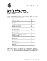
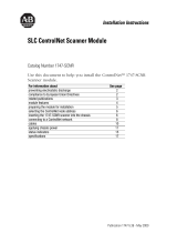
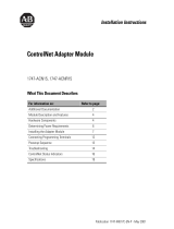
Module Components
The illustration shows the components that comprise the 1786-RPFS module.
Mount the Module
Mount the module on a 35 x 7.5 mm (1.38 x 0.30 in.) DIN rail, Allen-Bradley
part number 199-DR1, 46277, EN 50022.
ATTENTION: This product is grounded through the DIN rail to
chassis ground. Use zinc plated yellow-chromate steel DIN rail to
assure proper grounding. The use of other DIN rail materials (for
example, aluminum or plastic) that can corrode, oxidize, or are poor
conductors, can result in improper or intermittent grounding.
Secure DIN rail to mounting surface approximately every
200 mm (7.8 in.) and use end-anchors appropriately.
TIP
Horizontal mounting is preferred. Vertical mounting is allowed.
We recommend that the 1786-RPA/B repeater adapter module be
mounted at the top if vertical mounting is chosen.
.
Right-side
Backplane
Connector with
Protective Cap
30073
Channel 2 Fiber Port
Module Locking Tab
Channel 1 Fiber Port
Protective Caps
Indicators
Both sides of the module contain a backplane connector.

ControlNet Modular Repeater Short-distance Fiber Module 7
Rockwell Automation Publication 1786-IN012B-EN-P - November 2010
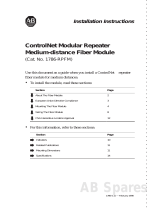
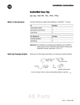
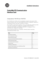
Mounting Dimensions
1. Position the module at a 30
° angle.
2. Hook the lip on the back of the module to the top of the DIN rail and
press the bottom of the module until the locking tab snaps securely in
place.
TIP
Use a screwdriver to move the locking tab downward, if the
module is not secured.
111
(4.44)
100
(4.0)
69
(2.76)
96.8
(3.87)
90
(3.6)
30082
All dimensions are in mm (in.).
30075

8 ControlNet Modular Repeater Short-distance Fiber Module
Rockwell Automation Publication 1786-IN012B-EN-P - November 2010
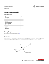
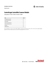
3. If necessary, remove the protective caps from the transmit and receive
fiber channels.
WARNING: If you insert or remove the module while backplane
power is on, an electrical arc can occur. This could cause an
explosion in hazardous location installations.
Be sure that power is removed or the area is nonhazardous
before proceeding.
If Then
You will connect another module Remove the protective backplane cap.
You will not use the backplane connector Keep the protective cap on to protect the
connector from dust.
ATTENTION: Do not discard the end cap. Use this end cap to
cover the exposed interconnections on the last module on the
DIN rail. Failure to do so could result in equipment damage.
DIN Rail
Protective Cap
30078
Protective Backplane Cap
Both sides of the module contain a backplane connector.

ControlNet Modular Repeater Short-distance Fiber Module 9
Rockwell Automation Publication 1786-IN012B-EN-P - November 2010
4. If applicable, slide the module to the left to mate with the repeater
adapter or another repeater module.
You can attach a maximum of four modules to the repeater adapter, or, the
number of modules whose total power consumption does not exceed
1.6 A @ 5V DC, whichever occurs first.
If Then
You will use a channel Remove the protective cap from the
channel.
You will not use a channel Keep the protective cap on to protect the
channel from dust.
You place the module in storage Keep the protective cap on to protect the
channel from dust.
IMPORTANT
Make certain that you secure the adapter and repeater modules
with DIN-rail anchors. If you do not, loss of communication or
module damage may result.
Consult with your local distributor for attenuation specifications
before you purchase your fiber media components.
IMPORTANT
If you exceed the module or power limit, you may damage the
repeater adapter and modules.
30077

10 ControlNet Modular Repeater Short-distance Fiber Module
Rockwell Automation Publication 1786-IN012B-EN-P - November 2010
Connect the Fiber Module
This module requires a pre-terminated zipcord wiring kit. The kits are offered in
a variety of lengths. Consult with your local distributor for attenuation
specifications before you purchase your fiber media components.
The zipcord uses a duplex cable that contains two separate fibers, one for
transmit and one for receive. If you are wiring only one channel, you can use
either channel 1 or channel 2.
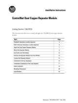
1. Hold down the latch and insert the channel 1 zipcord connector into the
A and B connectors until the pins and latch lock into place.
Make certain you insert the blue pin, receive, of the zipcord connector
in A and the black pin, transmit, into B.
2. Hold down the latch and insert the other end of the duplex cable into
another module by using either channel 1 or channel 2 of the
other module.
IMPORTANT
The duplex cable is manufactured with the fiber reversed on
opposite ends. This automatically connects channel A of one unit
to channel B of the other. Do not connect more than one duplex
fiber or two simplex fibers between the same modular repeaters,
even if they are from different modules on the same repeater.
30079
Channel 1, A and B
Channel 2, A and B

ControlNet Modular Repeater Short-distance Fiber Module 11
Rockwell Automation Publication 1786-IN012B-EN-P - November 2010
Troubleshoot the Module
Use the channel 1 or 2 status indicators to check module status and troubleshoot
the module.
ATTENTION: Under certain conditions, viewing the optical port
may expose the eye to hazard. When viewed under some
conditions, the optical port may expose the eye beyond the
maximum permissible exposure recommendations
Indicator Probable Cause
Off Repeater not connected to the power supply.
Green Channel is operating normally.
Flashing Green No activity on the channel.
ATTENTION: Class 1 laser product. Laser radiation is present when
the system is open and interlocks bypassed. Only trained and qualified
personnel should be allowed to install, replace, or service this
equipment.
30081
Channel 1 Status
Channel 2 Status

12 ControlNet Modular Repeater Short-distance Fiber Module
Rockwell Automation Publication 1786-IN012B-EN-P - November 2010
Specifications
Technical Specifications - 1786-RPFS
Attribute Value
All supply voltages or voltage ranges Backplane: 5V DC, 300 mA
Dissipation 2 W
Communication rate 5 Mbps
Mounting orientation Any mounting orientation
Minimum enclosure size (HxWxD), approx 304.8 x 196.8 x 101.6 mm
(12 x 7.75 x 4 in.)
Fiber type 200/230 micron HCS (hard-clad silica)
Power level
TX power, min
RX responsivity, min
(-17 dBm) @ 0…70 °C (32…158 °F) into
200 micron HCS fiber
-21.3 dBm @ 0…70 °C (32…158 °F)
Fiber temp range 200 micron HCS: -20…85 °C (-4…185 °F)
Bend radius 38 mm (1.5 in.), during installation
10 mm (0.4 in.) during operation
Tension, max 490 N (110 lb), during installation
310 N (70 lb), during operation
Connection 2 dB (mated pair) when added between
transmitter and receiver
Optical power budget 4.2 dB
(1)
Fiber termination type ST Versa V-System
Fiber operation wavelength 650 nm (red)
Transmitter output <5 mW/nm

ControlNet Modular Repeater Short-distance Fiber Module 13
Rockwell Automation Publication 1786-IN012B-EN-P - November 2010
Enclosure type rating None (open-style)
North American temp code T5
IEC temp code T4
(1) This includes all loss associated with the fiber link, including splices, fiber attenuation, bulkhead
connectors, and the ST terminations.
Environmental Specifications - 1786-RPFS
Attribute Value
Temperature, operating
IEC 60068-2-1 (Test Ad, Operating Cold),
IEC 60068-2-2 (Test Bd, Operating Dry Heat),
IEC 60068-2-14 (Test Nb, Operating Thermal
Shock)
0…60 °C (32…140 °F)
Temperature, surrounding air, max 60 °C (140 °F)
Temperature, nonoperating
IEC 60068-2-1 (Test Ab, Unpackaged
Nonoperating Cold),
IEC 60068-2-2 (Test Bb, Unpackaged
Nonoperating Dry Heat),
IEC 60068-2-14 (Test Na, Unpackaged
Nonoperating Thermal Shock)
-40…85 °C (-40…185 °F)
Relative humidity
IEC 60068-2-30 (Test Db, Unpackaged Damp
Heat)
5...95% noncondensing
Vibration
IEC60068-2-6 (Test Fc, Operating)
5 g @ 10...500 Hz
Technical Specifications - 1786-RPFS
Attribute Value

14 ControlNet Modular Repeater Short-distance Fiber Module
Rockwell Automation Publication 1786-IN012B-EN-P - November 2010
Shock, operating
IEC60068-2-27 (Test Ea, Unpackaged Shock)
30 g
Shock, nonoperating
IEC60068-2-27 (Test Ea, Unpackaged Shock)
50 g
Emissions
CISPR 11
Group 1, Class A
ESD immunity
IEC 61000-4-2
4 kV contact discharges
8 kV air discharges
Radiated RF immunity
IEC 61000-4-3
10V/m with 1 kHz sine-wave 80% AM from
80…2000 MHz
10V/m with 200 Hz 50% Pulse 100% AM at
900 and 1890 MHz
3V/m with 1 kHz sine-wave 80% AM from
2000…2700 MHz
Certifications
(1)
- 1786-RPFS
Certification
(2)
Value
UL UL Listed Industrial Control Equipment.
See UL File E65584.
CSA CSA Certified Process Control Equipment.
See CSA File LR54689C.
CSA Certified Process Control Equipment for
Class I, Division 2 Group A, B, C, D
Hazardous Locations. See CSA File
LR69960C.
FM FM Approved Equipment for use in Class I
Division 2 Group A,B,C,D Hazardous
Locations
Environmental Specifications - 1786-RPFS
Attribute Value

ControlNet Modular Repeater Short-distance Fiber Module 15
Rockwell Automation Publication 1786-IN012B-EN-P - November 2010
CE European Union 2004/108/EC EMC
Directive, compliant with:
• EN 61326-1; Meas./Control/Lab.,
Industrial Requirements
• EN 61000-6-2; Industrial Immunity
• EN 61000-6-4; Industrial Emissions
• EN 61131-2; Programmable Controllers
(Clause 8, Zone A & B)
C-Tick Australian Radiocommunications Act,
compliant with:
• AS/NZS CISPR 11; Industrial Emissions
Ex European Union 94/9/EC ATEX Directive,
compliant with:
• EN 60079-15; Potentially Explosive
Atmospheres, Protection ‘n’
• EN 60079-0; General Requirements
• II 3 G Ex nA IIC T4X
(1) When product is marked.
(2) See the Product Certification link at http://www.ab.com
for Declarations of Conformity, Certificates,
and other certification details.
Certifications
(1)
- 1786-RPFS
Certification
(2)
Value

Publication 1786-IN012B-EN-P - November 2010 PN-83809
Supersedes Publication 1786-5.12 - February 1998 Copyright © 2010 Rockwell Automation, Inc. All rights reserved. Printed in the U.S.A.
Allen-Bradley, Rockwell Software, Rockwell Automation, and TechConnect are trademarks of Rockwell Automation, Inc.
Trademarks not belonging to Rockwell Automation are property of their respective companies.
Rockwell Otomasyon Ticaret A.Ş., Kar Plaza İş Merkezi E Blok Kat:6 34752 İçerenköy, İstanbul, Tel: +90 (216) 5698400
Additional Resources
These documents contain additional information concerning related Rockwell
Automation products.
You can view or download publications at
http://www.rockwellautomation.com/literature/. To order paper copies of
technical documentation, contact your local Rockwell Automation distributor
or sales representative.
Documentation Feedback
Your comments will help us serve your documentation needs better. If you have any suggestions on how to
improve this document, complete this form, publication RA-DU002
, available at
http://www.rockwellautomation.com/literature/
Resource Description
ControlNet Coax Taps Installation
Instructions, publication 1786-IN007
Document contains procedures and
specifications for the installation of
ControlNet coaxial taps.
ControlNet Coax Media Planning and
Installation Guide, publication CNET-IN002
Document describes the components and
topologies for creating a ControlNet coax
media system.
ControlNet Fiber Media Planning and
Installation Guide, publication CNET-IN001
Document describes the components and
topologies for creating a ControlNet fiber
media system.
Industrial Automation Wiring and
Grounding Guidelines,
publication 1770-IN041
More information on proper wiring and
grounding techniques.
/