Allen-Bradley ControlNet 1786-RPFM Installation Instructions Manual
- Taper
- Installation Instructions Manual

Publication 1786-IN011B-EN-P - October 2000
Installation Instructions
ControlNet Modular Repeater
Medium Distance Fiber Module
Cat. Nos. 1786-RPFM
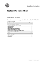
Use this document as a guide when you install a ControlNet™ repeater fiber module for
medium distances. This document contains:
This product is associated with a planning and installation guide, publication
CNET-IN001A-EN-P, The ControlNet Fiber Media Planning and Installation Guide.
To view it, visit www.ab.com/manuals or www.theautomationbookstore.com
Topic: Page:
Important User Information 2
EMC Directive 3
Low Voltage Directive 3
Fiber Optic Safety Statements 4
Rockwell Automation Support 4
About the Fiber Module 6
Mount the Fiber Module 7
Remove the Protective Caps 10
Choose Fiber Cable Types 11
Specifications for 1786-RPFM Fiber Optic Cable 12
Estimate Cable Lengths 12
Connect the Fiber Cable 13
Example Topology 14
Status Indicators 15
Related Publications 16
Mounting Dimensions 16
Specifications 17
Hazardous Location Approval 19
AB PLCs

2 ControlNet Modular Repeater Medium Distance Fiber Module
Publication 1786-IN011B-EN-P - October 2000
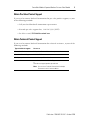
You can purchase a printed manual by:
• contacting your local distributor or Rockwell Automation representative
• visiting www.theautomationbookstore.com and placing an order
• calling 800.963.9548 (USA/Canada) or 001.320.725.1574 (outside USA/Canada)
Important User Information
Because of the variety of uses for the products described in this publication, those
responsible for the application and use of this control equipment must satisfy
themselves that all necessary steps have been taken to assure that each application
and use meets all performance and safety requirements, including any applicable
laws, regulations, codes and standards.
The illustrations, charts, sample programs and layout examples shown in this guide
are intended solely for purposes of example. Since there are many variables and
requirements associated with any particular installation, Allen-Bradley does not
assume responsibility or liability (to include intellectual property liability) for actual
use based upon the examples shown in this publication.
Allen-Bradley publication SGI-1.1, Safety Guidelines for the Application, Installation
and Maintenance of Solid-State Control (available from your local Allen-Bradley
office), describes some important differences between solid-state equipment and
electromechanical devices that should be taken into consideration when applying
products such as those described in this publication.
Reproduction of the contents of this copyrighted publication, in whole or part,
without written permission of Rockwell Automation, is prohibited.
Throughout this manual we use notes to make you aware of safety considerations:
Attention statements help you to:
• identify a hazard
• avoid a hazard
• recognize the consequences
Allen-Bradley is a trademark of Rockwell Automation
ATTENTION
!
Identifies information about practices or circumstances that can
lead to personal injury or death, property damage or economic
loss
IMPORTANT
Identifies information that is critical for successful application
and understanding of the product.

ControlNet Modular Repeater Medium Distance Fiber Module 3
Publication 1786-IN011B-EN-P - October 2000
European Communities (EC) Directive Compliance
If this product has the CE mark it is approved for installation within the European
Union and EEA regions. It has been designed and tested to meet the following
directives.
EMC Directive
This product is tested to meet the Council Directive 89/336/EC Electromagnetic
Compatibility (EMC) by applying the following standards, in whole or in part,
documented in a technical construction file:
• EN 50081-2 EMC — Generic Emission Standard, Part 2 — Industrial
Environment
• EN 50082-2 EMC — Generic Immunity Standard, Part 2 — Industrial
Environment
This product is intended for use in an industrial environment.
Low Voltage Directive
This product is tested to meet Council Directive 73/23/EEC Low Voltage, by
applying the safety requirements of EN 61131-2 Programmable Controllers, Part 2 -
Equipment Requirements and Tests. For specific information required by EN
61131-2, see the appropriate sections in this publication, as well as the
Allen-Bradley publication Industrial Automation Wiring and Grounding Guidelines,
publication 1770-4.1.
This equipment is classified as open equipment and must be mounted in an
enclosure during operation to provide safety protection.
AB PLCs

4 ControlNet Modular Repeater Medium Distance Fiber Module
Publication 1786-IN011B-EN-P - October 2000
Fiber Optic Safety Statements
Rockwell Automation Support
Rockwell Automation offers support services worldwide, with over 75 sales/support
offices, over 500 authorized distributors, and 260 authorized systems integrators
located throughout the United States alone, plus Rockwell Automation
representatives in every major country around the world. Contact your local
Rockwell Automation representative for:
• sales and order support
• product technical training
• warranty support
• support service agreements
ATTENTION
!
Do not look directly into the fiber ports. Light levels will cause
damage to your eyesight.
ATTENTION
!
"Hazardous areas require the use of specifically designed
products. This product is designed for Class I, Division 2
hazardous environments, and nonhazardous environments
only. Allen-Bradley provides similar products which are
intrinsically safe and are suitable for more hazardous
environments. Use the appropriate products that are designed
for the specific hazardous environments that your installation
requires.
In intrinsically safe applications, consult with your local safety
coordinator, and publication CNET-IN003A-US-P, the
ControlNet EX Media Planning and Installation Manual because
you need specific products on both ends of the fiber link."

ControlNet Modular Repeater Medium Distance Fiber Module 5
Publication 1786-IN011B-EN-P - October 2000
Obtain Pre-Sales Product Support
If you need to contact Rockwell Automation for pre-sales product support, try one
of the following methods:
• Call your local Rockwell Automation representative
• Network pre-sales support line, 1.440.646.3638 (3NET)
• Pre-Sales e-mail, [email protected]l.com
Obtain Technical Product Support
If you need to contact Rockwell Automation for technical assistance, try one of the
following methods:
Type of technical support: Access at:
Personalized Service Call your local Rockwell Automation representative
Post-sales Technical Support 1.440.646.5800
Email your questions to racleaskt[email protected]m
Internet site www.ab.com, then select Product Support
or
www.ab.com/support/products/pccards.html
Note: You can access Rockwell Automation Knowledge
Documents from this internet address.
AB PLCs

6 ControlNet Modular Repeater Medium Distance Fiber Module
Publication 1786-IN011B-EN-P - October 2000
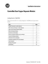
About the Fiber Module
Use this module when a medium-distance (distances of 3000m/ 9843ft) fiber link is
required between two ControlNet products. This fiber link provides ground
isolation between nodes and is less susceptible to noisy environments than
traditional copper media.
The module provides:
• two fiber channels
• activity LED indicators for each fiber channel
Figure 1 Components of the Module
IMPORTANT
The distance that can be supported is dependent on the quality
of the fiber, number of splices, and connectors. The total loss of
the fiber link must be less than 13.3 dB.
Indicators
Protective caps
Channel 1 fiber port
Module locking tab
Channel 2 fiber port
Right-side
backplane
connector with
protective cover
The left side of the modules (not shown here) also contains a backplane connector
42595

ControlNet Modular Repeater Medium Distance Fiber Module 7
Publication 1786-IN011B-EN-P - October 2000
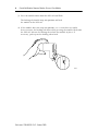
Mount the Fiber Module
To mount the module on the DIN rail:
1. Position the module on a 35 x 7.5mm DIN rail (Allen- Bradley part number
199- DR1; 46277- 3; EN 50022) at a 30
o
angle.
2. Hook the lip on the rear of the module onto the top of the DIN rail, and
rotate the module onto the rail.
42596
42597
AB PLCs

8 ControlNet Modular Repeater Medium Distance Fiber Module
Publication 1786-IN011B-EN-P - October 2000
3. Press the module down onto the DIN rail until flush.
The locking tab should snap into position and lock
the module to the DIN rail.
4. If the module does not snap into position, use a screwdriver or similar
device to move the locking tab down while pressing the module flush onto
the DIN rail. Release the locking tab to lock the module in place. If
necessary, push up on the locking tab to lock.
42598

ControlNet Modular Repeater Medium Distance Fiber Module 9
Publication 1786-IN011B-EN-P - October 2000
5. Remove the protective backplane cap as shown in “Remove the Protective
Caps” on page 10.
6. Once attached to the DIN rail, slide modules to the left to mate with the
repeater adapter or another repeater module.
7. Connect the fiber cable as shown in “Connect the Fiber Cable” on page 13.
ATTENTION
!
Be certain that the adapter and repeater modules are secured
together with DIN rail anchors. Failure to do so may result in
the loss of communications and/ or cause damage to the
modules. The total number of modules that can be attached to
the repeater adapter can not exceed four or the total power
consumption of the modules can not exceed 1.6A @ 5VDC,
whichever comes first.
IMPORTANT
If you exceed the module or power limit, you may cause
damage to the repeater adapter and modules.
IMPORTANT
If this is the right–most module, a DIN rail latch must be used
on the right side of the fiber module.
30043-M
AB PLCs

10 ControlNet Modular Repeater Medium Distance Fiber Module
Publication 1786-IN011B-EN-P - October 2000
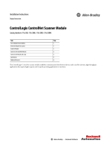
Remove the Protective Caps
1. Remove the protective caps from the fiber ports that you are going to use.
2. Save the caps for future use.
Figure 2 Protective Caps
If you plan: Then:
not to use channel(s) keep the protective caps on the channels to protect
the unit from dust.
to place the module in storage keep the protective caps on the channels to protect
the unit from dust.
to connect another module to the right
backplane connector
remove the protective backplane cap and save cap
or future use.
not to connect to the right backplane connector leave the backplane cap on.
Protective
backplane cap
DIN rail
Protective cap
The left side of the module (not shown here) also
contains a backplane connector
42599

ControlNet Modular Repeater Medium Distance Fiber Module 11
Publication 1786-IN011B-EN-P - October 2000
Choose Fiber Cable Types
Multi-fiber cables for backbone use are available with a wide range of fiber counts;
between 2 and 216 fibers. Rockwell offers the short distance (< 300 m) fiber cable
preterminated “zipcord” as a kit for use with the 1786-RPFS fiber module. You
terminate the medium and long distance (> 300 m) cable in the field.
The type of fiber cable you choose to use depends on the network environment.
Consult your installation professional to determine the best type of cable to use for
your environmental conditions. Refer to Publication CNET-IN001A-EN-P, The
ControlNet Fiber Media Planning and Installation
Guide, for details.
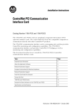
The following figure shows an example of a
multi-fiber backbone cable and two fiber interconnect
cable.
Figure 3 Cable Types
What is termination?
Termination is simply the process of attaching a connector to the ends of our fiber
cable. This is done in a similar manner as the coax BNC is terminated to the end of
a coax cable. We terminate the coax network at the two ends of the network to
prevent reflections in the system. This is not required for fiber. We recommend that
you cover unused ports with a suitable protector cap to prevent dust and other
contaminants from damaging the fiber transceiver ports. The protector cap for fiber
is equivalent to the dust cap for a ControlNet Tap drop cable.
However, for a ControlNet drop cable we also provide a 1786-TCAP for unused
taps to make them electronically transparent to the network. For the Fiber repeaters
we recommend that a simplex jumper be placed between the transmit port and
receive port of an unused channel. This is somewhat similar to the 1786-TCAP for
the coax. See Figure 2 on page 10.
30689-M
multi-fiber
backbone cable
zipcord
AB PLCs

12 ControlNet Modular Repeater Medium Distance Fiber Module
Publication 1786-IN011B-EN-P - October 2000
Specifications for 1786-RPFM Fiber Optic Cable
The quality of the fiber cable determines the distance you can achieve. Consult
your local distributor for attenuation specifications prior to purchasing your fiber
media components. The table below provides specifications for fiber optic cable:
The medium-distance fiber module (1786-RPFM) is designed for use with 62.5/
125µm multi-mode optic fiber and plastic or ceramic ST type connectors. The
wavelength used is 1300 nm.
Estimate Cable Lengths
The maximum length of a fiber cable section for the 1786-RPFM is dependent on
the quality of the fiber, number of splices, and the number of connectors. The total
attenuation for a cable section must be less than 13.3dB.
Typically cable attenuation for a wavelength of 1300nm is less than 1.5dB/km.
Item Description
Fiber Type
62.5/125
µm
Fiber Termination Type
ST
(Plastic or ceramic)
Fiber Operating Wavelength 1300nm
Optical Power Budget
13.3db
1
1
This includes all loss associated with the fiber link, including: splices, fiber attenuation, bulkhead connectors,
and the 1786–RPFM ST terminations.
IMPORTANT
Avoid splicing your cable. Connectors can cause considerable
attenuation and limit the maximum length of your system. Be
certain to check the attenuation of different cable sections
after the cable is installed.

ControlNet Modular Repeater Medium Distance Fiber Module 13
Publication 1786-IN011B-EN-P - October 2000
Connect the Fiber Cable
If you are going to use only one channel, use either Channel 1 or Channel 2.
To connect the cable for Channel 1:
1. Connect to Channel 1 Receive (RX).
a. Align the knob of the cable connector with the groove of the module
connector, and insert the connector into Channel 1 RX.
Figure 4 Connect the Fiber Cable
b. Twist the Receive connector until the bayonet lug is locked into place
2. Connect to Channel 1 Transmit (TX), repeat Step 1.
To connect the fiber cable to Channel 2:
1. Repeat the steps for Channel 1 and refer to the following figure.
30044-M
1
7
8
6
-
R
P
F
M
AB PLCs

14 ControlNet Modular Repeater Medium Distance Fiber Module
Publication 1786-IN011B-EN-P - October 2000
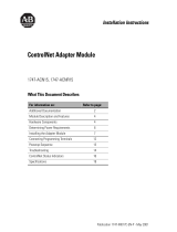
Example Topology
Figure 5 This topology is for example purposes only.
Create a new segment with a fiber repeater.
When you insert a fiber repeater into your media system, you create a new segment
or link. The same restrictions on the number of taps and cable length apply to this
new segment.
Figure 6 Basic fiber topology
N
NN
N
N
N
T
TT
T
T
T
T
T
FR
41327
coax segment
coax segment
FR
T
N
fiber segment
trunk-cable section
trunk-cable section
1786-RPA
1786-RPA
1786-RPFM
1786-RPFM
CH 1 CH2
CH 1 CH2
RX TX
RX TX
RX TX
42603
RX TX
coax segment 1
fiber repeater
adapter
fiber repeater
module
coax segment 2
tap
terminator

ControlNet Modular Repeater Medium Distance Fiber Module 15
Publication 1786-IN011B-EN-P - October 2000
Status Indicators
The figure below identifies the LEDs on the module.
Figure 7 Status Indicators:
IMPORTANT
Be certain that the fiber cable you connect to Channel 1 (RX)
on one 1786-RPFM repeater to Channel 1 (TX) on the other
1786-RPFM repeater. You can use Channel 1 or Channel 2 on
either module.
Status Indicator (LEDs) Probable Cause
Off Repeater not connected to power supply
Green Repeater is running without errors. The received data frames
are within specification for bit width distortion.
Flashing Green/Off No data activity on network.
Channel 2 LED
Channel 1 LED
42600
AB PLCs

16 ControlNet Modular Repeater Medium Distance Fiber Module
Publication 1786-IN011B-EN-P - October 2000
Related Publications
The table below lists publications that you may want to refer to for additional
information:
Mounting Dimensions
Figure 8 Mounting Dimensions
Publication Publication Number
Industrial Automation Wiring and Grounding
Guidelines
1770-4.1
ControlNet Fiber Media Planning and
Installation Manual
CNET-IN001A-EN-P
ControlNet Coax Tap Installation Instructions 1786-5.7
ControlNet COAX Media Planning and
Installation Manual
CNET-IN002A-EN-P
ControlNet Cable System Component List AG-2.2
4.44 in.
(111 mm)
2.76 in.
(69 mm)
4.048 in.
(101.2 mm)
3.6 in.
(90 mm)
4.0 in.
(100 mm)
42601

ControlNet Modular Repeater Medium Distance Fiber Module 17
Publication 1786-IN011B-EN-P - October 2000
Specifications
Specification Range
Communication Rate 5M bits/s
Operation Voltage
Class 2 operational power is provided from 1786-RPA at 5 V dc
(2)
Backplane Power Requirements 400 mA maximum
Indicators Channel 1 Status - Green
Channel 2 Status - Green
Environmental Conditions This product must be mounted within a suitable system enclosure
to prevent personal injury resulting from accessibility to live parts.
The interior of this enclosure must be accessible only by the use of
a tool.
OperatingTemperature
0 to 60
o
C (32 to 125
o
F)
Storage Temperature
-40 to 85
o
C (-40 to 185
o
F)
Pollution This industrial control equipment is intended to operate in a
Pollution Degree 2 environment, in overvoltage category II
applications, (as defined in IEC publication 664A) at altitudes up to
2000 meters without derating.
Relative Humidity 5 to 95% non-condensing
Shock Operating
Non-operating
30 g peak acceleration, 11(
± 1)ms pulse width
50 g peak acceleration, 11(
± 1)ms pulse width
Vibration Tested 5 g @ 10-500Hz per IEC 68-2-6
AB PLCs

18 ControlNet Modular Repeater Medium Distance Fiber Module
Publication 1786-IN011B-EN-P - October 2000
Fiber Type 62.5/125 micron
Fiber TerminationTypeST
(plastic or ceramic)
Fiber Operating Wavelength 1300 nm
Optical Power Budget 13.3 dB
(1)
LED Light Output
2
<5 mW/mm
Agency Certification
(when product or package marked)
1
This includes all loss associated with the fiber link, including: splices, fiber attenuation, bulkhead
connectors, and the ST terminations.
2
Power to operate this equipment must be supplied from a source compliant with "Class 2" as defined in the
National Electrical Code ANSI/NFPA 70, or the Canadian Electrical Code - Part 1, C22.1.
(1)
(2)
Specification Range
Listed Industrial Control Equipment
N223
Certified Process Control Equipment
Certified Class 1, Division 2, Groups A, B, C, D
Approved Class 1, Division 2, Groups A, B, C, D
Marked for all applicable acts
Marked for all applicable directives

ControlNet Modular Repeater Medium Distance Fiber Module 19
Publication 1786-IN011B-EN-P - October 2000
Hazardous Location Approval
The following information applies when operating
this equipment in hazardous locations:
Products marked “CL I, DIV 2, GP A, B, C, D” are suitable for use in Class I
Division 2 Groups A, B, C, D, Hazardous Locations and nonhazardous locations
only. Each product is supplied with markings on the rating nameplate indicating
the hazardous location temperature code. When combining products within a
system, the most adverse temperature code (lowest “T” number) may be used to
help determine the overall temperature code of the system. Combinations of
equipment in your system are subject to investigation by the local authority that
has jurisdiction at the time of installation.
EXPLOSION HAZARD –
• Do not disconnect equipment unless power has been removed or the area is
known to be nonhazardous.
• Do not disconnect connections to this equipment unless power has been removed
or the area is known to be nonhazardous. Secure any external connections that
mate to this equipment by using screws, sliding latches, threaded connectors, or
other means provided with this product.
• Substitution of components may impair suitability for Class I, Division 2.
• If this product contains batteries, they must only be changed in an area known to
be nonhazardous.
Informations sur l’utilisation de cet équipement
en environnements dangereux:
Les produits marqués « CL I, DIV 2, GP A, B, C, D » ne conviennent qu’à une
utilisation en environnements de Classe I Division 2 Groupes A, B, C, D
dangereux et non dangereux. Chaque produit est livré avec des marquages sur sa
plaque d’identification qui indiquent le code de température pour les
environnements dangereux. Lorsque plusieurs produits sont combinés dans un
système, le code de température le plus défavorable (code de température le plus
faible) peut être utilisé pour déterminer le code de température global du
système. Les combinaisons d’équipements dans le système sont sujettes à
inspection par les autorités locales qualifiées au moment de l’installation.
RISQUE D’EXPLOSION –
• Couper le courant ou s’assurer que l’environnement est classé non dangereux
avant de débrancher l'équipement.
• Couper le courant ou s'assurer que l’environnement est classé non dangereux
avant de débrancher les connecteurs. Fixer tous les connecteurs externes reliés à
cet équipement à l'aide de vis, loquets coulissants, connecteurs filetés ou autres
moyens fournis avec ce produit.
• La substitution de composants peut rendre cet équipement inadapté à une
utilisation en environnement de Classe 1, Division 2.
• S’assurer que l’environnement est classé non dangereux avant de changer les
piles.
AB PLCs

Publication 1786-IN011B-EN-P - October 2000 PN 957400-85
Supersedes 1786-5.11 - February 1998 © 2000 Rockwell International Corporation. Printed in the U.S.A.
Notes:
-
 1
1
-
 2
2
-
 3
3
-
 4
4
-
 5
5
-
 6
6
-
 7
7
-
 8
8
-
 9
9
-
 10
10
-
 11
11
-
 12
12
-
 13
13
-
 14
14
-
 15
15
-
 16
16
-
 17
17
-
 18
18
-
 19
19
-
 20
20


Allen-Bradley ControlNet 1786-RPFM Installation Instructions Manual
- Taper
- Installation Instructions Manual
dans d''autres langues
- English: Allen-Bradley ControlNet 1786-RPFM
Documents connexes
-
 Allen-Bradley ControlNet 1786-RPFM Installation Instructions Manual
-
 Allen-Bradley ControlNet 1786-RPFM Installation Instructions Manual
-
 Allen-Bradley ControlNet 1786-RPFS Installation Instructions Manual
-
 Allen-Bradley ControlNet 1747-SCNR Installation Instructions Manual
-
 Allen-Bradley ControlNet Coax Tap 1786-TPR Installation Instructions Manual
-
 Allen-Bradley ControlNet 1786-RPCD Installation Instructions Manual
-
 Allen-Bradley ControlLogix ControlNet Scanner Module Installation Instructions Manual
-
 Allen-Bradley ControlNet PCI 1784-PCICS Installation Instructions Manual
-
 Allen-Bradley ControlNet 1747-ACNR15 Installation Instructions Manual
-
 Allen-Bradley ControlNet-to-DeviceNet 1788-CN2DN Installation Instructions Manual