Rockwell Automation Allen-Bradley 6200T-NAK Installation Instructions Manual
- Taper
- Installation Instructions Manual

Installation Instructions
Original Instructions
VersaView 5000 Thin Clients, Industrial
Computers, and Accessories for Hazardous
Locations
Catalog Numbers
6200P-NS3A1, 6200P-NS3A1K, 6200P-NS3B1, 6200P-NS3B1K, 6200P-NS3C1,
6200P-NS3C1K, 6200P-NS3C6, 6200T-NA, 6200T-NAK, 6200V-BXDIN, 6200V-BXLGCY,
6200V-BXMACH, 6200V-BXVESA, 6200V-BXWALL, 6200V-DCCONN, 6200V-DPCBL2M,
6200V-DPDVI2, 6200V-DPHDMI4K, 6200V-DPVGA2, 6200V-DVICBL2M, 6200V-PLUGS,
6200V-USBCBL2M, and 6200V-VGACBL2M
Topic Page
Installation Precautions 2
Hazardous Locations 3
Hot Surfaces 4
Restricted Access Location 4
Environnements dangereux 5
VersaView 5000 Thin Client and Industrial Computer Options 6
Operating Systems 7
Before You Begin 8
Parts List 8
Installation Guidelines 8
Mounting Clearance Requirements 9
Dimensions 10
Tools for Installation 11
Install the VersaView 5000 Device in a Hazardous Location 11
Hardware Features 12
Connect Power 12
Install Accessories for Hazardous Locations 14
Ship or Transport VersaView 5000 Devices for Hazardous Locations 24
Technical Specifications 25
Additional Resources 27

2 Rockwell Automation Publication 6200-IN001A-EN-P - October 2019
VersaView 5000 Thin Clients, Industrial Computers, and Accessories for Hazardous Locations
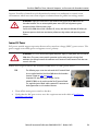
Installation Precautions
Read and follow these precautions before you install an Allen-Bradley® VersaView® 5000 device
for hazardous locations.
Environment and Enclosure Information
European Union Directive
VersaView 5000 devices for hazardous locations meet the European Union Directive
requirements when installed within the European Union or EEA regions and have the CE
marking. A copy of the
declaration of the conformity is available at the Rockwell Automation®
Product Certifications website
.
ATTENTION: This equipment is intended for use in a Pollution Degree 2 industrial environment, in
overvoltage Category II applications (as defined in EN 60664-1), at altitudes up to 2000 m
(6561 ft) without derating.
This equipment is UL Listed, and considered Group 1, Class A industrial equipment according to
EN/CISPR 32. Without appropriate precautions, there can be potential difficulties with
electromagnetic compatibility in other environments due to conducted and radiated disturbance.
All VersaView integrated display thin clients and industrial computers are shipped with a gasketed
bezel to meet specified NEMA, UL Type, and IEC IP ratings only when mounted in a panel or
enclosure with an equivalent rating.
This equipment is supplied as an open type equipment. To meet some regulatory requirements,
the equipment must be mounted in an enclosure that is suitably designed for environmental
conditions that can be present and appropriately designed to help prevent personal injury
resulting from accessibility to live parts. The interior of the enclosure must be accessible only by
using a tool.
In addition to this publication, see the following:
•Publication 1770-4.1
, Industrial Automation Wiring and Grounding Guidelines, for more
installation requirements
• NEMA 250 and EN 60529, as applicable, for explanations of the degrees of protection that are
provided by enclosures
ATTENTION: This equipment is intended to operate in an industrial or control room environment,
which uses some form of power isolation from the public low-voltage mains.
To comply with EN 55024 and EN 55032, all cables, except for the Ethernet cables, must be used
indoors. These cables cannot exit the building at any point and cannot directly connect to cables
outside the building. All I/O cables, except for the Ethernet cables and serial port (COM) cables,
must be less than 3 m (9.842 ft).

Rockwell Automation Publication 6200-IN001A-EN-P - October 2019 3
VersaView 5000 Thin Clients, Industrial Computers, and Accessories for Hazardous Locations
To comply with EN 55024 and EN 55032, use the following cable types.
Hazardous Locations
VersaView 5000 devices for hazardous locations are suitable for these location categories.
Cable Type Required Attribute Cable Type Required Attribute
LAN
Shielded
Line out
Unshielded
USB Line in
Serial RS-232 Microphone
DVI DC power
DisplayPort
Mini-DisplayPort
HDMI
VGA
Cat. Nos.
(1)
(1) Conditions for Safe Use
The following applies to VersaView 5000 thin client and industrial computers for hazardous locations:
• The equipment shall only be used in an area of not more than Pollution Degree 2, as defined in EN 60664-1.
• The equipment shall be installed in a tool-only accessible enclosure that provides a degree of protection not less
than IP54 in accordance with EN 60079-0.
• Transient protection shall be provided that is set at a level not exceeding 140% of the peak rated voltage value at
the supply terminals to the equipment.
• The internal enclosure ambient temperature range is -20…+60 °C (-4…+140 °F).
Region Rating Temperature Range
6200P-NS3A1,
6200P-NS3A1K,
6200P-NS3B1,
6200P-NS3B1K,
6200P-NS3C1,
6200P-NS3C1K,
6200P-NS3C6,
6200T-NA,
6200T-NAK
United States Class I Division 2, Groups A, B, C, D T4
-20 °C ≤ T
a
≤ +60 °C
(2)
(-4 °F ≤ T
a
≤ +140 °F)
(2) These ThinManager thin client and industrial computers for hazardous locations are required to be mounted in a
restricted access location.
Class I Zone 2, IIC, T4
Canada Class I Division 2, Groups A, B, C, D T4
Class I Zone 2, IIC, T4
Europe (ATEX) II 3 G, Ex ec IIC T4 Gc,
DEMKO 19 ATEX 2252 X

4 Rockwell Automation Publication 6200-IN001A-EN-P - October 2019
VersaView 5000 Thin Clients, Industrial Computers, and Accessories for Hazardous Locations
The following statement applies to applications in which the VersaView 5000 device is used in a
hazardous location.
Hot Surfaces
Restricted Access Location
Verify that restricted access locations meet these conditions for the VersaView 5000 devices for
hazardous locations:
• Access is gained only by service personnel or by users who have been instructed on the
reasons for restrictions to a location and about any precautions to be taken.
• Access is by using a tool, a lock and key, or other means of security controlled by the
authority responsible for the location.
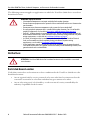
WARNING: Explosion Hazard
• Substitution of components can impair suitability for hazardous locations.
• Do not disconnect equipment unless power has been switched off and the area is known to be
non-hazardous.
• Do not connect or disconnect components unless power has been switched off.
• Use only peripheral equipment that is suitable for hazardous locations. For a list of suitable
peripheral equipment, see the table in Accessories and Replacement Parts
on page 6.
•
In the U.S., all wiring must be in accordance with Class I, Division 2 wiring methods of Article 501
of the National Electrical Code, and in accordance with the authority having jurisdiction.
For power
wiring requirements, see the table in Installation Guidelines on page 8.
• In Canada, all wiring must be in accordance with Section 18-1J2 of the Canadian Electrical
Code, and in accordance with the authority having jurisdiction. For power wiring
requirements, see the table in Installation Guidelines
on page 8.
• In final applications, properly connect these devices to ground by using the ground terminal
screw on the device chassis, the ground screw on the factory-installed mounting bracket, or the
ground terminal on the terminal block.
ATTENTION: VersaView 5000 devices for hazardous locations must be installed in a restricted
access location.

Rockwell Automation Publication 6200-IN001A-EN-P - October 2019 5
VersaView 5000 Thin Clients, Industrial Computers, and Accessories for Hazardous Locations
Environnements dangereux
Cet équipement peut être utilisé dans les environnements suivants :
• Classe I, Division 2, Groupes A, B, C et D .
•non dangereux.
La mise en garde suivante s’applique à une utilisation en environnement dangereux.
Les ordinateurs ont un code de température T4 (135°C) lorsqu’ils fonctionnent dans les
températures ambiantes maximales. Voir également le graphique Directives d’installationen
page
8 de ce document.
N’installez pas l’ordinateur dans des environnements atmosphériques explosifs (par ex. du gaz)
dont la température d’inflammabilité est inférieure à 135°C.
ATTENTION: This page is a French translation of portions of the Hazardous Locations section to
comply with certification agency requirements.
ATTENTION: Danger d'explosion
• La substitution de composants peut rendre cet équipement impropre à une utilisation en
environnement dangereux.
• Ne pas déconnecter l’équipement sans s’être assuré que l’alimentation est coupée et que
l’environnement est classé non dangereux.
• L’équipement périphérique doit être adapté à l’environnement dans lequel il est utilisé. Pour
une liste d'équipements périphériques appropriés, voir le tableau dans Accessoires et pièces
de rechange à la page 6.
• L’ensemble du câblage doit être conforme à la réglementation en vigueur dans le pays où cet
équipement est installé. Pour les exigences de câblage de puissance, voir le tableau dans
Lignes directrices sur l'installation à la page 8
.
• Tout équipement utilisé en environnement dangereux doit être monté dans une armoire
fournissant une protection adaptée aux conditions d'utilisation ambiantes et suffisante pour
éviter toute blessure corporelle pouvant résulter d'un contact direct avec des composants
sous tension.
• Dans les applications finales, connectez correctement ces appareils au sol à l'aide de la vis
terminale sur le plancher du châssis de l'appareil ou du support de montage installé en usine.

6 Rockwell Automation Publication 6200-IN001A-EN-P - October 2019
VersaView 5000 Thin Clients, Industrial Computers, and Accessories for Hazardous Locations
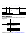
VersaView 5000 Thin Client and Industrial Computer Options
This table summarizes the options that are available for VersaView 5000 devices for hazardous
locations. A comparative summary of features is in Technical Specifications on page 25.
Accessories and Replacement Parts
The following table summarizes the accessories that are available for VersaView 5000 devices for
hazardous locations.
To install many of these accessories, see Install Accessories for Hazardous Locations
on page 14.
Cat. No.
NDM
Model
MLC SSD
Storage Size
DC
Power I/O Ports
Microsoft® Windows® OS
(64 bit)
6200P-NS3A1,
6200P-NS3A1K
Industrial
Computer
128 GB
12
…24V
•1 x USB 3.0
Type A port
•2 x USB 2.0
Type A ports
•1 x RS-232, DB9
port
•2 x Ethernet
RJ45 LAN ports,
1 Gb each
7 Professional SP1
6200P-NS3B1,
6200P-NS3B1K
Embedded Standard 7
6200P-NS3C1,
6200P-NS3C1K
10 IoT Enterprise
6200P-NS3C6 FactoryTalk® Analytics™
6200T-NA,
6200T-NAK
Thin Client — —
(1)
(1) Cat. Nos. 6200T-NA and 6200T-NAK are thin client devices for use with ThinManager® software.
Category Cat. No. Description
Mounting hardware 6200V-BXDIN DIN rail mounting kit
6200V-BXLGCY Legacy mounting plate
6200V-BXMACH Machine mounting bracket kit
6200V-BXVESA VESA mounting plate
6200V-BXWALL Bookshelf mounting plate
Cables, adapters, and
I/O accessories
6200V-DPCBL2M DisplayPort to DisplayPort cable, 2 m (6.5 ft) long
6200V-DPDVI2 DisplayPort to DVI-D active adapter
6200V-DPHDMI4K DisplayPort to HDMI active adapter
6200V-DPVGA2 DisplayPort to VGA active adapter
6200V-DVICBL2M DVI-D to DVI-D cable, 2 m (6.5 ft) long
6200V-PLUGS Protective I/O port dust caps
6200V-USBCBL2M USB touch screen cable, 2 m (6.5 ft) long
6200V-VGACBL2M VGA to VGA cable, 2 m (6.5 ft) long
Power connection 6200V-DCCONN DC power mating connector housing kit

Rockwell Automation Publication 6200-IN001A-EN-P - October 2019 7
VersaView 5000 Thin Clients, Industrial Computers, and Accessories for Hazardous Locations
Protective I/O Port Dust Caps (Cat. No. 6200V-PLUGS)
Protective I/O port dust caps are for hazardous locations where airborne chemicals or other
particulates can damage exposed I/O ports and later affect their reliability. An ordered kit
supplies dust caps for each I/O port as detailed in Figure 3 on page 12.
The four VersaView 5000 models with conformal coating (Cat. Nos. 6200P-NS3A1K,
6200P-NS3B1K, 6200P-NS3C1K, and 6200T-NAK) are shipped with these protective I/O
dust caps installed.
Operating Systems
For a list of available Microsoft-licensed 64-bit operating systems, see the table in Ve r s aV i e w
5000 Thin Client and Industrial Computer Options on page 6.
No operating system updates have been applied to the factory image beyond any listed service
packs.
To obtain a copy of a factory system image, access the Rockwell Automation® Product
Compatibility and Download Center (PCDC) at
https://compatibility.rockwellautomation.com/Pages/home.aspx
.
ARC FLASH HAZARD: Do not connect or disconnect any accessories to VersaView 5000 devices for
hazardous locations unless power has been switched off and the area is known to be
non-hazardous.
Before power is switched on, verify that any adapter, cable, or power connection accessory is fully
inserted in its port. For adapter and cable accessories, verify that latches are engaged, and any
screws are fully engaged and tightened.
Failure to do so could result in an electric arc that can cause an explosion in a hazardous location.

8 Rockwell Automation Publication 6200-IN001A-EN-P - October 2019
VersaView 5000 Thin Clients, Industrial Computers, and Accessories for Hazardous Locations
Before You Begin
Before you unpack the VersaView 5000 device for hazardous locations, inspect the shipping
carton for damage. If damage is visible, immediately contact the shipper and request assistance.
Otherwise, continue to unpack.
Keep the original packing material in case you must return the VersaView 5000 device for repair
or transport it to another location. If returned for service, use any inner and outer packing
cartons to provide adequate protection.
Parts List
VersaView 5000 devices for hazardous locations ship with the following items.
Installation Guidelines
Follow these guidelines to make sure that your VersaView 5000 device for hazardous locations
provides service with excellent reliability:
• The installation site must have sufficient power.
• Verify that the DC power wires meet these requirements:
Item Description
Hardware • DC terminal block
• Four rubber mount pads
(1)
(1) The supplied pads cannot be used as a mounting method in hazardous locations.
Documents • This publication
ATTENTION: For applications with an AC power source, the shipped AC-to-DC power
adapter must be plugged into a grounded outlet to maintain an electrically safe
installation.
An AC power supply cannot be used in a hazardous location.
Attribute Requirement
Wire material Stranded copper
Wire gauge
• To connect to DC terminal block
• To connect to earth ground
•0.326…3.31 mm
2
(22…12 AWG)
•1.5 mm
2
(16 AWG) or larger
Wire temperature rating, min 72° C (162° F)
Torque values
• To connect wires to DC terminal block
• To connect to earth ground
(1)
(1) On either computer chassis or factory-installed bookshelf mounting bracket.
• 0.22…0.25 N•m (1.95…2.21 lb•in)
• 3.1 N•m (2.29 lb•in)

Rockwell Automation Publication 6200-IN001A-EN-P - October 2019 9
VersaView 5000 Thin Clients, Industrial Computers, and Accessories for Hazardous Locations
• In dry environments, static charges can build up easily. Proper grounding helps to reduce
static discharges, which can cause shock and damage electronic components.
•The ambient air temperature must not exceed the maximum operating temperature of
60 °C (140 °F).
• The relative humidity of the ambient air must not exceed 95% @ 40 °C (104 °F), and
must avoid condensation.
• Do not remove the mounting plate on a VersaView 5000 device for hazardous locations
unless you replace it with another mounting plate.
Enclosure Guidelines
• The enclosure must allow sufficient space around air inlets and outlets to provide the
circulation necessary for cooling. For further information, see Mounting Clearance
Requirements. Never allow air passages to become obstructed.
• Hot air rises. The temperature at the top of the enclosure is often higher than the
temperature in other parts of the enclosure, especially if air is not circulating.
• Consider a user-supplied fan, heat exchanger, or air conditioner for heat generated by
other devices in the enclosure. The acceptable temperature range for these VersaView
5000 devices for hazardous locations is -20…+60 °C (-4…+140 °F).
Mounting Clearance Requirements
To help prevent overheating and to provide access to the I/O ports for cable connections, leave at
least 5 cm (2 in.) of free space around the VersaView 5000 devices for hazardous locations.
Do not obstruct the air intake, exhaust openings, or cooling fins of the cover.
IMPORTANT In hazardous locations, VersaView 5000 devices must be rated for the environment
in which they are to be used.
IMPORTANT VersaView 5000 devices for hazardous locations generate heat. Therefore, provide adequate
ventilation or other cooling methods to lower the temperature within an enclosure if the
following is likely:
• The minimum space clearance of 5 cm (2 in.) is used around the VersaView 5000 device.
• The enclosure can exceed the rated maximum temperature of 60 °C (140 °F) for the
VersaView 5000 device.

10 Rockwell Automation Publication 6200-IN001A-EN-P - October 2019
VersaView 5000 Thin Clients, Industrial Computers, and Accessories for Hazardous Locations
Dimensions
Review the following dimensions to estimate the clearance that is necessary for installation.
Dimensions are given in mm (in.).
Figure 1 - Dimensions for VersaView 5000 Devices for Hazardous Locations
210 (8.27)
140 (5.51)
63 (2.48)
Without the Factory-installed Bookshelf Mounting Plate
With the Factory-installed Bookshelf Mounting Plate
240 (9.45)
4 x Ø11
(0.43)
4 x Ø5.5
(0.22)
266 (10.47)
32
(1.26)
Ground
Screw
IMPORTANT The supplied rubber mount pads cannot be used as a mounting method in hazardous
locations.

Rockwell Automation Publication 6200-IN001A-EN-P - October 2019 11
VersaView 5000 Thin Clients, Industrial Computers, and Accessories for Hazardous Locations
Tools for Installation
You need the following tools to install the VersaView 5000 devices for hazardous locations:
• #2 cross-head screwdriver
• Drill motor and drill bit (for wall, machine, and table mounting)
• T10 Torx key or screwdriver (to install optional brackets)
• Anti-static wrist strap
Install the VersaView 5000 Device in a Hazardous Location
VersaView 5000 devices for hazardous locations ship with a factory-installed mounting plate for
wall mounting. Instructions for other available mounting plates and mounting options are
detailed in Install Accessories for Hazardous Locations
on page 14.
Follow these steps to mount a VersaView 5000 device for hazardous locations.
1. Verify that the power is disconnected.
2. Depending on your application, drill holes to accommodate customer-supplied M5 pan
head screws.
See Figure 1 on page 10
for mounting hole locations and dimensions.
3. Mount the VersaView 5000 device by using four customer-supplied M5 pan head screws.
Tighten to a torque that is appropriate for the screw quality and mounted surface
material.
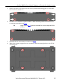
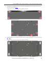
Figure 2 - Acceptable and Unacceptable Mounting Positions
IMPORTANT Certain mounting restrictions apply. See Figure 2 for details.
NOTE: The VersaView device can also be installed in
this position with I/O connections at the top.
IMPORTANT: Do not mount the VersaView device
in any position that restricts air ow
over the cooling ns.
Acceptable Mounting Positions
Unacceptable Mounting
Position

12 Rockwell Automation Publication 6200-IN001A-EN-P - October 2019
VersaView 5000 Thin Clients, Industrial Computers, and Accessories for Hazardous Locations
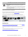
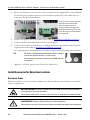
Hardware Features
This section shows the hardware features of VersaView 5000 devices for hazardous locations.
Figure 3 - Hardware Features of VersaView 5000 Devices for Hazardous Locations
Connect Power
VersaView 5000 devices for hazardous locations are factory shipped to be connected to a
12…24V DC power source.
Item Component Item Component
1 12…24V DC power input connection 7 Power light-emitting diode (LED)
2 2 x Ethernet LAN port 8 SSD LED
3 USB 3.0 port 9 Power button
4 2 x USB 2.0 port 10 VGA port
5 Serial COM port, RS-232 11 Ground stud
6DisplayPort
(1)
(1) Audio output/line out supported.
ATTENTION: When you connect power to the VersaView 5000 device for hazardous locations for
the first time, these actions occur:
• The default UEFI setting automatically starts the VersaView 5000 device after it is plugged into
a power source.
• For VersaView 5000 devices with a Windows operating system (OS), you must read and accept
an End User Setup procedure.
Do not disconnect power from the system until after the Windows Setup procedure is
completed. If power is disconnected during this procedure, it can result in a corrupted system
image.
1
2
3
4
5
6
10
9
7
8
11

Rockwell Automation Publication 6200-IN001A-EN-P - October 2019 13
VersaView 5000 Thin Clients, Industrial Computers, and Accessories for Hazardous Locations
Operate VersaView 5000 devices for hazardous locations in an industrial or control room
environment, which uses some form of power isolation from the public low-voltage mains.
Connect DC Power
DC power models support operation from a safety extra low voltage (SELV) power source. The
power supply is internally protected against reverse polarity.
Follow these steps to connect the VersaView 5000 device to a DC power source.
1. Turn off the main power switch or breaker.
2. Verify that the DC power wires meet the requirements in the table in Installation
Guidelines on page 8.
ATTENTION: Supply the circuit with its own disconnect for all VersaView 5000 devices for
hazardous locations. Use an uninterruptible power source (UPS) to help protect against
unexpected power failure or power surges.
For VersaView 5000 devices with a Windows OS, always shut down the Windows OS before you
disconnect power to the device to minimize performance degradation and operating system
failures.
ATTENTION: Use a SELV isolated and ungrounded power supply as input power to the VersaView
5000 device. This power source provides protection so that under normal and single fault
conditions, the voltage between the conductors and Functional Earth/Protective Earth does not
exceed a safe value.
TIP The following steps are to wire and attach the DC terminal block
that is supplied with the VersaView 5000 device for hazardous
locations (shown in step 3
on page 14).
An optional DC connector shown at right, Cat. No.
6200V-DCCONN, can be used instead of the DC terminal block.
The supplied terminal block and the optional DC connector are
both approved for use in hazardous locations.

14 Rockwell Automation Publication 6200-IN001A-EN-P - October 2019
VersaView 5000 Thin Clients, Industrial Computers, and Accessories for Hazardous Locations
3. Insert each DC power wire into the correct terminal on the supplied DC terminal block.
See the DC power input connector on the VersaView 5000 device for which wires to
connect to the DC terminal block.
4. Torque each power wire to the values in the table in Installation Guidelines
on page 8.
5. Connect the DC terminal block to the DC power input.
6. Connect the VersaView 5000 device to earth ground with a ground wire that meets the
requirements in the table in Installation Guidelines
on page 8.
Use a ground wire with an insulation color that is approved by local inspection authority.
7. Apply 12…24V DC power to the VersaView 5000 device.
Install Accessories for Hazardous Locations
Disconnect Power
Disconnect all power to the VersaView 5000 device for hazardous location before you install or
remove components.
TIP The factory-installed bookshelf mounting bracket has a ground
screw on one end of the bracket, as shown at right.
Use this ground screw to connect the VersaView 5000 device to
earth ground.
ARC FLASH HAZARD: Disconnect all power to VersaView 5000 devices for hazardous locations
and verify that the area is non-hazardous.
Failure to do so could result in an electric arc that can cause an explosion in a hazardous location.
SHOCK HAZARD: Disconnect all power before you remove components.
Failure to do so can result in severe electrical shock to an individual or damage to the equipment.
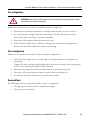
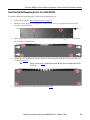
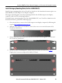
The photo on left is the DC power input
connector on the VersaView 5000
devices for hazardous locations.
The photo on right is the supplied DC
terminal block installed in the same DC
power input connector (shown without
wires connected).

Rockwell Automation Publication 6200-IN001A-EN-P - October 2019 15
VersaView 5000 Thin Clients, Industrial Computers, and Accessories for Hazardous Locations
Pre-configuration
Follow these steps before you remove or install a hardware component.
1. Shut down the VersaView 5000 device and all peripherals that are connected to it.
2. To avoid exposure to high energy levels, disconnect all cables from power outlets.
If necessary, label each cable to expedite reassembly.
3. Disconnect all peripheral cables from the I/O ports.
4. If the VersaView 5000 device is table or wall mounted, loosen the mounting screws.
Remove the VersaView 5000 device from its mounting.
Post-configuration
Follow these steps after you install or replace a hardware component.
1. If the VersaView 5000 device was wall, table, or machine mounted, reinstall it to its
mounting.
Tighten the four customer-supplied M5 pan head screws to a torque that is appropriate
for the screw quality and mounted surface material.
2. Reinstall any peripherals and system cables that were previously removed.
3. Reconnect all external cables and power to the VersaView 5000 device.
4. To start the VersaView 5000 device, press the power switch.
Required Tools
The following tools are required to install or replace a component:
• The appropriate tools for wall or machine mounting
• Torx 10 key or screwdriver
ATTENTION: Make sure to read and understand all installation and removal procedures before
you configure any hardware component.

16 Rockwell Automation Publication 6200-IN001A-EN-P - October 2019
VersaView 5000 Thin Clients, Industrial Computers, and Accessories for Hazardous Locations
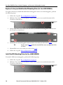
Replace a Factory-installed Bookshelf Mounting Plate (Cat. No. 6200V-BXWALL)
To replace the factory-installed bookshelf mounting plate with a new mounting plate, perform
the following steps.
1. Follow the steps for Pre-configuration
on page 15.
2. With the Torx 10 key or screwdriver, remove these two screws on the bottom of the
VersaView 5000 device.
3. Remove the four screws that secure the factory-installed mounting plate to the back of
the VersaView 5000 device.
4. Install the new mounting plate with the four screws that you removed in step 3
.
5. Reinstall the two screws that you removed in step 2.
6. Follow the steps for Post-configuration
on page 15.
Install the VESA Mounting Plate (Cat. No. 6200V-BXVESA)
To install a VESA mounting plate, perform the following steps.
1. Follow the steps for Pre-configuration
on page 15.
2. With the Torx 10 key or screwdriver, remove these two screws on the bottom of the
VersaView 5000 device.
TIP For this step and step 5, tighten the reinstalled Torx screws to a torque of 0.5 ft•lb
(0.7 N•m).

Rockwell Automation Publication 6200-IN001A-EN-P - October 2019 17
VersaView 5000 Thin Clients, Industrial Computers, and Accessories for Hazardous Locations
3. Remove the four screws that secure the factory-installed mounting plate to the back of
the VersaView 5000 device.
4. Install the new backplate supplied with the VESA mounting bracket kit with the four
screws that you removed in step 3
.
5. Reinstall the two screws that you removed in step 2.
6. With four customer-supplied screws, install the VESA mounting bracket to the VESA
mounting arm.
TIP For this step and step 5
, tighten the reinstalled Torx screws to a torque of 0.5 ft•lb
(0.7 N•m).

18 Rockwell Automation Publication 6200-IN001A-EN-P - October 2019
VersaView 5000 Thin Clients, Industrial Computers, and Accessories for Hazardous Locations
7. Remove the two screws (A) from the top of the VersaView 5000 device.
8. Remove two screws (B) from the bottom of the VersaView 5000 device.
9. Install the VersaView 5000 device to the VESA mounting bracket with the four screws
that you removed in steps 7
and 8.
Tighten the screws to a torque of 0.5 ft•lb (0.7 N•m).
10. Follow the steps for Post-configuration
on page 15.
TIP Cat. No. 6200T-NA model is used for illustrative purposes in steps 8
and 9.
A A
B B

Rockwell Automation Publication 6200-IN001A-EN-P - October 2019 19
VersaView 5000 Thin Clients, Industrial Computers, and Accessories for Hazardous Locations
Install the DIN Rail Mounting Kit (Cat. No. 6200V-BXDIN)
To install a DIN rail mounting kit, perform the following steps.
1. Follow the steps for Pre-configuration on page 15.
2. With the Torx 10 key or screwdriver, remove these two screws on the bottom of the
VersaView 5000 device.
3. Remove the four screws that secure the factory-installed mounting plate to the back of
the VersaView 5000 device.
4. Install the new backplate from the DIN rail mounting kit with the four screws that you
removed in step 3
.
5. Reinstall the two screws that you removed in step 2.
TIP For this step and step 5, tighten the reinstalled Torx screws to a torque of 0.5 ft•lb
(0.7 N•m).

20 Rockwell Automation Publication 6200-IN001A-EN-P - October 2019
VersaView 5000 Thin Clients, Industrial Computers, and Accessories for Hazardous Locations
6. Locate these two holes on the back of the VersaView 5000 device.
7. From the kit, install the DIN rail mounting bracket with the two supplied screws.
Tighten the screws to a torque of 0.5 ft•lb (0.7 N•m).
8. Install the VersaView 5000 device on a DIN rail.
9. Follow the steps for Post-configuration
on page 15.
Install the Machine Mounting Bracket Kit (Cat. No. 6200V-BXMACH)
To install the machine mounting bracket kit, perform the following steps.
1. Follow the steps for Pre-configuration
on page 15.
2. With the Torx 10 key or screwdriver, remove these two screws on the bottom of the
VersaView 5000 device.
3. Remove the four screws that secure the factory-installed mounting plate to the back of
the VersaView 5000 device.
TIP To locate these holes, verify that the newly installed backplate is at the top of the
device and the I/O ports are at the bottom.
La page est en cours de chargement...
La page est en cours de chargement...
La page est en cours de chargement...
La page est en cours de chargement...
La page est en cours de chargement...
La page est en cours de chargement...
La page est en cours de chargement...
La page est en cours de chargement...
-
 1
1
-
 2
2
-
 3
3
-
 4
4
-
 5
5
-
 6
6
-
 7
7
-
 8
8
-
 9
9
-
 10
10
-
 11
11
-
 12
12
-
 13
13
-
 14
14
-
 15
15
-
 16
16
-
 17
17
-
 18
18
-
 19
19
-
 20
20
-
 21
21
-
 22
22
-
 23
23
-
 24
24
-
 25
25
-
 26
26
-
 27
27
-
 28
28


Rockwell Automation Allen-Bradley 6200T-NAK Installation Instructions Manual
- Taper
- Installation Instructions Manual
dans d''autres langues
Documents connexes
Autres documents
-
 Allen-Bradley ControlNet 1786-RPFM Installation Instructions Manual
-
 Allen-Bradley Compact 5000 Installation Instructions Manual
-
 Allen-Bradley micrologix 1500 Installation Instructions Manual
-
 Allen-Bradley CompactLogix 1769-L30 Installation Instructions Manual
-
 Allen-Bradley ControlNet 1786-RPCD Installation Instructions Manual
-
 Allen-Bradley ControlLogix 1756-OF4 Installation Instructions Manual
-
 Allen-Bradley ControlLogix 1756-IF6CIS Installation Instructions Manual
-
 Allen-Bradley 802T Guide d'installation
-
Allen Bradley Allen-Bradley 58UHF Series RFID Short-Range Transceiver Manuel utilisateur


