IMC Networks PSE-McBasic Series Mode d'emploi
- Catégorie
- Convertisseurs de média réseau
- Taper
- Mode d'emploi

PSE-McBasic
Operation Manual
19772 Pauling• Foothill Ranch, CA 92610-2611 USA
TEL: (949) 465-3000 • FAX: (949) 465-3020
www.imcnetworks.com
© 2006 IMC Networks. All rights reserved.
The information in this document is subject to change without notice. IMC Networks assumes no responsibility for any
errors that may appear in this document. PSE-McBasic is a trademark of IMC Networks. Other brands or product
names may be trademarks and are the property of their respective companies.
Document Number 55-80927-01 A1 April 2006
If the product’s part number begins with an “8”, it is compliant with the Restriction of Hazardous
Substances (RoHS) directive.

12
Notes:
European Directive 2002/96/EC (WEEE) requires that
any equipment that bears this symbol on product or
packaging must not be disposed of with unsorted
municipal waste. This symbol indicates that the equip-
ment should be disposed of separately from regular
household waste. It is the consumer's responsibility to
dispose of this and all equipment so marked through
designated collection facilities appointed by govern-
ment or local authorities. Following these steps through
proper disposal and recycling will help prevent potential
negative consequences to the environment and human
health. For more detailed information about proper dis-
posal, please contact local authorities, waste disposal
services, or the point of purchase for this equipment.
Federal Communication Commission Radio
Frequency Interference Statement
This equipment has been tested and found to comply with the limits
for a Class B computing device, pursuant to Part 15 of the FCC Rules.
These limits are designed to provide reasonable protection against harmful
interference when the equipment is operated in a commercial environ-
ment. This equipment generates, uses and can radiate radio frequency
energy and, if not installed and used in accordance with the instruction
manual, may cause harmful interference to radio communications.
Operation of this equipment in a residential area is likely to cause harmful
interference in which the user will be required to correct the interference
at his own expense.
Any changes or modifications not expressly approved by the manufac-
turer could void the user's authority to operate the equipment.
The use of non-shielded I/O cables may not guarantee compliance with
FCC RFI limits. This digital apparatus does not exceed the Class B limits
for radio noise emission from digital apparatus set out in the Radio
Interference Regulation of the Canadian Department of Communications.
Le présent appareil numérique n’émet pas de bruits radioélectriques
dépassant les limites applicables aux appareils numériques de classe B pre-
scrites dans le Règlement sur le brouillage radioélectrique publié par le
ministère des Communications du Canada.

11
Table of Contents
About the PSE-McBasic . . . . . . . . . . . . . . . . . . . . . . . . .1
About Power over Ethernet and PSE . . . . . . . . . . . . . . . .1
About the LED Indicators . . . . . . . . . . . . . . . . . . . . . . . .2
Installing the PSE-McBasic . . . . . . . . . . . . . . . . . . . . . . .3
Configuring the PSE-McBasic . . . . . . . . . . . . . . . . . . . . .4
About FiberAlert and LinkLoss . . . . . . . . . . . . . . . . . . . .4
Auto-Negotiation and AutoCross . . . . . . . . . . . . . . . . . .7
Specifications . . . . . . . . . . . . . . . . . . . . . . . . . . . . . . . . .8
Safety Certifications . . . . . . . . . . . . . . . . . . . . . . . . . . . .8
Contact Information . . . . . . . . . . . . . . . . . . . . . . . . . . . .8
Fiber Optic Cleaning Guidelines . . . . . . . . . . . . . . . . . . .9
Electrostatic Cleaning Precautions . . . . . . . . . . . . . . . . . .9
Warranty . . . . . . . . . . . . . . . . . . . . . . . . . . . . . . . . . . . .10
Federal Communications Commission
Radio Frequency Interference Statement . . . . . . . . . . . .12
EXCEPT FOR THE EXPRESS WARRANTY SET FORTH ABOVE, IMC NET-
WORKS MAKES NO OTHER WARRANTIES, WHETHER EXPRESS OR
IMPLIED, WITH RESPECT TO THIS IMC NETWORKS PRODUCT,
INCLUDING WITHOUT LIMITATION ANY SOFTWARE ASSOCIATED OR
INCLUDED. IMC NETWORKS SHALL DISREGARD AND NOT BE
BOUND BY ANY REPRESENTATIONS OR WARRANTIES MADE BY ANY
OTHER PERSON, INCLUDING EMPLOYEES, DISTRIBUTORS, RESELLERS
OR DEALERS OF IMC NETWORKS, WHICH ARE INCONSISTENT WITH
THE WARRANTY SET FORTH ABOVE. ALL IMPLIED WARRANTIES
INCLUDING THOSE OF MERCHANTABILITY AND FITNESS FOR A PAR-
TICULAR PURPOSE ARE HEREBY LIMITED TO THE DURATION OF THE
EXPRESS WARRANTY STATED ABOVE.
Every reasonable effort has been made to ensure that IMC Networks
product manuals and promotional materials accurately describe IMC
Networks product specifications and capabilities at the time of publication.
However, because of ongoing improvements and updating of IMC
Networks products, IMC Networks cannot guarantee the accuracy of print-
ed materials after the date of publication and disclaims liability for changes,
errors or omissions.

1
10
About the PSE-McBasic
The PSE-McBasic™ functions as a fiber-to-twisted pair media converter,
as well as a 802.3af-compliant, Power Sourcing Equipment (PSE), delivering
power to a Powered Device (PD) through the UTP data cable. The PSE-
McBasic is the ideal solution when PoE powered devices, such as wireless
access points or IP cameras, need to be installed further than the
100m/300ft distance allowed by twisted-pair Ethernet cabling..
The PSE-McBasic is fully compliant with IEEE 802.3u 100 Mbps Fast
Ethernet and IEEE 802.3af Power over Ethernet standards, performing a sin-
gle conversion between 100Base-TX twisted pair and 100Base-FX multi-
mode or single-mode fiber. Single-strand fiber versions are also available.
The PSE-XT-McBasic performs the same as the PSE-McBasic but allows high-
er operating and storage temperatures.
Each PSE-McBasic includes one RJ-45 connector for the twisted pair port
and ST or SC connectors for the fiber port. The PSE-McBasic is 1U high and
includes diagnostic LEDs as well as a universal (100/240 VAC) power sup-
ply.
About Power over Ethernet and PSE
Power Over Ethernet technology allows the PSE-McBasic to function as
Power Source Equipment (PSE) by distributing an electrical current across
existing copper data cabling. If the connected unit requires power and is
802.3af compliant, the PSE detects it and supplies power. LEDs on the PSE-
McBasic indicate the amount of power being supplied to the Powered
Device (PD) as well as if the PSE-McBasic is over temperature or over cur-
rent or has an open circuit. PSE functionality is enabled by default.
NOTE
The PSE-XT-McBasic also includes an internal fan. This fan automatically
turns on when the internal temperature of the unit exceeds 45° C. The
PSE-McBasic does not require a fan.
Warranty
IMC Networks warrants to the original end-user purchaser that this prod-
uct, EXCLUSIVE OF SOFTWARE, shall be free from defects in materials and
workmanship under normal and proper use in accordance with IMC
Networks' instructions and directions for a period of six (6) years after the
original date of purchase. This warranty is subject to the limitations set forth
below.
At its option, IMC Networks will repair or replace at no charge the prod-
uct which proves to be defective within such warranty period. This limited
warranty shall not apply if the IMC Networks product has been damaged by
unreasonable use, accident, negligence, service or modification by anyone
other than an authorized IMC Networks Service Technician or by any other
causes unrelated to defective materials or workmanship. Any replaced or
repaired products or parts carry a ninety (90) day warranty or the remain-
der of the initial warranty period, whichever is longer.
To receive in-warranty service, the defective product must be received at
IMC Networks no later than the end of the warranty period. The product
must be accompanied by proof of purchase, satisfactory to IMC Networks,
denoting product serial number and purchase date, a written description of
the defect and a Return Merchandise Authorization (RMA) number issued
by IMC Networks. No products will be accepted by IMC Networks which
do not have an RMA number. For an RMA number, contact IMC Networks
at PHONE: (800) 624-1070 (in the U.S and Canada) or (949) 465-3000 or
FAX: (949) 465-3020. The end-user shall return the defective product to
IMC Networks, freight, customs and handling charges prepaid. End-user
agrees to accept all liability for loss of or damages to the returned product
during shipment. IMC Networks shall repair or replace the returned prod-
uct, at its option, and return the repaired or new product to the end-user,
freight prepaid, via method to be determined by IMC Networks.
IMC Networks shall not be liable for any costs of procurement of substi-
tute goods, loss of profits, or any incidental, consequential, and/or special
damages of any kind resulting from a breach of any applicable express or
implied warranty, breach of any obligation arising from breach of warranty,
or otherwise with respect to the manufacture and sale of any IMC Networks
product, whether or not IMC Networks has been advised of the possibility
of such loss or damage.
NOTE
Although the PSE-McBasic automatically detects Powered Devices (PDs),
and only supplies power when connected to an 802.3af-compliant PD,
set the PSE switch to OFF when connecting to a non-802.3af-compliant
device.

9
2
Fiber Optic Cleaning Guidelines
Fiber optic equipment is extremely susceptible to contamination by par-
ticles of dirt or dust which can obstruct the optics and cause performance
degradation. Good system performance requires clean optics and connec-
tor ferrules.
1) Only use fiber patch cords (or connectors) from a reputable supplier;
low-quality components can cause many hard-to-diagnose problems.
2) IMC Networks installs dust caps to ensure factory-clean optical
devices. These protective caps should not be removed until the
moment of connecting the fiber cable to the device. Assure that the
fiber is properly terminated, polished and free of any dust or dirt and
that the location is as free from dust and dirt as possible.
3) Store spare caps in a dust-free environment such as a sealed plastic
bag or box so reinstalled caps do not introduce any contamination to
the optics.
4) Reinstall the protective caps when disconnecting the fiber device.
5) To clean contaminated optics, alternate between blasting with clean,
dry, compressed air and flushing with methanol to remove particles
of dirt.
Electrostatic Discharge Precautions
Electrostatic discharge (ESD) can damage to add-in modules. Always
observe the following precautions when installing or handling an add-in
module or any board assembly.
1) Do not remove unit from its protective packaging until ready to
install it.
2) Wear an ESD wrist grounding strap before handling any module or
component. If without a wrist strap, maintain grounded contact
with the system unit throughout any procedure requiring ESD pro-
tection.
3) Hold boards by the edges only; do not touch the electronic compo-
nents or gold connectors.
4) After removal, always place the boards on a grounded, static free
surface, ESD pad or in a proper ESD bag. Do not slide the board
over any surface.
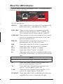
About the LED Indicators
The PSE-McBasic features four diagnostic LEDs. The diagram below
shows the location of the LEDs.
The LED functions are:
LNK/ACT Glows amber when a twisted pair link is established and
blinks when activity is detected on the UTP port.
ZERO CRNT Glows red when no device is connected to the PSE-
McBasic or when the device is NOT a valid PD. The
LED is off when the PSE-McBasic detects a valid PD.
OVER CRNT Glows red when an overcurrent condition lasts for more
than 60 ms after power up and/or when an over tem-
perature condition occurs.
PWR FAIL Glows red when an overcurrent or internal fault is
detected within the PSE-McBasic PoE circuit.
PWR Glows green when the PSE-McBasic is powered up.
AN Glows green when Auto-Negotiation is enabled.
TX LL Glows green when TX LinkLoss is enabled.
FX LL Glows green when FX LinkLoss is enabled.
FA Glows green when FiberAlert is enabled and blinks when
a FiberAlert situation occurs (i.e. the loss of one strand of
fiber).
4W Glows green when Powered Device consumes 3.84
watts to 4 watts of power (CLASS1 PD).
7W Glows green when Powered Device consumes 6.49
watts to 7 watts of power (CLASS2 PD).
15.4W Glows green when Powered Device consumes 12.95
watts to 15.4 watts of power (CLASS0 PD).
FX LNK/ACT Glows green when a link is established on the fiber port
and blinks when activity is detected on the port.
NOTE
FiberAlert will not function when single-strand fiber is connected.
WARNING
Integrated circuits and fiber optic components are extremely susceptible to elec-
trostatic discharge damage. Only qualified service technicians using tools and
techniques conforming to accepted industry practices should handle these com-
ponents.

3
8
Installing the PSE-McBasic
While the PSE-McBasic comes ready to install, all configuration changes
should be made after installation. To install the PSE-McBasic first make sure
that it is placed on a suitably flat surface. Attach the cables between the
PSE-McBasic and each device that will be interconnected. Then, plug it
into a reliable, filtered power source.
INSTALLATION TROUBLESHOOTING
To test the PSE-McBasic during installation, first test the fiber and twisted
pair connections with all troubleshooting features disabled, then enable
these features, if desired, just before final installation. This will reduce the
features’ interference with testing.
When working with units whose features cannot be disabled, both twisted
pair and fiber cables must be connected before the link LEDs will light.
To test a PSE-McBasic by itself, first verify that an appropriate fiber patch
cable is being used. Then, follow these steps:
Step 1: Connect the PSE-McBasic to the twisted pair
device with a twisted pair cable.
Step 2: Loop a single strand of fiber from the transmit port
to the receive port of the PSE-McBasic.
Step 3: Verify that both twisted pair and fiber link LEDs
light on the PSE-McBasic.
Use the appropriate twisted pair cable, and have the crossover/pass-
through switch set correctly.
If using a high powered device designed for long distance installations in a
short distance installation, an optical attenuator may be needed to prevent
data loss on a connection.
Visit www.imcnetworks.com or call IMC Networks for more information.
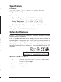
Specifications
Dimensions
1.45”H x 4.73”W x 7.30”D (3.68 cm x 12.01 cm x 18.54 cm)
Weight: 1.8 lbs (.82 kg)
Environmental
Operating Temperature: 32° to 122° F (0° to +50° C);
0° to 149° F (-20° to +65° C) for PSE-XT-McBasic
Storage Temperature: -13° to +158°F (-25° to +70°C);
0° to 185° F (-20° to +85° C) for PSE-XT-McBasic
Humidity: 5% to 90%, noncondensing, 0 – 10,000 ft. altitude
Power Consumption
AC Input Load: 100-240VAC ±10%, 50/60 Hz, 1A
Safety Certifications
UL/CUL: Listed to Safety of Information Technology Equipment, Including
Electrical Business Equipment.
CE: The products described herein comply with the Council Directive on
Electromagnetic Compatibility (89/336/EEC) and the Council Directive on
Electrical Equipment Designed for use within Certain Voltage Limits
(73/23/EEC). Certified to Safety of Information Technology Equipment,
Including Electrical Business Equipment. For further details, contact IMC
Networks.
Contact Information
Tel: (949)-465-3000; (800)-624-1070 (in U.S. and Canada)
+32-16-550880 (Europe)
Fax: (949)-465-3020
E-mail: [email protected]
Web site: www.imcnetworks.com
INSTALLATION TIP
Several versions of the PSE-McBasic support single-strand fiber operation.
Since single-strand fiber products use optics that transmit and receive on
two different wavelengths, deploy single-strand fiber products in pairs, or
connect two compatible IMC Networks single-strand fiber products. For
example, connect a PSE-McBasic, TX/SSFX-SM1310-SC (which has 1310
xmt and 1550 rcv) to a product which has 1550 xmt and 1310 rcv, e.g.
an iMcV-LIM, TX/SSFX-SM1550-SC. The two connected products must
also have the same speed and distance capabilities (i.e. both are single-
mode [20km] or both are single/PLUS [40km]).
Class 1 Laser product, Luokan 1 Laserlaite,
Laser Klasse 1, Appareil A’Laser de Classe 1

7
4
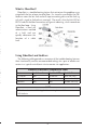
What Is Pulsing FiberAlert?
Pulsing FiberAlert provides the same function as FiberAlert but, rather
than ceasing transmission when the receiving unit goes down, Pulsing
FiberAlert sends pulses through the line so that once the receiving unit starts
to function, transmission commences. Use Pulsing FiberAlert in the follow-
ing two situations:
A) When connecting two PSE-McBasic units (or connecting a
PSE-McBasic to a McLIM TX/FX) with FiberAlert enabled.
B) When connecting one PSE-McBasic with FiberAlert enabled and
one McBasic 10/100 unit with Link Fault Detection (LFD) enabled.
Visit http://www.imcnetworks.com/adocs/support/to-features.pdf for
more information or contact IMC Networks technical support at (800) 624-
1070 (U.S./ Canada), +32-16-550880 (Europe) or via e-mail at: techsup-
Auto-Negotiation and AutoCross
The PSE-McBasic also includes Auto-Negotiation and AutoCross.
Auto-Negotiation
Auto-Negotiation, enabled by default, allows the PSE-McBasic to com-
municate at the speed and duplex settings of the device to which it is con-
nected. Therefore, if the device connected to the PSE-McBasic sends and
receives at 100Mbps, Full-Duplex, so will the PSE-McBasic. This will func-
tion within the operating parameters of the PSE-McBasic (10/100Mbps,
Half or Full Duplex).
To make the PSE-McBasic only communicate at one speed or one duplex
setting, Auto-Negotiation will need to be turned off.
AutoCross
Whether using crossover or straight-through CAT5 twisted pair cabling,
the PSE-McBasic will support both types of connections. The PSE-McBasic
includes AutoCross, a feature that automatically selects between a crossover
workstation or pass-through connection depending on the connected
device.
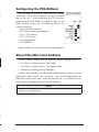
Configuring the PSE-McBasic
The PSE-McBasic features an 8 DIP switches, set after
installation. Access these through a cut-out in the bot-
tom of the unit. After configuring the DIP switches,
power cycle the PSE McBasic for the changes to take
effect. Default settings for the following features are
shown to the right.
• Pulse (Pulsing FiberAlert)
• PSE (Power Sourcing Equipment)
• TX LL (TX LinkLoss)
• FX LL (FX LinkLoss)
• Auto-Negotiation
• FA (FiberAlert)
Some switches are reserved for future development.
About FiberAlert and LinkLoss
The PSE-McBasic comes with the following troubleshooting features:
• FX LinkLoss (LinkLoss over a Fiber cable)
• TX LinkLoss (LinkLoss over a Twisted Pair cable)
• FiberAlert (including Pulsing FiberAlert)
LinkLoss and FiberAlert are advanced troubleshooting features that can
help locate "silent failures" on a network. Users should understand how
FiberAlert and LinkLoss work, and how they will act in a network environ-
ment, before attempting to install the PSE-McBasic.
NOTE
Without understanding LinkLoss and FiberAlert, the PSE-McBasic could appear
flawed or even malfunctioning.
Converter 1 Converter 2
FiberAlert Enabled FiberAlert and Pulsing FiberAlert Enabled
FiberAlert Enabled FiberAlert Disabled
INSTALLATION TIP
Enable FiberAlert and/or Pulsing FiberAlert on only ONE side of a media con-
version; enabling it on both sides will keep both transmitters off indefinitely.

5
6
About Link Integrity
During normal operation, link integrity pulses are transmitted by all
point-to-point Ethernet devices. When a PSE-McBasic receives valid link
pulses, it knows that the device to which it is connected is functioning, and
that the copper or fiber cable coming from that device is intact. The appro-
priate “LINK” LED is lit to indicate this. The PSE-McBasic also sends out
link pulses from its copper and fiber transmitters, but normally has no way
of knowing whether the cable to the other device is intact and the link puls-
es are reaching the other end. FiberAlert and LinkLoss allow this informa-
tion to be obtained from the fiber, even when physical access to a remote
device (and its link integrity LED) is not available.
What Is FX LinkLoss?
FX LinkLoss is a troubleshooting feature that allows users to detect fail-
ures over the fiber connection. When a fault occurs on the fiber segment
of a conversion, FX LinkLoss detects the fault and passes this information to
the twisted pair segment. If a PSE-McBasic is not receiving a fiber link, FX
LinkLoss disables the transmitter on the PSE-McBasic 's twisted pair port.
This results in a loss of link on the device connected to the twisted pair port.
What Is TX LinkLoss?
TX LinkLoss is a troubleshooting feature that allows users to detect fail-
ures over the twisted-pair connection. When a fault occurs on the twisted
pair segment of a conversion, TX LinkLoss detects the fault and passes this
information to the fiber segment. If a PSE-McBasic is not receiving a twist-
ed pair link, TX LinkLoss disables the transmitter on the media converter's
fiber port. This results in a loss of link on the device connected to the fiber
port.
What is FiberAlert?
FiberAlert is a troubleshooting feature that minimizes the problems asso-
ciated with the loss of one strand of fiber. If a strand is unavailable, the PSE-
McBasic notes the lost link and will stop transmitting data and the link sig-
nal until a signal or link pulse is received. The result is that the link LED on
BOTH sides of the fiber connection will go out indicating a fault somewhere
in the fiber loop. Using
FiberAlert, a local site
administrator is notified
of a fault and can
quickly determine the
location of a cable
fault.
Using FiberAlert and LinkLoss
The following table provides an overview of the troubleshooting features,
their functionality and the recommended settings for a pair of media con-
verters in a typical central/main site to remote site application:
LinkLoss/FiberAlert Comparison Table
Feature Fault Location Disabled LEDs Enable At
FX LinkLoss Fiber Twisted Pair Main Site Only
TX LinkLoss Twisted Pair Fiber Remote Site Only
FiberAlert Fiber Fiber Remote Site Only
NOTE
FiberAlert is not available/applicable on single-strand fiber versions of
PSE-McBasic.

7
4
What Is Pulsing FiberAlert?
Pulsing FiberAlert provides the same function as FiberAlert but, rather
than ceasing transmission when the receiving unit goes down, Pulsing
FiberAlert sends pulses through the line so that once the receiving unit starts
to function, transmission commences. Use Pulsing FiberAlert in the follow-
ing two situations:
A) When connecting two PSE-McBasic units (or connecting a
PSE-McBasic to a McLIM TX/FX) with FiberAlert enabled.
B) When connecting one PSE-McBasic with FiberAlert enabled and
one McBasic 10/100 unit with Link Fault Detection (LFD) enabled.
Visit http://www.imcnetworks.com/adocs/support/to-features.pdf for
more information or contact IMC Networks technical support at (800) 624-
1070 (U.S./ Canada), +32-16-550880 (Europe) or via e-mail at: techsup-
Auto-Negotiation and AutoCross
The PSE-McBasic also includes Auto-Negotiation and AutoCross.
Auto-Negotiation
Auto-Negotiation, enabled by default, allows the PSE-McBasic to com-
municate at the speed and duplex settings of the device to which it is con-
nected. Therefore, if the device connected to the PSE-McBasic sends and
receives at 100Mbps, Full-Duplex, so will the PSE-McBasic. This will func-
tion within the operating parameters of the PSE-McBasic (10/100Mbps,
Half or Full Duplex).
To make the PSE-McBasic only communicate at one speed or one duplex
setting, Auto-Negotiation will need to be turned off.
AutoCross
Whether using crossover or straight-through CAT5 twisted pair cabling,
the PSE-McBasic will support both types of connections. The PSE-McBasic
includes AutoCross, a feature that automatically selects between a crossover
workstation or pass-through connection depending on the connected
device.
Configuring the PSE-McBasic
The PSE-McBasic features an 8 DIP switches, set after
installation. Access these through a cut-out in the bot-
tom of the unit. After configuring the DIP switches,
power cycle the PSE McBasic for the changes to take
effect. Default settings for the following features are
shown to the right.
• Pulse (Pulsing FiberAlert)
• PSE (Power Sourcing Equipment)
• TX LL (TX LinkLoss)
• FX LL (FX LinkLoss)
• Auto-Negotiation
• FA (FiberAlert)
Some switches are reserved for future development.
About FiberAlert and LinkLoss
The PSE-McBasic comes with the following troubleshooting features:
• FX LinkLoss (LinkLoss over a Fiber cable)
• TX LinkLoss (LinkLoss over a Twisted Pair cable)
• FiberAlert (including Pulsing FiberAlert)
LinkLoss and FiberAlert are advanced troubleshooting features that can
help locate "silent failures" on a network. Users should understand how
FiberAlert and LinkLoss work, and how they will act in a network environ-
ment, before attempting to install the PSE-McBasic.
NOTE
Without understanding LinkLoss and FiberAlert, the PSE-McBasic could appear
flawed or even malfunctioning.
Converter 1 Converter 2
FiberAlert Enabled FiberAlert and Pulsing FiberAlert Enabled
FiberAlert Enabled FiberAlert Disabled
INSTALLATION TIP
Enable FiberAlert and/or Pulsing FiberAlert on only ONE side of a media con-
version; enabling it on both sides will keep both transmitters off indefinitely.

3
8
Installing the PSE-McBasic
While the PSE-McBasic comes ready to install, all configuration changes
should be made after installation. To install the PSE-McBasic first make sure
that it is placed on a suitably flat surface. Attach the cables between the
PSE-McBasic and each device that will be interconnected. Then, plug it
into a reliable, filtered power source.
INSTALLATION TROUBLESHOOTING
To test the PSE-McBasic during installation, first test the fiber and twisted
pair connections with all troubleshooting features disabled, then enable
these features, if desired, just before final installation. This will reduce the
features’ interference with testing.
When working with units whose features cannot be disabled, both twisted
pair and fiber cables must be connected before the link LEDs will light.
To test a PSE-McBasic by itself, first verify that an appropriate fiber patch
cable is being used. Then, follow these steps:
Step 1: Connect the PSE-McBasic to the twisted pair
device with a twisted pair cable.
Step 2: Loop a single strand of fiber from the transmit port
to the receive port of the PSE-McBasic.
Step 3: Verify that both twisted pair and fiber link LEDs
light on the PSE-McBasic.
Use the appropriate twisted pair cable, and have the crossover/pass-
through switch set correctly.
If using a high powered device designed for long distance installations in a
short distance installation, an optical attenuator may be needed to prevent
data loss on a connection.
Visit www.imcnetworks.com or call IMC Networks for more information.
Specifications
Dimensions
1.45”H x 4.73”W x 7.30”D (3.68 cm x 12.01 cm x 18.54 cm)
Weight: 1.8 lbs (.82 kg)
Environmental
Operating Temperature: 32° to 122° F (0° to +50° C);
0° to 149° F (-20° to +65° C) for PSE-XT-McBasic
Storage Temperature: -13° to +158°F (-25° to +70°C);
0° to 185° F (-20° to +85° C) for PSE-XT-McBasic
Humidity: 5% to 90%, noncondensing, 0 – 10,000 ft. altitude
Power Consumption
AC Input Load: 100-240VAC ±10%, 50/60 Hz, 1A
Safety Certifications
UL/CUL: Listed to Safety of Information Technology Equipment, Including
Electrical Business Equipment.
CE: The products described herein comply with the Council Directive on
Electromagnetic Compatibility (89/336/EEC) and the Council Directive on
Electrical Equipment Designed for use within Certain Voltage Limits
(73/23/EEC). Certified to Safety of Information Technology Equipment,
Including Electrical Business Equipment. For further details, contact IMC
Networks.
Contact Information
Tel: (949)-465-3000; (800)-624-1070 (in U.S. and Canada)
+32-16-550880 (Europe)
Fax: (949)-465-3020
E-mail: [email protected]
Web site: www.imcnetworks.com
INSTALLATION TIP
Several versions of the PSE-McBasic support single-strand fiber operation.
Since single-strand fiber products use optics that transmit and receive on
two different wavelengths, deploy single-strand fiber products in pairs, or
connect two compatible IMC Networks single-strand fiber products. For
example, connect a PSE-McBasic, TX/SSFX-SM1310-SC (which has 1310
xmt and 1550 rcv) to a product which has 1550 xmt and 1310 rcv, e.g.
an iMcV-LIM, TX/SSFX-SM1550-SC. The two connected products must
also have the same speed and distance capabilities (i.e. both are single-
mode [20km] or both are single/PLUS [40km]).
Class 1 Laser product, Luokan 1 Laserlaite,
Laser Klasse 1, Appareil A’Laser de Classe 1

9
2
Fiber Optic Cleaning Guidelines
Fiber optic equipment is extremely susceptible to contamination by par-
ticles of dirt or dust which can obstruct the optics and cause performance
degradation. Good system performance requires clean optics and connec-
tor ferrules.
1) Only use fiber patch cords (or connectors) from a reputable supplier;
low-quality components can cause many hard-to-diagnose problems.
2) IMC Networks installs dust caps to ensure factory-clean optical
devices. These protective caps should not be removed until the
moment of connecting the fiber cable to the device. Assure that the
fiber is properly terminated, polished and free of any dust or dirt and
that the location is as free from dust and dirt as possible.
3) Store spare caps in a dust-free environment such as a sealed plastic
bag or box so reinstalled caps do not introduce any contamination to
the optics.
4) Reinstall the protective caps when disconnecting the fiber device.
5) To clean contaminated optics, alternate between blasting with clean,
dry, compressed air and flushing with methanol to remove particles
of dirt.
Electrostatic Discharge Precautions
Electrostatic discharge (ESD) can damage to add-in modules. Always
observe the following precautions when installing or handling an add-in
module or any board assembly.
1) Do not remove unit from its protective packaging until ready to
install it.
2) Wear an ESD wrist grounding strap before handling any module or
component. If without a wrist strap, maintain grounded contact
with the system unit throughout any procedure requiring ESD pro-
tection.
3) Hold boards by the edges only; do not touch the electronic compo-
nents or gold connectors.
4) After removal, always place the boards on a grounded, static free
surface, ESD pad or in a proper ESD bag. Do not slide the board
over any surface.
About the LED Indicators
The PSE-McBasic features four diagnostic LEDs. The diagram below
shows the location of the LEDs.
The LED functions are:
LNK/ACT Glows amber when a twisted pair link is established and
blinks when activity is detected on the UTP port.
ZERO CRNT Glows red when no device is connected to the PSE-
McBasic or when the device is NOT a valid PD. The
LED is off when the PSE-McBasic detects a valid PD.
OVER CRNT Glows red when an overcurrent condition lasts for more
than 60 ms after power up and/or when an over tem-
perature condition occurs.
PWR FAIL Glows red when an overcurrent or internal fault is
detected within the PSE-McBasic PoE circuit.
PWR Glows green when the PSE-McBasic is powered up.
AN Glows green when Auto-Negotiation is enabled.
TX LL Glows green when TX LinkLoss is enabled.
FX LL Glows green when FX LinkLoss is enabled.
FA Glows green when FiberAlert is enabled and blinks when
a FiberAlert situation occurs (i.e. the loss of one strand of
fiber).
4W Glows green when Powered Device consumes 3.84
watts to 4 watts of power (CLASS1 PD).
7W Glows green when Powered Device consumes 6.49
watts to 7 watts of power (CLASS2 PD).
15.4W Glows green when Powered Device consumes 12.95
watts to 15.4 watts of power (CLASS0 PD).
FX LNK/ACT Glows green when a link is established on the fiber port
and blinks when activity is detected on the port.
NOTE
FiberAlert will not function when single-strand fiber is connected.
WARNING
Integrated circuits and fiber optic components are extremely susceptible to elec-
trostatic discharge damage. Only qualified service technicians using tools and
techniques conforming to accepted industry practices should handle these com-
ponents.

1
10
About the PSE-McBasic
The PSE-McBasic™ functions as a fiber-to-twisted pair media converter,
as well as a 802.3af-compliant, Power Sourcing Equipment (PSE), delivering
power to a Powered Device (PD) through the UTP data cable. The PSE-
McBasic is the ideal solution when PoE powered devices, such as wireless
access points or IP cameras, need to be installed further than the
100m/300ft distance allowed by twisted-pair Ethernet cabling..
The PSE-McBasic is fully compliant with IEEE 802.3u 100 Mbps Fast
Ethernet and IEEE 802.3af Power over Ethernet standards, performing a sin-
gle conversion between 100Base-TX twisted pair and 100Base-FX multi-
mode or single-mode fiber. Single-strand fiber versions are also available.
The PSE-XT-McBasic performs the same as the PSE-McBasic but allows high-
er operating and storage temperatures.
Each PSE-McBasic includes one RJ-45 connector for the twisted pair port
and ST or SC connectors for the fiber port. The PSE-McBasic is 1U high and
includes diagnostic LEDs as well as a universal (100/240 VAC) power sup-
ply.
About Power over Ethernet and PSE
Power Over Ethernet technology allows the PSE-McBasic to function as
Power Source Equipment (PSE) by distributing an electrical current across
existing copper data cabling. If the connected unit requires power and is
802.3af compliant, the PSE detects it and supplies power. LEDs on the PSE-
McBasic indicate the amount of power being supplied to the Powered
Device (PD) as well as if the PSE-McBasic is over temperature or over cur-
rent or has an open circuit. PSE functionality is enabled by default.
NOTE
The PSE-XT-McBasic also includes an internal fan. This fan automatically
turns on when the internal temperature of the unit exceeds 45° C. The
PSE-McBasic does not require a fan.
Warranty
IMC Networks warrants to the original end-user purchaser that this prod-
uct, EXCLUSIVE OF SOFTWARE, shall be free from defects in materials and
workmanship under normal and proper use in accordance with IMC
Networks' instructions and directions for a period of six (6) years after the
original date of purchase. This warranty is subject to the limitations set forth
below.
At its option, IMC Networks will repair or replace at no charge the prod-
uct which proves to be defective within such warranty period. This limited
warranty shall not apply if the IMC Networks product has been damaged by
unreasonable use, accident, negligence, service or modification by anyone
other than an authorized IMC Networks Service Technician or by any other
causes unrelated to defective materials or workmanship. Any replaced or
repaired products or parts carry a ninety (90) day warranty or the remain-
der of the initial warranty period, whichever is longer.
To receive in-warranty service, the defective product must be received at
IMC Networks no later than the end of the warranty period. The product
must be accompanied by proof of purchase, satisfactory to IMC Networks,
denoting product serial number and purchase date, a written description of
the defect and a Return Merchandise Authorization (RMA) number issued
by IMC Networks. No products will be accepted by IMC Networks which
do not have an RMA number. For an RMA number, contact IMC Networks
at PHONE: (800) 624-1070 (in the U.S and Canada) or (949) 465-3000 or
FAX: (949) 465-3020. The end-user shall return the defective product to
IMC Networks, freight, customs and handling charges prepaid. End-user
agrees to accept all liability for loss of or damages to the returned product
during shipment. IMC Networks shall repair or replace the returned prod-
uct, at its option, and return the repaired or new product to the end-user,
freight prepaid, via method to be determined by IMC Networks.
IMC Networks shall not be liable for any costs of procurement of substi-
tute goods, loss of profits, or any incidental, consequential, and/or special
damages of any kind resulting from a breach of any applicable express or
implied warranty, breach of any obligation arising from breach of warranty,
or otherwise with respect to the manufacture and sale of any IMC Networks
product, whether or not IMC Networks has been advised of the possibility
of such loss or damage.
NOTE
Although the PSE-McBasic automatically detects Powered Devices (PDs),
and only supplies power when connected to an 802.3af-compliant PD,
set the PSE switch to OFF when connecting to a non-802.3af-compliant
device.

11
Table of Contents
About the PSE-McBasic . . . . . . . . . . . . . . . . . . . . . . . . .1
About Power over Ethernet and PSE . . . . . . . . . . . . . . . .1
About the LED Indicators . . . . . . . . . . . . . . . . . . . . . . . .2
Installing the PSE-McBasic . . . . . . . . . . . . . . . . . . . . . . .3
Configuring the PSE-McBasic . . . . . . . . . . . . . . . . . . . . .4
About FiberAlert and LinkLoss . . . . . . . . . . . . . . . . . . . .4
Auto-Negotiation and AutoCross . . . . . . . . . . . . . . . . . .7
Specifications . . . . . . . . . . . . . . . . . . . . . . . . . . . . . . . . .8
Safety Certifications . . . . . . . . . . . . . . . . . . . . . . . . . . . .8
Contact Information . . . . . . . . . . . . . . . . . . . . . . . . . . . .8
Fiber Optic Cleaning Guidelines . . . . . . . . . . . . . . . . . . .9
Electrostatic Cleaning Precautions . . . . . . . . . . . . . . . . . .9
Warranty . . . . . . . . . . . . . . . . . . . . . . . . . . . . . . . . . . . .10
Federal Communications Commission
Radio Frequency Interference Statement . . . . . . . . . . . .12
EXCEPT FOR THE EXPRESS WARRANTY SET FORTH ABOVE, IMC NET-
WORKS MAKES NO OTHER WARRANTIES, WHETHER EXPRESS OR
IMPLIED, WITH RESPECT TO THIS IMC NETWORKS PRODUCT,
INCLUDING WITHOUT LIMITATION ANY SOFTWARE ASSOCIATED OR
INCLUDED. IMC NETWORKS SHALL DISREGARD AND NOT BE
BOUND BY ANY REPRESENTATIONS OR WARRANTIES MADE BY ANY
OTHER PERSON, INCLUDING EMPLOYEES, DISTRIBUTORS, RESELLERS
OR DEALERS OF IMC NETWORKS, WHICH ARE INCONSISTENT WITH
THE WARRANTY SET FORTH ABOVE. ALL IMPLIED WARRANTIES
INCLUDING THOSE OF MERCHANTABILITY AND FITNESS FOR A PAR-
TICULAR PURPOSE ARE HEREBY LIMITED TO THE DURATION OF THE
EXPRESS WARRANTY STATED ABOVE.
Every reasonable effort has been made to ensure that IMC Networks
product manuals and promotional materials accurately describe IMC
Networks product specifications and capabilities at the time of publication.
However, because of ongoing improvements and updating of IMC
Networks products, IMC Networks cannot guarantee the accuracy of print-
ed materials after the date of publication and disclaims liability for changes,
errors or omissions.

12
Notes:
European Directive 2002/96/EC (WEEE) requires that
any equipment that bears this symbol on product or
packaging must not be disposed of with unsorted
municipal waste. This symbol indicates that the equip-
ment should be disposed of separately from regular
household waste. It is the consumer's responsibility to
dispose of this and all equipment so marked through
designated collection facilities appointed by govern-
ment or local authorities. Following these steps through
proper disposal and recycling will help prevent potential
negative consequences to the environment and human
health. For more detailed information about proper dis-
posal, please contact local authorities, waste disposal
services, or the point of purchase for this equipment.
Federal Communication Commission Radio
Frequency Interference Statement
This equipment has been tested and found to comply with the limits
for a Class B computing device, pursuant to Part 15 of the FCC Rules.
These limits are designed to provide reasonable protection against harmful
interference when the equipment is operated in a commercial environ-
ment. This equipment generates, uses and can radiate radio frequency
energy and, if not installed and used in accordance with the instruction
manual, may cause harmful interference to radio communications.
Operation of this equipment in a residential area is likely to cause harmful
interference in which the user will be required to correct the interference
at his own expense.
Any changes or modifications not expressly approved by the manufac-
turer could void the user's authority to operate the equipment.
The use of non-shielded I/O cables may not guarantee compliance with
FCC RFI limits. This digital apparatus does not exceed the Class B limits
for radio noise emission from digital apparatus set out in the Radio
Interference Regulation of the Canadian Department of Communications.
Le présent appareil numérique n’émet pas de bruits radioélectriques
dépassant les limites applicables aux appareils numériques de classe B pre-
scrites dans le Règlement sur le brouillage radioélectrique publié par le
ministère des Communications du Canada.

PSE-McBasic
Operation Manual
19772 Pauling• Foothill Ranch, CA 92610-2611 USA
TEL: (949) 465-3000 • FAX: (949) 465-3020
www.imcnetworks.com
© 2006 IMC Networks. All rights reserved.
The information in this document is subject to change without notice. IMC Networks assumes no responsibility for any
errors that may appear in this document. PSE-McBasic is a trademark of IMC Networks. Other brands or product
names may be trademarks and are the property of their respective companies.
Document Number 55-80927-01 A1 April 2006
If the product’s part number begins with an “8”, it is compliant with the Restriction of Hazardous
Substances (RoHS) directive.
-
 1
1
-
 2
2
-
 3
3
-
 4
4
-
 5
5
-
 6
6
-
 7
7
-
 8
8
-
 9
9
-
 10
10
-
 11
11
-
 12
12
-
 13
13
-
 14
14
-
 15
15
-
 16
16


IMC Networks PSE-McBasic Series Mode d'emploi
- Catégorie
- Convertisseurs de média réseau
- Taper
- Mode d'emploi
dans d''autres langues
Documents connexes
-
 IMC Networks IE-MiniMc Mode d'emploi
-
 IMC Networks Giga-MiniMc LFPT Mode d'emploi
-
 IMC Networks 856-10728 Manuel utilisateur
-
 IMC Networks McPc-Gigabit Mode d'emploi
-
 IMC Networks McPc-Gigabit Mode d'emploi
-
 IMC Networks IE-Giga-MiniMc Mode d'emploi
-
 IMC Networks Computer Hardware McPc-Gigabit Manuel utilisateur
-
 IMC Networks McPC MediaLinX Mode d'emploi
-
 IMC Networks MiniMc-Gigabit Mode d'emploi
-
 IMC Networks iMcV-S2SM/1250 Manuel utilisateur


