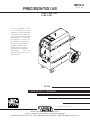
Lincoln Electric Precision TIG 185 Manuel utilisateur
- Catégorie
- Système de soudage
- Taper
- Manuel utilisateur
Ce manuel convient également à

• Sales and Service through Subsidiaries and Distributors Worldwide •
Cleveland, Ohio 44117-1199 U.S.A. TEL: 216.481.8100 FAX: 216.486.1751 WEB SITE: www.lincolnelectric.com
• World's Leader in Welding and Cutting Products •
OPERATOR?S MANUAL
IM832-A
December, 2006
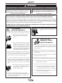
Safety Depends on You
Lincoln arc welding and cutting
equipment is designed and built
with safety in mind. However, your
overall safety can be increased by
proper installation ... and thought-
ful operation on your part. DO
NOT INSTALL, OPERATE OR
REPAIR THIS EQUIPMENT
WITHOUT READING THIS
MANUAL AND THE SAFETY
PRECAUTIONS CONTAINED
THROUGHOUT. And, most
importantly, think before you act
and be careful.
For use with machines having Code Numbers:
Copyright © 2006 Lincoln Global Inc.
PRECISION TIG 185
11105, 11106, 11107
11108, 11109
IP 21S

FOR ENGINE
powered equipment.
1.a. Turn the engine off before troubleshooting and maintenance
work unless the maintenance work requires it to be running.
____________________________________________________
1.b. Operate engines in open, well-ventilated
areas or vent the engine exhaust fumes
outdoors.
____________________________________________________
1.c. Do not add the fuel near an open flame
welding
arc or when the engine is running.
Stop the engine and allow it to cool before
refueling to prevent spilled fuel from vaporiz-
ing on contact with hot engine parts and
igniting. Do not spill fuel when filling tank. If
fuel is spilled, wipe it up and do not start
engine until fumes have been eliminated.
____________________________________________________
1.d. Keep all equipment safety guards, covers and devices in
position
and in good repair.Keep hands, hair, clothing and
tools away from V-belts, gears, fans and all other moving
parts when starting, operating or repairing equipment.
____________________________________________________
1.e. In some cases it may be necessary to remove safety
guards
to perform required maintenance. Remove
guards only when necessary and replace them when the
maintenance requiring their removal is complete.
Always use the greatest care when working near moving
parts.
___________________________________________________
1.f. Do not put your hands near the engine fan.
Do
not attempt to override the governor or
idler by pushing on the throttle control rods
while the engine is running.
___________________________________________________
1.g. To prevent accidentally starting gasoline engines while
turning
the engine or welding generator during maintenance
work, disconnect the spark plug wires, distributor cap or
magneto wire as appropriate.
i
SAFETY
i
ARC WELDING CAN BE HAZARDOUS. PROTECT YOURSELF AND OTHERS FROM POSSIBLE SERIOUS INJURY OR DEATH.
KEEP CHILDREN AWAY. PACEMAKER WEARERS SHOULD CONSULT WITH THEIR DOCTOR BEFORE OPERATING.
Read and understand the following safety highlights. For additional safety information, it is strongly recommended that you
purchase a copy of “Safety in Welding & Cutting - ANSI Standard Z49.1” from the American Welding Society, P.O. Box
351040, Miami, Florida 33135 or CSA Standard W117.2-1974. A Free copy of “Arc Welding Safety” booklet E205 is available
from the Lincoln Electric Company, 22801 St. Clair Avenue, Cleveland, Ohio 44117-1199.
BE SURE THAT ALL INSTALLATION, OPERATION, MAINTENANCE AND REPAIR PROCEDURES ARE
PERFORMED ONLY BY QUALIFIED INDIVIDUALS.
WARNING
Mar ʻ95
ELECTRIC AND
MAGNETIC FIELDS
may be dangerous
2.a. Electric current flowing through any conductor causes
localized Electric and Magnetic Fields (EMF). Welding
current creates EMF fields around welding cables and
welding machines
2.b. EMF fields may interfere with some pacemakers, and
welders having a pacemaker should consult their physician
before welding.
2.c. Exposure to EMF fields in welding may have other health
effects which are now not known.
2.d. All welders should use the following procedures in order to
minimize exposure to EMF fields from the welding circuit:
2.d.1.
Route the electrode and work cables together - Secure
them with tape when possible.
2.d.2. Never coil the electrode lead around your body.
2.d.3. Do not place your body between the electrode and
work cables. If the electrode cable is on your right
side, the work cable should also be on your right side.
2.d.4. Connect the work cable to the workpiece as close as
possible to the area being welded.
2.d.5. Do not work next to welding power source.
1.h. To avoid scalding, do not remove the
radiator pressure cap when the engine is
hot.
CALIFORNIA PROPOSITION 65 WARNINGS
Diesel engine exhaust and some of its constituents
are known to the State of California to cause can-
cer, birth defects, and other reproductive harm.
The engine exhaust from this product contains
chemicals known to the State of California to cause
cancer, birth defects, or other reproductive harm.
The Above For Diesel Engines
The Above For Gasoline Engines

ii
SAFETY
ii
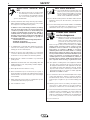
ARC RAYS can burn.
4.a. Use a shield with the proper filter and cover
plates to protect your eyes from sparks and
the rays of the arc when welding or observing
open arc welding. Headshield and filter lens
should conform to ANSI Z87. I standards.
4.b. Use suitable clothing made from durable flame-resistant
material to protect your skin and that of your helpers from
the arc rays.
4.c. Protect other nearby personnel with suitable, non-flammable
screening and/or warn them not to watch the arc nor expose
themselves to the arc rays or to hot spatter or metal.
ELECTRIC SHOCK can
kill.
3.a. The electrode and work (or ground) circuits
are electrically “hot” when the welder is on.
Do not touch these “hot” parts with your bare
skin or wet clothing. Wear dry, hole-free
gloves to insulate hands.
3.b. Insulate yourself from work and ground using dry insulation.
Make certain the insulation is large enough to cover your full
area of physical contact with work and ground.
In addition to the normal safety precautions, if welding
must be performed under electrically hazardous
conditions (in damp locations or while wearing wet
clothing; on metal structures such as floors, gratings or
scaffolds; when in cramped positions such as sitting,
kneeling or lying, if there is a high risk of unavoidable or
accidental contact with the workpiece or ground) use
the following equipment:
• Semiautomatic DC Constant Voltage (Wire) Welder.
• DC Manual (Stick) Welder.
• AC Welder with Reduced Voltage Control.
3.c. In semiautomatic or automatic wire welding, the electrode,
electrode reel, welding head, nozzle or semiautomatic
welding gun are also electrically “hot”.
3.d. Always be sure the work cable makes a good electrical
connection with the metal being welded. The connection
should be as close as possible to the area being welded.
3.e. Ground the work or metal to be welded to a good electrical
(earth) ground.
3.f.
Maintain the electrode holder, work clamp, welding cable and
welding machine in good, safe operating condition. Replace
damaged insulation.
3.g. Never dip the electrode in water for cooling.
3.h. Never simultaneously touch electrically “hot” parts of
electrode holders connected to two welders because voltage
between the two can be the total of the open circuit voltage
of both welders.
3.i. When working above floor level, use a safety belt to protect
yourself from a fall should you get a shock.
3.j. Also see Items 6.c. and 8.
FUMES AND GASES
can be dangerous.
5.a. Welding may produce fumes and gases
hazardous to health. Avoid breathing these
fumes and gases. When welding, keep
your head out of the fume. Use enough
ventilation and/or exhaust at the arc to keep
fumes and gases away from the breathing zone. When
welding with electrodes which require special
ventilation such as stainless or hard facing (see
instructions on container or MSDS) or on lead or
cadmium plated steel and other metals or coatings
which produce highly toxic fumes, keep exposure as
low as possible and below Threshold Limit Values (TLV)
using local exhaust or mechanical ventilation. In
confined spaces or in some circumstances, outdoors, a
respirator may be required. Additional precautions are
also required when welding on galvanized steel.
5. b. The operation of welding fume control equipment is affected
by various factors including proper use and positioning of
the equipment, maintenance of the equipment and the spe-
cific welding procedure and application involved. Worker
exposure level should be checked upon installation and
periodically thereafter to be certain it is within applicable
OSHA PEL and ACGIH TLV limits.
5.c.
Do not weld in locations near chlorinated hydrocarbon
vapors
coming from degreasing, cleaning or spraying operations.
The heat and rays of the arc can react with solvent vapors
to
form phosgene, a highly toxic gas, and other irritating prod-
ucts.
5.d. Shielding gases used for arc welding can displace air and
cause injury or death. Always use enough ventilation,
especially in confined areas, to insure breathing air is safe.
5.e. Read and understand the manufacturerʼs instructions for this
equipment and the consumables to be used, including the
material safety data sheet (MSDS) and follow your
employerʼs safety practices. MSDS forms are available from
your welding distributor or from the manufacturer.
5.f. Also see item 1.b.
AUG 06

FOR ELECTRICALLY
powered equipment.
8.a. Turn off input power using the disconnect
switch at the fuse box before working on
the equipment.
8.b. Install equipment in accordance with the U.S. National
Electrical Code, all local codes and the manufacturerʼs
recommendations.
8.c. Ground the equipment in accordance with the U.S. National
Electrical Code and the manufacturerʼs recommendations.
CYLINDER may explode
if damaged.
7.a. Use only compressed gas cylinders
containing the correct shielding gas for the
process used and properly operating
regulators designed for the gas and
pressure used. All hoses, fittings, etc. should be suitable for
the application and maintained in good condition.
7.b. Always keep cylinders in an upright position securely
chained to an undercarriage or fixed support.
7.c. Cylinders should be located:
• Away from areas where they may be struck or subjected to
physical damage.
• A safe distance from arc welding or cutting operations and
any other source of heat, sparks, or flame.
7.d. Never allow the electrode, electrode holder or any other
electrically “hot” parts to touch a cylinder.
7.e. Keep your head and face away from the cylinder valve outlet
when opening the cylinder valve.
7.f. Valve protection caps should always be in place and hand
tight except when the cylinder is in use or connected for
use.
7.g. Read and follow the instructions on compressed gas
cylinders, associated equipment, and CGA publication P-l,
“Precautions for Safe Handling of Compressed Gases in
Cylinders,” available from the Compressed Gas Association
1235 Jefferson Davis Highway, Arlington, VA 22202.
iii
SAFETY
iii
Mar ʻ95
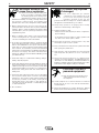
WELDING SPARKS can
cause fire or explosion.
6.a.
Remove fire hazards from the welding area.
If this is not possible, cover them to prevent
the welding sparks from starting a fire.
Remember that welding sparks and hot
materials from welding can easily go through small cracks
and openings to adjacent areas. Avoid welding near
hydraulic lines. Have a fire extinguisher readily available.
6.b. Where compressed gases are to be used at the job site,
special precautions should be used to prevent hazardous
situations. Refer to “Safety in Welding and Cutting” (ANSI
Standard Z49.1) and the operating information for the
equipment being used.
6.c. When not welding, make certain no part of the electrode
circuit is touching the work or ground. Accidental contact
can cause overheating and create a fire hazard.
6.d. Do not heat, cut or weld tanks, drums or containers until the
proper steps have been taken to insure that such procedures
will not cause flammable or toxic vapors from substances
inside. They can cause an explosion even
though
they have
been “cleaned”. For information, purchase “Recommended
Safe Practices for the
Preparation
for Welding and Cutting of
Containers and Piping That Have Held Hazardous
Substances”, AWS F4.1 from the American Welding Society
(see address above).
6.e. Vent hollow castings or containers before heating, cutting or
welding. They may explode.
6.f.
Sparks and spatter are thrown from the welding arc. Wear oil
free protective garments such as leather gloves, heavy shirt,
cuffless trousers, high shoes and a cap over your hair. Wear
ear plugs when welding out of position or in confined places.
Always wear safety glasses with side shields when in a
welding area.
6.g. Connect the work cable to the work as close to the welding
area as practical. Work cables connected to the building
framework or other locations away from the welding area
increase the possibility of the welding current passing
through lifting chains, crane cables or other alternate cir-
cuits. This can create fire hazards or overheat lifting chains
or cables until they fail.
6.h. Also see item 1.c.

iv
SAFETY
iv
Mar. ʻ93
PRÉCAUTIONS DE SÛRETÉ
Pour votre propre protection lire et observer toutes les instructions
et les précautions de sûreté specifiques qui parraissent dans ce
manuel aussi bien que les précautions de sûreté générales suiv-
antes:
Sûreté Pour Soudage A LʼArc
1. Protegez-vous contre la secousse électrique:
a. Les circuits à lʼélectrode et à la piéce sont sous tension
quand la machine à souder est en marche. Eviter toujours
tout contact entre les parties sous tension et la peau nue
ou les vétements mouillés. Porter des gants secs et sans
trous pour isoler les mains.
b. Faire trés attention de bien sʼisoler de la masse quand on
soude dans des endroits humides, ou sur un plancher
metallique ou des grilles metalliques, principalement dans
les positions assis ou couché pour lesquelles une grande
partie du corps peut être en contact avec la masse.
c. Maintenir le porte-électrode, la pince de masse, le câble
de soudage et la machine à souder en bon et sûr état
defonctionnement.
d.Ne jamais plonger le porte-électrode dans lʼeau pour le
refroidir.
e. Ne jamais toucher simultanément les parties sous tension
des porte-électrodes connectés à deux machines à souder
parce que la tension entre les deux pinces peut être le
total de la tension à vide des deux machines.
f. Si on utilise la machine à souder comme une source de
courant pour soudage semi-automatique, ces precautions
pour le porte-électrode sʼapplicuent aussi au pistolet de
soudage.
2. Dans le cas de travail au dessus du niveau du sol, se protéger
contre les chutes dans le cas ou on recoit un choc. Ne jamais
enrouler le câble-électrode autour de nʼimporte quelle partie
du corps.
3. Un coup dʼarc peut être plus sévère quʼun coup de soliel,
donc:
a. Utiliser un bon masque avec un verre filtrant approprié
ainsi quʼun verre blanc afin de se protéger les yeux du ray-
onnement de lʼarc et des projections quand on soude ou
quand on regarde lʼarc.
b. Porter des vêtements convenables afin de protéger la
peau de soudeur et des aides contre le rayonnement de
lʻarc.
c. Protéger lʼautre personnel travaillant à proximité au
soudage à lʼaide dʼécrans appropriés et non-inflammables.
4. Des gouttes de laitier en fusion sont émises de lʼarc de
soudage. Se protéger avec des vêtements de protection libres
de lʼhuile, tels que les gants en cuir, chemise épaisse, pan-
talons sans revers, et chaussures montantes.
5. Toujours porter des lunettes de sécurité dans la zone de
soudage. Utiliser des lunettes avec écrans lateraux dans les
zones où lʼon pique le laitier.
6. Eloigner les matériaux inflammables ou les recouvrir afin de
prévenir tout risque dʼincendie dû aux étincelles.
7. Quand on ne soude pas, poser la pince à une endroit isolé de
la masse. Un court-circuit accidental peut provoquer un
échauffement et un risque dʼincendie.
8. Sʼassurer que la masse est connectée le plus prés possible
de la zone de travail quʼil est pratique de le faire. Si on place
la masse sur la charpente de la construction ou dʼautres
endroits éloignés de la zone de travail, on augmente le risque
de voir passer le courant de soudage par les chaines de lev-
age, câbles de grue, ou autres circuits. Cela peut provoquer
des risques dʼincendie ou dʼechauffement des chaines et des
câbles jusquʼà ce quʼils se rompent.
9. Assurer une ventilation suffisante dans la zone de soudage.
Ceci est particuliérement important pour le soudage de tôles
galvanisées plombées, ou cadmiées ou tout autre métal qui
produit des fumeés toxiques.
10. Ne pas souder en présence de vapeurs de chlore provenant
dʼopérations de dégraissage, nettoyage ou pistolage. La
chaleur ou les rayons de lʼarc peuvent réagir avec les vapeurs
du solvant pour produire du phosgéne (gas fortement toxique)
ou autres produits irritants.
11. Pour obtenir de plus amples renseignements sur la sûreté,
voir le code “Code for safety in welding and cutting” CSA
Standard W 117.2-1974.
PRÉCAUTIONS DE SÛRETÉ POUR
LES MACHINES À SOUDER À
TRANSFORMATEUR ET À
REDRESSEUR
1. Relier à la terre le chassis du poste conformement au code de
lʼélectricité et aux recommendations du fabricant. Le dispositif
de montage ou la piece à souder doit être branché à une
bonne mise à la terre.
2. Autant que possible, Iʼinstallation et lʼentretien du poste seront
effectués par un électricien qualifié.
3. Avant de faires des travaux à lʼinterieur de poste, la debranch-
er à lʼinterrupteur à la boite de fusibles.
4. Garder tous les couvercles et dispositifs de sûreté à leur
place.

v
SAFETY
v

vi
SAFETY
vi

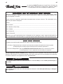
Thank You
for selecting a QUALITY product by Lincoln Electric. We want you
to take pride in operating this Lincoln Electric Company product
••• as much pride as we have in bringing this product to you!
Read this Operators Manual completely before attempting to use this equipment. Save this manual and keep it
handy for quick reference. Pay particular attention to the safety instructions we have provided for your protection.
The level of seriousness to be applied to each is explained below:
WARNING
This statement appears where the information must be followed exactly to avoid serious personal injury or
loss of life.
This statement appears where the information must be followed to avoid minor personal injury or damage to
this equipment.
CAUTION
Please Examine Carton and Equipment For Damage Immediately
When this equipment is shipped, title passes to the purchaser upon receipt by the carrier. Consequently, Claims
for material damaged in shipment must be made by the purchaser against the transportation company at the
time the shipment is received.
Please record your equipment identification information below for future reference. This information can be
found on your machine nameplate.
Product _________________________________________________________________________________
Model Number ___________________________________________________________________________
Code Number or Date Code_________________________________________________________________
Serial Number____________________________________________________________________________
Date Purchased___________________________________________________________________________
Where Purchased_________________________________________________________________________
Whenever you request replacement parts or information on this equipment, always supply the information you
have recorded above. The code number is especially important when identifying the correct replacement parts.
viivii
On-Line Product Registration
- Register your machine with Lincoln Electric either via fax or over the Internet.
• For faxing: Complete the form on the back of the warranty statement included in the literature packet
accompanying this machine and fax the form per the instructions printed on it.
• For On-Line Registration: Go to our
WEB SITE at www.lincolnelectric.com. Choose “Quick Links” and then
“Product Registration”. Please complete the form and submit your registration.

viii
viii
TABLE OF CONTENTS
Page
Installation.......................................................................................................................Section A
Technical Specifications ................................................................................................A-1,A-2
Safety Precautions ...............................................................................................................A-3
Select Suitable Location................................................................................................A-3
Grinding.........................................................................................................................A-3
Stacking ........................................................................................................................A-3
Tilting.............................................................................................................................A-3
Lifting and Moving .........................................................................................................A-3
Tilting.............................................................................................................................A-3
Environmental Rating....................................................................................................A-3
Machine Grounding and High Frequency Interference Protection................................A-3, A-4
Input Connections .........................................................................................................A-4
Input Reconnect Procedure ..........................................................................................A-5
Output Connections..............................................................................................................A-5
Connections For Tig (GTAW) Welding..........................................................................A-5
Tig Torch Connections ..................................................................................................A-5
Work Cable Connections ..............................................................................................A-5
Shielding Gas Connection.............................................................................................A-6
Remote Control Connection..........................................................................................A-6
Connections For Stick (SMAW) Welding .............................................................................A-6
Stick Electrode Cable and Work Cable Connection......................................................A-6
________________________________________________________________________________
Operation.........................................................................................................................Section B
Safety Precautions ...............................................................................................................B-1
Graphic Symbols ..................................................................................................................B-1
Product Description ..............................................................................................................B-1
Recommended Processes and Equipment...................................................................B-2
Recommended Processes.. ..........................................................................................B-2
Process Limitations ......................................................................................................B-2
Recommended Equipment/Interface.............................................................................B-2
Equipment Limitations...................................................................................................B-2
Welding Capability................................................................................................................B-2
Controls and Settings ...................................................................................................B-3, B-4
Operating Steps ...................................................................................................................B-4
Welding in TIG Mode ....................................................................................................B-4
Pulse TIG Mode ............................................................................................................B-4
Remote Control Operation ............................................................................................B-5
Benefits of the Precision TIG 185 .................................................................................B-5
Welding in Stick Mode..........................................................................................................B-6
________________________________________________________________________________
Accessories.....................................................................................................Section C
Factory Installed Options.......................................................................................C-1
Field Installed Options...........................................................................................C-1
________________________________________________________________________
Maintenance ....................................................................................................Section D
Safety Precautions ................................................................................................D-1
Routine and Periodic Maintenance........................................................................D-1
________________________________________________________________________
Troubleshooting..............................................................................................Section E
Safety Precautions.................................................................................................E-1
How to Use Troubleshooting Guide.......................................................................E-1
Troubleshooting ..................................................................................E-2 THRU E-7
________________________________________________________________________
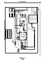
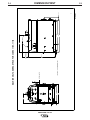
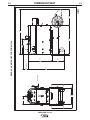
Diagrams .........................................................................................................Section F
Wiring Diagram ......................................................................................................F-1
Dimension Print......................................................................................................F-2
________________________________________________________________________
Parts List .................................................................................................P499,P210,P66

A-1
INSTALLATION
PRECISION TIG 185
A-1
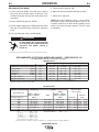
TECHNICAL SPECIFICATIONS - PRECISION TIG 185 (K2345-1AND K2347-1,-2)
Volts at Rated Amperes
15.2 V AC/DC
14.1 V AC/DC
13.8 V AC/DC
27.4 V AC/DC
23.6 V AC/DC
Type of Output
CC (Constant Current)
AC/DC
Amps
185A AC/DC
90A AC/DC (BAL)
70A AC (AUTO-BAL)
185A AC/DC125
90A AC/DC
Maximum Open
Circuit Voltage
(STICK AND TIG)
AC OCV: 75
DC OCV: 59
Input Current at Rated Output
35A / 32A Effective
and 70A / 64A Maximum
Duty Cycle
GTAW 15% Duty Cycle
100% Duty Cycle
SMAW 15% Duty Cycle
100% Duty Cycle
Output Current
Range
7-185 Amps (AC)
5-185 Amps (DC)
Standard Voltage
208/230/1/60
INPUT - SINGLE PHASE ONLY
OUTPUT RANGE
RATED OUTPUT
Chart gives max. rated Output Amps @% Duty Cycle (Based on a 10 minute cycle)
(Example; 110A@60% for AC/DC Stick and Balance TIG)
Using standa
r
d #8-3 input cable for protec
t
ed
(1)
input supply
0%
10%
20%
30%
40%
50%
60%
70%
80%
90%
100%
507090110 130150170190
208/230v Model: 208/230vModel:AC/DC Stick & DC AC/DCStick&DCTIGTIG
(AC (ACTIG with #6-3 input cable)TIGwith#6-3inputcable)
460/575v Model: 460/575vModel:AC/DC Stick & AC/DCStick&AC/DC AC/DCTIGTIG
380/415v Model: 380/415vModel:AC/DC Stick & AC/DCStick&
DC/AC DC/ACAuto-Bal.TIGAuto-Bal.TIG
208/230v Model: 208/230vModel:AC ACTIG using 230v inputTIGusing230vinput
380/415v Model: 380/415vModel:AC ACTIG (Max. Penetration)TIG(Max. Penetration)
208/230v Model: 208/230vModel:AC ACTIG using 208v inputTIGusing208vinput
OUTPUT AMPS
OUTPUT % DUTY CYCLE
U s i n g s t an d a
r
d #8-3 input cable for protec
t
ed
(1)
input supply
0%
10%
20%
30%
40%
50%
60%
70%
80%
90%
100%
50 70 90 110 130 150 170 190
208/230v Model: 208/230v Model: AC/DC Stick & DC AC/DC Stick & DC TIGTIG
(AC (AC TIG with #6-3 input cable)TIG with #6-3 input cable)
460/575v Model: 460/575v Model: AC/DC Stick & AC/DC Stick & AC/DC AC/DC TIGTIG
380/415v Model: 380/415v Model: AC/DC Stick & AC/DC Stick &
DC/AC DC/AC Auto-Bal.TIGAuto-Bal.TIG
208/230v Model: 208/230v Model: AC AC TIG using 230v inputTIG using 230v input
380/415v Model: 380/415v Model: AC AC TIG (Max. Penetration)TIG (Max. Penetration)
208/230v Model: 208/230v Model: AC AC TIG using 208v inputTIG using 208v input
OUTPUT AMPS
OUTPUT % DUTY CYCLE
(1)
Wiring and protection based on the 2002 U.S. National Electric Code:
Use a Super Lag type fuse or circuit breaker with a delay in tripping action.
Models with NEMA 6-50P plug may be used with a 50 amp protected 6-50R receptacle, or
with a maximum 70 amp protected 6-50R receptacle if dedicated for the welder.

A-2
INSTALLATION
PRECISION TIG 185
A-2
TECHNICAL SPECIFICATIONS - CANADIAN (K2345-2), INTERNATIONAL K2346-1)
MODEL HEIGHT WIDTH DEPTH WEIGHT
PHYSICAL DIMENSIONS
(2)
Weld Voltage (NEMA)
27.4 V
23.6 V
15.2 V
14.1 V
Output Type
CC (Constant Current)
AC or DC
Weld Current
185 A AC/DC
90 A AC/DC
185 A AC/DC
90 A AC/DC (Auto-Bal.)
Weld Current
7-185 A (AC)
5-185 A (DC).
Process Duty Cycle*.
SMAW
15%
100%
GTAW
15%
100%
Max. OCV.
74 V (AC)
59 V (DC)
OUTPUT RANGE
RATED OUTPUT
Machine Only
(K2345-1,-2)
(K2346-1)
Ready-Pak
(K2347-1)
Ready-PakW/Cart
(K2347-2)
20.71 in.
526 mm
20.71 in.
526 mm
31.24 in.
794 mm
14.48 in.
368 mm
14.48 in.
368 mm
19.81 in.
503 mm
25.62 in.
751 mm
25.62 in.
651 mm
38.01 in.
966 mm
Approx. 192 lbs.
87.1 kgs
Approx. 212lbs..
96.2 kgs.
Approx. 258lbs.
117.0 kgs.
(2)
Dimensions are without Lift Eyebolt and Torch Holder
Power Factor
0.62 Min.
Idle Current
1.3 A/1.0 A Max.
Current
16 A/13 A Effective
32 A/26 A Max.
Voltage/Phase/Freq.
460/575/1/60
K2345-2 INPUT (at Rated Output)
K2346-1 INPUT (at Rated Output)
Power Factor
0.62 Min.
Idle Current
1.3 A/1.0 A Max.
Current
19 A/18 A Effective
39 A/37 A Max.
Voltage/Phase/Freq.
380/400-415/1/50/60
* Based on a 10 minute cycle.
N80

A-3
INSTALLATION
PRECISION TIG 185
A-3
SAFETY PRECAUTIONS
SELECT SUITABLE LOCATION
Place the welder where clean cooling air can freely
circulate in and out through the rear louvers. Dirt, dust
or any foreign material that can be drawn into the
welder should be kept at a minimum. Failure to
observe these precautions can result in excessive
operating temperatures and nuisance shut-downs.
GRINDING
Do not direct grinding particles towards the welder. An
abundance of conductive material can cause mainte-
nance problems.
STACKING
PRECISION TIG 185 cannot
be stacked.
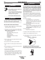
LIFTING AND MOVING
The PRECISION TIG 185 models are provided with
an Eyebolt used for lifting the unit with a hoist. To
install; remove the plug button from the case top and
screw the Eyebolt securely into the threaded bracket
beneath the case top per the below instructions and
warnings provided on the case top decal. Save the
removed plug button (LE part No.T10397-2) to cover
the hole when the lift Eyebolt is removed.
An undercarriage, provided on the Ready-Pak w/Cart
model, is also available to easily move the the unit.
Refer to the Accessories section of this manual.
Do not attempt to lift the power source with an
undercarriage attached.
The undercarriage is designed for hand moving only;
mechanized movement can lead to personal injury
and/or damage to the PRECISION TIG 185.
TILTING
Each machine must be placed on a secure, level sur-
face, either directly or on a recommended undercar-
riage. The machine may topple over if this procedure
is not followed.
ENVIRONMENTAL RATING
The PRECISION TIG 185 power source carries an
IP21 environmental rating. It may be used in normal
industrial and commercial environments. Avoid using
it in environments which have falling water such as
rain.
Read and follow “Electric Shock Warnings” in the
Safety section if welding must be performed under
electrically hazardous conditions such as welding in
wet areas or on or in the workpiece.
MACHINE GROUNDING AND HIGH FRE-
QUENCY INTERFERENCE PROTECTION
This welder must be grounded! See your local and
national electrical codes for proper grounding
methods.
ELECTRIC SHOCK can kill.
• Only qualified personnel should
perform this installation.
• Turn the input power OFF at the
disconnect switch or fuse box
before working on this equipment.
• Do not touch electrically hot
parts.
• Always connect the PRECISION TIG 185 to a power
supply grounded per the National Electrical Code
and any local codes.
---------------------------------------------------------------------------
WARNING
Read entire installation section before starting
installation.
• Use only Lincoln provided
T4550-5 1/2-13 x 1.00 eyebolt.
• Fully engage threads and
torque eyebolt to 38 ft. lbs.
• Re-torque eyebolt to 38 ft. lbs.
before each lift.
• Lift only with equipment of
adequate lifting capacity.
FALLING • Never lift welder with gas
EQUIPMENT cylinder attached.
can cause injury. • Never lift welder above per-
sonnel.
• Lift only with equipment of adequate lifting
capacity.
• Be sure machine is stable when lifting.
------------------------------------------------------------------------
WARNING

A-4
INSTALLATION
PRECISION TIG 185
A-4
The high frequency generator, being similar to a radio
transmitter, may cause radio, TV and electronic equip-
ment interference problems. These problems may be
the result of radiated interference. Proper grounding
methods can reduce or eliminate radiated interfer-
ence.
Radiated interference can develop in the following
four ways:
1. Direct interference radiated from the welder.
2. Direct interference radiated from the welding leads.
3. Direct interference radiated from feedback into the
power lines.
4. Interference from re-radiation of “pickup” by
ungrounded metallic objects.
Keeping these contributing factors in mind, installing
equipment per the following instructions should mini-
mize problems.
1. Keep the welder power supply lines as short as
possible. Input leads within 50 feet (15.2m) of the
welder should be enclosed in rigid metallic conduit
or equivalent shielding. There should be good elec-
trical contact between this conduit and the welder
case ground. Both ends of the conduit should be
connected to a driven ground and the entire length
should be continuous.
2. Keep the work and electrode leads as short as pos-
sible and as close together as possible. Lengths
should not exceed 25 ft (7.6m). Tape the leads
together when practical.
3. Be sure the torch and work cable rubber coverings
are free of cuts and cracks that allow high frequen-
cy leakage.
4. Keep the torch in good repair and all connections
tight to reduce high frequency leakage.
5. The work piece must be connected to an earth
ground close to the work clamp, using one of the
following methods:
a) A metal underground water pipe in direct contact
with the earth for ten feet or more.
b) A 3/4” (19mm) galvanized pipe or a 5/8”
(16mm)solid galvanized iron, steel or copper rod
driven at least eight feet into the ground.
The ground should be securely made and the ground-
ing cable should be as short as possible using cable
of the same size as the work cable, or larger.
Grounding to the building frame electrical conduit or
along pipe system can result in re-radiation, effectively
making these members radiating antennas.
6. Keep cover and all screws securely in place.
7. Electrical conductors within 50 ft (15.2m) of the
welder should be enclosed in grounded rigid metal-
lic conduit or equivalent shielding, wherever possi-
ble. Flexible metallic conduit is generally not suit-
able.
8. When the welder is enclosed in a metal building,the
metal building should be connected to several good
earth driven electrical grounds (as in 5 (b) above)
around the periphery of the building.
Failure to observe these recommended installation
procedures can cause radio or TV and electronic
equipment interference problems and result in unsat-
isfactory welding performance resulting from lost high
frequency power.
INPUT CONNECTIONS
Be sure the voltage, phase, and frequency of the input
power is as specified on the rating plate, located on
the rear of the machine.
208/230 volt models have a NEMA 6-50P plug
attached to the #8-3 input power cord and a NEMA 6 -
50R receptacle is included with the Ready-Pak mod-
els. Other voltage models have an input power cord
but no plug or receptacle.
Have a qualified electrician provide input power sup-
ply to the receptacle or cord in accordance with all
local and national electrical codes. Use a single phase
line or one phase of a two or three phase line. Choose
an input and grounding wire size according to local or
national codes. Refer to the Technical
Specifications page at the beginning of this section.
Fuse the input circuit with the recommended super lag
fuses or delay type
1
circuit breakers. Using fuses or
circuit breakers smaller than recommended may result
in “nuisance” shut-offs from welder inrush currents
even if not welding at high currents.
1
Also called “inverse time” or “thermal/magnetic” circuit breakers;
circuit breakers which have a delay in tripping action that decreases
as the magnitude of the current increases.

A-5
INSTALLATION
PRECISION TIG 185
A-5
INPUT RECONNECT PROCEDURE
On multiple input voltage welders, be sure the
machine is connected per the following instructions
for the voltage being supplied to the welder.
Failure to follow these instructions can cause immedi-
ate failure of components within the welder and void
machineʼs warranty.
-----------------------------------------------------------------------
Multiple voltage models are shipped connected for the
highest voltage. To change this connection refer to the
following instructions.
ELECTRIC SHOCK can kill.
• Turn the input power OFF at the dis-
connect switch or fuse box before
working on this equipment.
------------------------------------------------------------------------
For the lowest rated voltage connection (Refer to figure A.1):
1. Remove the sheet metal left side cover.
2. Disconnect lead H3 from the power switch and
insulate with the insulation from the H2 lead.
3. Connect lead H2 to the power switch where H3 was
connected.
4. Tighten connections.
5. Replace sheet metal cover and all screws
For the highest rated voltage connection (Refer to figure A.1):
The machine is normally shipped connected for the
highest rated voltage, however verify the following:
1. Remove the sheet metal left side cover.
2. Disconnect lead H2 from the power switch and
insulate with the insulation from the H3 lead.
3. Connect lead H3 to the line switch where H2 was
connected.
4. Tighten connections.
5. Replace sheet metal cover and all screws.
CONNECTIONS FOR TIG (GTAW) WELDING
TIG TORCH CONNECTION
Refer to Included Equipment in the Operation
Section of this manual for TIG welding equipment
which is included with the PRECISION TIG 185.
CAUTION
WARNING
FIGURE A.1 Reconnect Leads
INPUT LEADS INPUT LEADS
L1 & L2L1 & L2
LEAD H1LEAD H1
(DO NOT (DO NOT
REMOVE)REMOVE)
FOR LOWEST RATED VOLTAGEFOR LOWEST RATED VOLTAGE
: H2 CONNECTED: H2 CONNECTED
FOR HIGHEST RATED VOLTAGEFOR HIGHEST RATED VOLTAGE
: H3 CONNECTED: H3 CONNECTED
BACK VIEW OF LINE SWITCHBACK VIEW OF LINE SWITCH
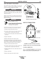
OUTPUT CONNECTIONS
FIGURE A.2 Location of Output Connections
ELECTRODE/GAS
OUTLET
RECEPTACLE
(TWIST-MATE)
WORK CABLE & CLAMP

A-6
INSTALLATION
PRECISION TIG 185
A-6
A PTA-17 Twist-Mate TIG welding torch with cable
and connector is supplied with the Ready-Pak Models
and available for other models (See Accessories
Section). Turn the Power Switch “OFF”. Connect the
torch cable Twist-Mate quick connect plug into the
Electrode/Gas Output Receptacle on the front of the
welder and turn it clockwise until it is tight. This is a
Twist-Mate quick connect terminal and also provides
the gas connection for the shielding gas to the torch.
To avoid receiving a high frequency shock, keep
the TIG torch and cables in good condition.
------------------------------------------------------------------------
WORK CABLE CONNECTION
A work cable with attached work clamp is factory con-
nected to the PRECISION TIG 185. To minimize high
frequency interference, refer to Machine Grounding
and High Frequency Interference Protection sec-
tion of this manual for the proper procedure on
grounding the work clamp and work piece.
SHIELDING GAS CONNECTION
An adjustable gas pressure regulator with flow gage
and hose is supplied with the PRECISION TIG 185
Ready-Pak Models and available separately for other
models (See Accessories Section). Obtain the neces-
sary inert shielding gas (usually argon). Connect the
cylinder of gas with the pressure regulator and flow
gage. Install the gas hose between the regulator and
gas inlet (located on the rear of the welder). The gas
inlet has a 5/16-18 right hand female thread;
CGA#032.
The availiable Under-Storage Cart features a low plat-
form that simplifies loading and unloading of gas cylin-
ders.
CYLINDER could explode
if damaged.
• Keep cylinder upright and chained
to a support.
• Keep cylinder away from areas
where it could be damaged.
• Never allow the torch to touch the cylinder.
• Keep cylinder away from live electrical circuits.
• Maximum inlet pressure 150 psi.
------------------------------------------------------------------------
A cylinder is loaded by leaning it slightly sideways and
rocking it up on the platform, being careful not to
allow the Under-Storage Cart to roll. Secure the
cylinder in place with the provided chain. Unload
by following these steps in reverse.
REMOTE CONTROL CONNECTION
A remote control receptacle is provided on the case
front of the welder for connecting a remote control to
to the machine. A Foot Amptrol™, foot activated
remote control, is included with the PRECISION TIG
185 Ready-Pak models and availiable separately for
other models. Refer to the Optional Accessories sec-
tion of this manual for other available remote controls.
CONNECTIONS FOR STICK (SMAW)
WELDING
STICK ELECTRODE CABLE AND WORK CABLE
CONNECTION
Refer to Field Installed Options in Accessories Section
of this manual for STICK welding equipment which is
availiable for use with the PRECISION TIG 185. An
electrode holder with Twist-Mate cable and Twist-
Mate connector are availiable separately for use with
the PRECISION TIG 185. (See Accessories Section).
Turn the Power Switch “OFF”. Connect the Twist-
Mate quick connect plug into the Electrode/Gas
Output Receptacle and turn it clockwise until it is tight.
The work cable and work clamp are factory connect-
ed.
WARNING
WARNING

B-1
OPERATION
PRECISION TIG 185
B-1
ELECTRIC SHOCK
can kill.
• Do not touch electrically live parts
or electrode with skin or wet cloth-
ing.
•
Insulate yourself from work and
ground.
• Always wear dry insulating gloves.
•
Read and follow “Electric Shock Warnings” in the
Safety section if welding must be performed under
electrically hazardous conditions such as welding in
wet areas or on or in the workpiece.
--------------------------------------------------------------------------------
FUMES AND GASES
can be dangerous.
• Keep your head out of fumes.
• Use ventilation or exhaust at the
arc, or both, to remove fumes and
gases from breathing zone and
general area.
------------------------------------------------------------------------
WELDING SPARKS can cause fire or
explosion
• Keep flammable material away.
• Do not weld on containers that
have held combustibles.
------------------------------------------------------------------------
ARC RAYS can burn.
• Wear eye, ear and body
protection.
------------------------------------------------------------------------
SAFETY PRECAUTIONS
Read and understand this entire section before oper-
ating the machine.
Observe additional Safety Guidelines detailed in
the beginning of this manual.
------------------------------------------------------------------------
WARNING
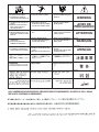
INPUT POWER
POSITIVE OUTPUT
NEGATIVE OUTPUT
DIRECT CURRENT
PROTECTIVE
GROUND
WARNING OR
CAUTION
DO NOT SWITCH
WHILE WELDING
GRAPHIC SYMBOLS THAT APPEAR ON
THIS MACHINE OR IN THIS MANUAL

B-2
OPERATION
B-2
PRODUCT DESCRIPTION
The PRECISION TIG 185 is a member of our field
acclaimed Precision TIG family of industrial arc weld -
ing power sources. Premium features include:
1. Precise constant current output.
2. Full range square wave AC/DC TIG (GTAW) weld--
ing.
3. Enhanced version of the patented Micro-
Start™Technology for its lower Minimum(5 amps)
to higher Maximum (185 amps) output control
range.
4. Built-in high frequency stabilization for DC TIG
starting and continuous AC TIG welding.
5. AC/DC Stick (SMAW capability.) A new undercar-
riage (with gas bottle rack) is available for field
installation, or is included with an available Ready-
Pak TIG Welding Package. The Precision TIG
patented convenient built-in storage provisions for
welding components and cable management.
The PRECISION TIG 185 also provides advanced
features such as:
• Digital Meter
• Presettable control, adjustable Auto Balance™
• Fan As Needed (F.A.N.)
• Timers for fixed Preflow and variable Postflow
shielding gas.
• Built-in, easy to set single knob Pulse TIG control
with a "blinking" light to indicate the pulse frequency
setting.
• Auto-Sense remote control selection.
• Tool-less Twist-Mate electrode cable connection.
• Built-in work clamp cable permanently attached.
Four models are available for 60Hz. with Domestic
and Canadian input voltages, as well as an
International model with 50/60Hz voltages.
RECOMMENDED PROCESSES AND
EQUIPMENT
RECOMMENDED PROCESSES
The PRECISION TIG 185 is recommended for the
TIG (GTAW) and Stick (SMAW) welding processes
within its output capacity range of 5 amps DC,or 7
amps AC, to 185 amps AC/DC. It is compatible with
most Magnum TIG accessories, as well as many
industry standard items, such as TIG torches (adapted
for Twist-Mate), hoses, and water coolers.
PROCESS LIMITATIONS
The PRECISION TIG machines are not recommended
for arc gouging due to it's limited output capacity, and
are also not recommended for pipe thawing.
RECOMMENDED EQUIPMENT/INTERFACE
(See Installed Options in Accessories Section for
more details)
The PRECISION TIG 185 will be available as a basic
Machine (Only) and in two Factory-Configured
Welding Packages:
1. Machine(Only) (K2345-1)
2. Ready-Pak (K2347-1)
3. Ready-Pak w/Cart (K2347-2)
Basic module will also be available as with Domestic,
Canadian and International input voltages for user
configuration, with optional accessories.
Select Machine 208/230/1/60 Machine with 6 NEMA 6-50P
Plug Cable and Receptacle (K2345-1)
460/575/1/60 Machine only with cable (K2345-2)
380/400/415/1/50/60 Machine only
with cable (K2346-1)
Torch Starter Kit Air Cooled System: Water Cooled System:
(Select one) TIG-Mate TIG-Mate 20
Torch Starter Kit* Torch Starter Kit*
Water Cooler Not Applicable 115V 50/60Hz
Cool-Arc 40*
Under-Storage K2348-(*)
Cart (Optional )
Optional Remote Arc Start Switch*
Trigger Device Foot Amptrol*
(Select one) Start Pedal Foot Amptrol*
Hand Amptrol*
*For “Part Numbers” or “K Numbers” see Accessories Section.
EQUIPMENT LIMITATIONS
The PRECISION TIG machines are protected from
over loads beyond the output ratings and duty cycles,
per the Specifications in the Installation Section, with
Thermostat protection of the output power coils and
rectifiers.
The PRECISION TIG 185 machine uses Twist-Mate
output terminals, therefore stud connection adapters
(such as LECO. S19257-series) cannot be used for
torch connection.
If a PRECISION Tig 185 is powered from an engine
generator which doesnʼt have sufficient capacity, the
AC Balance control and the Output control will not
provide full range of control.
WELDING CAPABILITY(Duty Cycle)
The PRECISION TIG 185 is rated at 185 amps, 27
volts, at 15% duty cycle on a ten minute basis. It is
capable of higher duty cycles at lower output currents.
See rated output graph, on specification sheet located
in the Installation Section. If the duty cycle is exceed-
ed, a thermal protector will shut off the output until the
machine cools.
PRECISION TIG 185

B-3
OPERATION
B-3
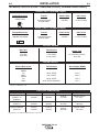
CONTROL FUNCTIONALITY
1. POWER SWITCH – Input line switch turns input
power ON or OFF, as indicated by the on or off sta-
tus of the front panel digital display (See Item 6).
2. POLARITY SWITCH – The rotary power switch has
3-positions for DC+, AC and DC- selections for the
electrode output stud welding polarity.
• Do not switch the polarity switch
while welding or damage may result
to the machine.
------------------------------------------------------------------------
3. MODE SWITCH – The push button switch allows
selection of the two machine welding modes as
indicated by colored mode lights:
• STICK mode – Top position Red light.
• TIG mode – Bottom position Green light.
4. AC BALANCE CONTROL – The AC Balance
Control permits adjustment of the AC TIG wave bal-
ance adjustment from Max. Penetration (80% nega-
tive wave) at full CW rotation setting, to Max.
Cleaning (60% positive wave) at CCW rotation, and
includes:
• Auto Balance position indicated by the Green panel
light turning on.
This setting position feature automatically provides the
proper amount of cleaning and penetration for normal
AC TIG welding.
5. MAXIMUM OUTPUT CONTROL – Presets the out-
put welding current over the rated output range of
the machine:
• With a Remote Current Control (Amptrol) connect-
ed to the Remote Receptacle (See item 10), this
knob sets the Maximum output current level set
table with the remote Amptrol.
• For Pulse TIG (See Item 8) this knob sets the
Peak Pulse level, with the Remote Amptrol (if
used).
6. DIGITAL METER – A 3 digit LED meter is used to
display the preset output current level before weld-
ing, and actual output level while welding:
• A lit display indicates input power is turned on.
(See Item 1.)
7. POST FLOW TIME – Sets the TIG mode shielding
gas post flow time over the range of about 1 to 30
seconds after the arc is shut off.
Note: Gas preflow time is fixed at 0.5 second only in
TIG mode, but no preflow time will occur if the arc is
restarted during Post Flow time, since shielding gas
would not have stopped flowing.
PRECISION TIG 185
CONTROLS AND SETTINGS
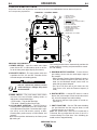
All operator controls and adjustments are located on the front of the PRECISION TIG 185. Refer to Figure B.1
and corresponding explanations.
FIGURE B.1 - CONTROL PANEL
1. POWER SWITCH
2. POLARITY SWITCH
3. MODE SWITCH
4. AC BALANCE CONTROL
5. MAXIMUM OUTPUT CONTROL (AMPS)
6. DIGITAL METERS
7. POST FLOW TIME
8. PULSE TIG CONTROL
9. THERMAL SHUTDOWN LIGHT
10. REMOTE RECEPTACLE
11. ELECTRODE/GAS OUTPUT
RECEPTACLE
12. WORK CABLE
13. REMOVABLE LIFT EYEBOLT
5
13
2
6
3
4
1
7
9
10
11
12
8
CAUTION

B-4
OPERATION
B-4
8. PULSE TIG CONTROL – The Pulse TIG feature
built into the Precision TIG 185 is simplified to be a
single knob control which sets the Pulse Frequency
over the peak pulses/sec. range of about 0.1 to 20
pulses per second:
• Full CCW (min.) setting of the control knob shuts
off Pulse TIG (0.0 pps).
• Peak Pulse level is set by the Max. Output Control
and the Remote Amptrol (if used).
• Background Current level is typically optimized at
a fixed 50% of Peak Pulse level setting.
• Peak Pulse % On-time is typically optimized at a
fixed50%.
A Green light "blinks" with each Peak Pulse to indi-
cate the Pulse TIG Control setting before and dur-
ing welding.
9. OVER TEMPERATURE LIGHT - If the welder
overheats due to blocked air flow, high ambient air
temperature, or exceeded duty cycle, an internal
thermostat will open disabling the welding output
and this yellow light will illuminate. The cooling fans
will continue to run to cool the unit during this time.
The light will go out when the unit cools and the
thermostat resets. Once the light goes out, the
machine will again become available to weld.
10. REMOTE RECEPTACLE – Provides for connec-
tion of remote control and/or arc start switch only
in TIG Mode: ( There is no remote output control
capability when stick welding.
• Plugging a remote current control (Amptrol) into
this receptacle automatically switches the output
control from the panel Max Output Control (See
Item 5) to the remote control.
• The connected remote control will then control
the output current between the Min. range of the
machine and the setting of the panel Max Output
Control.
• Switching Mode Switch (See Item 3) to Stick will
automatically disable the connected remote con-
trol and switch the output control back to the Max
Output panel control.
11. ELECTRODE/GAS OUTPUT RECEPTACLE -
This quick connect Twist-Mate receptacle provides
electrical connection to the electrode holder and
cable for Stick welding and a combined electrical
and gas connection for the TIG torch when TIG
welding.
12. WORK CABLE - This work cable is factory con-
nected to the welder and is connected to the work
piece to complete the welding circuit. Refer to
Machine Grounding and High Frequency
Interference Protection in the Installation section
of this manual for the proper procedure on ground-
ing the work clamp and work piece to minimize
high frequency interference.
OPERATING STEPS
WELDING IN TIG MODE
1. Connect the TIG torch and cable Twist-Mate quick
connect plug to the Electrode/Gas output recepta-
cle. This receptacle also contains an integral gas
connection for the torch. Connect the work clamp to
the work piece.
2. Set the TIG/STICK switch to “TIG”.
3. Set the Polarity Switch to DC- for welding steel or
stainless steel; or to AC for welding aluminum.
4. Connect the Foot Amptrol to the Remote Control
Connector.
5. Turn on the cylinder gas valve and adjust the flow
regulator to obtain desired flow.
6. Turn the power switch to “ON”. NOTE: There will be
a 15 second gas flow when the power is turned on.
7. Preset the Output Control on the control panel to
the maximum desired amps, as read on the digital
meter.
8. Depress the Foot Amptrol to energize the torch and
establish an an arc with the work piece. The digital
meter reads the actual amps while welding.
NOTE: When the TIG/STICK switch is set to “TIG”,
depressing the remote control will start a 0.5 second
gas pre-flow before energizing the TIG torch. When
the remote control is released the TIG torch is de-
energized and gas flow will continue for the time set
by the Post Flow Time control. When the polarity
switch is set to DC, the TIG Arc Starter will turn on
and off automatically to start and stabilize the arc. In
AC the TIG Arc Starter will turn on with the output and
remain on continuously until the remote control is
released.
PULSE TIG CONTROL
Use this knob to set the frequency or the number of
pulses per second(pps), from 0.1pps to 20pps.
• This setting adjusts heat output and bead shape for
travel speed. Thinner plate that is welded with faster
travel speed will require higher frequency than thick-
er plate with slower travel speed. 2-3pps is a typical
starting point.
PRECISION TIG 185

B-5
OPERATION
B-5
REMOTE CONTROL OPERATION
A Foot Amptrol ™is included with the PRECISION
TIG 185 Ready-Pak models and availiable for other
models (See Accessories Section) for remote current
control while TIG welding. An optional Hand Amptrol
may also be used. An optional Arc Start Switch may
be used to start and stop the welding if no remote
control of the current is desired. Refer to the
Accessories Section of this manual.
Both the Hand and Foot Amptrol work in a similar
manner. For simplicity, the following explanation will
refer only to “Amptrols”, meaning both Foot and Hand
models. The term “minimum” refers to a foot pedal in
the “up” position, as it would be with no foot pressure,
or a Hand Amptrol in the relaxed position, with no
thumb pressure.
“Maximum” refers to a fully depressed Foot Amptrol,or
a fully extended Hand Amptrol.
When the welder is in TIG modes activating the
Amptrol energizes the electrode terminal and varies
the output welding current from its minimum value of 5
Amp (DC) or 7 Amp (AC), to the maximum value set
by the Current Control on the control panel. This helps
eliminate accidental high current damage to the work
piece and/or tungsten, and provides a fine control of
the current. When the welder is in the stick mode a
remote control has no effect and is not used.
It is important to note that, in some cases, the tung-
sten will not start an arc at the minimum current
because the tungsten may be too large or cold. To
start an arc reliably, it is important to depress the
Amptrol far enough so that the machine output current
is near the tungsten operating range. For example, a
3/32” tungsten may be used on DC- to weld over the
full range of the machine.
To start the arc, the operator may have to turn the cur-
rent control up and depress the Amptrol approximately
1/4 of the way down. Depressing the Amptrol to its
minimum position may not start the arc. Also if the
current control is set too low, the arc may not start. In
most cases, a large or cold tungsten will not readily
establish an arc at low currents. This is normal. In
Direct Current mode the PRECISION TIG 185 will
start a 3/32”, 2% thoriated tungsten electrode at 15
amperes provided the electrode tip is properly ground-
ed and not contaminated.
BENEFITS OF THE PRECISION TIG 185 DESIGN
In AC TIG welding of aluminum, the positive portion of
the AC wave provides cleaning (removal of aluminum
oxide) of the work piece. This is desirable on materials
with a heavy oxide coating. However the positive por-
tion may also cause the electrode to overheat at high
currents causing “tungsten spitting”. The negative por-
tion of the AC wave offers no cleaning action but con-
centrates more heat on the work.
The AC waveform of the PRECISION TIG 185 opti-
mizes cleaning and heating of the work. The result is
the capability to weld through the complete range in
AC TIG or DC- TIG requiring only one electrode, a
3/32” 2% thoriated tungsten.
PRECISION TIG 185
La page charge ...
La page charge ...
La page charge ...
La page charge ...
La page charge ...
La page charge ...
La page charge ...
La page charge ...
La page charge ...
La page charge ...
La page charge ...
La page charge ...
La page charge ...
La page charge ...
La page charge ...
La page charge ...
La page charge ...
La page charge ...
-
 1
1
-
 2
2
-
 3
3
-
 4
4
-
 5
5
-
 6
6
-
 7
7
-
 8
8
-
 9
9
-
 10
10
-
 11
11
-
 12
12
-
 13
13
-
 14
14
-
 15
15
-
 16
16
-
 17
17
-
 18
18
-
 19
19
-
 20
20
-
 21
21
-
 22
22
-
 23
23
-
 24
24
-
 25
25
-
 26
26
-
 27
27
-
 28
28
-
 29
29
-
 30
30
-
 31
31
-
 32
32
-
 33
33
-
 34
34
-
 35
35
-
 36
36
-
 37
37
-
 38
38


Lincoln Electric Precision TIG 185 Manuel utilisateur
- Catégorie
- Système de soudage
- Taper
- Manuel utilisateur
- Ce manuel convient également à
dans d''autres langues
Documents connexes
-
Lincoln Electric Hi Freq Mode d'emploi
-
-
Lincoln Electric VANTAGE 500 Mode d'emploi
-
-
-
Lincoln Electric PRECISION TIG 275 Manuel utilisateur
-
-
Lincoln Electric Classic 300D Manuel utilisateur
-
-

